EVOC NPC-8130 User manual

Legal Information
Warnings
Please pay attention to the tips within the manual so as to avoid personal injury or
property losses. The tips for personal injury are indicated in warning triangles while
the tips only related to property losses have no warning triangles. The warning tips are
listed as follows with the hazardous scale from severe to slight.
Danger
If handled carelessly, death or severe human injury will occur.
Warning
If handled carelessly, death or severe human injury might occur.
Caution
Warning triangle indicates that slight human injury might occur if handled
carelessly.
Note
Unexpected result or status might occur, if not handled according to the tips.
Professional Personnel
The product/system covered by the manual can only be handled by qualified and
professional personnel. During operation, please follow the respective instructive
manuals, especially the safety warnings. The professional personnel have been trained
and possess relevant experiences; therefore, he/she could be aware of the risks of the
product/system and avoid possible damages.
EVOC Product
Please pay attention to the following instructions:
Warning
EVOC product can only be used according to the descriptions within the manual,
including the contents and the relevant technical documents. If the products or
components from other companies are required, please get the recommendation
and grant from EVOC first. Proper transportation, storage, assembly, installation,
debugging, operation and maintenance are prerequisite to ensure product safety
and normal operation; therefore, please ensure permitted environment conditions
and pay attention to the tips within the manual.

Copyright Notice
Information offered in this manual is believed to be correct at the time of printing, and
is subject to change without prior notice in order to improve reliability, design and
function and does not represent a commitment on the part of the manufacturer. In no
event will the manufacturer be liable for direct, indirect, special, incidental, or
consequential damages arising out of improper installation and/or use, or inability to
use the product or documentation.
This user manual is protected by copyright. No part of this manual may be reproduced,
stored in any retrieval system, or transmitted, in any form or by any means,
mechanical, electronic, photocopied, recorded or otherwise, without the prior written
permission from the manufacturer.
Trademarks
EVOC is a registered trademark of EVOC Intelligent Technology Co., Ltd. Other
product names mentioned herein are used for identification purposes only and may be
trademark and/or registered trademarks of their respective companies.
Warranty Terms:
The warranty on the product lasts for two year. If the user has additional requirements,
the contract signed between the two sides shall prevail.
Please visit our website: http://www.evoc.com for more information,
Hotline: 4008809666

About this manual
Scope of the Manual
The manual is appropriate for EVOC NPC-8130.
Convention
The term “the PC” or “the Product” within the manual usually stands for EVOC
NPC-8130.
Instructions
Safety instructions
To avoid property losses or individual injury, please pay attention to the safety
instructions within the manual. The warnings within the manual are marked with
warning triangle , whose existence is dependent upon the scale of the
potential hazard.
History
The version of this manual:
Version Time
B00 2016.10
C00 2017.2

Safety Instructions
General Safety Instructions
Caution
Before you have read related safety instructions, please do not expand your device.
This device is compliant with related safety requirements. If you have any doubt
about the effectiveness of installation in the planned environment, please contact your
service representative.
Repair
The PC can only be repaired by authorized personnel.
Warning
Unauthorized opening of the PC and improper repair may cause serious damage to
the PC or endanger users’ personal safety.
System Expansion
Only system expansion devices designed for this PC can be installed. Installing other
expansion devices may damage the system and violate regulations on radio
interference suppression. To know the system expansion devices that can be installed,
please contact technical support team or local distributor.
Caution!
If the PC is damaged due to improper installation or replacement of system
expansion devices, the warranty for the product will become invalid.
Battery
The battery can only be replaced by qualified personnel.
Caution!
If the battery is not replaced according to the instructions, it may have the danger
of explosion. It can only be replaced by the same type of battery or batteries
recommended by the manufacturer. The used battery must be disposed according
to local laws and regulations.
Warning!
Danger of explosion or release of hazardous substances may exist! Therefore,
please do not put the Li-ion battery into fire, weld it onto cell body, open,
short-circuit or reverse polarity of the battery, and do not heat it up to above
100℃. Dispose the battery according to the rules, and avoid direct sunlight,
moisture and condensation.

ESD Instructions
The following label can be used to identify the modules that contain electrostatic
sensitive devices:
When operating the modules that contain electrostatic sensitive devices, please follow
the instructions below:
When operating the modules that contain electrostatic sensitive devices, make
sure to release static electricity on your body (for example, by touching a
grounded object).
All the devices and tools should not contain ESD.
Before installing or removing modules that contain ESD, make sure to pull out
the power plug and remove the battery.
When assembling modules that contain ESD, always handle them by their edge.
Please do not touch any connector pin or conductive part on the modules that
contain ESD.

Contents
1. Product Introduction .................................................................................................1
1.1 Overview .......................................................................................................1
1.2 Specifications ................................................................................................2
1.3 Operating Instructions ...................................................................................4
1.3.1 External Functions.............................................................................4
1.3.2 Internal Layout ..................................................................................6
1.3.3 Operation Control..............................................................................7
1.4 Status LED.....................................................................................................7
2. Application Scheme ..................................................................................................8
2.1 Transportation................................................................................................8
2.2 Storage...........................................................................................................8
2.3 Opening the Box and Initial Examination......................................................9
2.3.1 Opening the Box................................................................................9
2.3.2 Markings for PC Identification..........................................................9
2.4 External Environment Conditions ...............................................................10
3. Product Installation.................................................................................................11
3.1 Installation Information ...............................................................................11
3.2 Mounting Method........................................................................................11
3.2.1 19″Rack Mount ............................................................................... 11
4. PC Connection........................................................................................................12
4.1 Things to Know before Connection.............................................................12
4.2 Product Grounding ......................................................................................12
4.3 Connecting the Device to Power .................................................................13
5. Debugging ..............................................................................................................14
5.1 Operating System ........................................................................................14
5.2 Port Definition.............................................................................................14
5.2.1 CONSOLE Port...............................................................................14

5.2.2 Network Port ...................................................................................14
5.2.3 USB Port .........................................................................................15
5.2.4 VGA Port.........................................................................................16
6. Software Introduction .............................................................................................17
6.1 BPI Overview ..............................................................................................18
6.2 FMI Overview .............................................................................................20
6.3 eManager Software......................................................................................21
6.3.1 Operating Environment ...................................................................21
6.3.2 Function...........................................................................................22
6.3.3 Firmware Management....................................................................25
7. PC Maintenance......................................................................................................28
7.1 Removal/Installation of Hardware Assembly ..............................................28
7.1.1 Carry out Maintenance ....................................................................28
7.1.2 Preventative Maintenance ...............................................................28
7.1.3 Replacing Backup Battery...............................................................29
7.2 Installing the Drivers ...................................................................................30
8. Dimensions Drawing ..............................................................................................31
8.1 Dimensions Drawing Overview...................................................................31
8.2 Product Outline Dimensions Drawing.........................................................31
8.3 Product Installation Dimensions Drawing ...................................................32
9. Appendix.................................................................................................................33
9.1 Troubleshooting and Solutions ....................................................................33
9.2 Common Alarm Information Analysis and Solution....................................35
9.3 ESD Guideline.............................................................................................36
9.4 Abbreviations...............................................................................................38
9.5 Terminology Glossary .................................................................................47

Product Introduction
NPC-8130 · 1 ·
1. Product Introduction
1.1 Overview
NPC-8130 is a rack mount network application platform based on X86 architecture.
The PC contains Intel® Atom™ J1900 processor, onboard 4GB DDR3 motherboard,
and supports Windows7 and Linux (kernel abvove 2.6) operating systems.
The PC adopts standard 1U, rack mount and modular structure design, one HDD bay,
supporting 2.5 or 3.5-inch SATA HDD. The motherboard provides onboard two
1000Mbps electrical ports. By expansion via IO board, the PC supports two electrical
ports, two electrical ports/two optical ports, four electrical ports, and six electrical
ports. Among them, four electrical ports configuration supports one-group ByPass; 6
electrical ports configuration supports two-group ByPass, which meets multiple
network security application requirements on the market.
NPC-8130 can be widely used in firewall, anti-virus wall, load balance,
Internet-based behavior management and audit, application delivery, flow
management, VPN, DNS, IDS/IPS, UTM and other applications.

Product Introduction
· 2 · NPC-8130
1.2 Specifications
Item Definition
Microprocessor Onboard Intel® Atom™ J1900 CPU
Chipset Single-chip processor
Memory Onboard 4GB DDR3L memory
Display
Supports VGA display
VGA supports resolution up to 2560×1600@60Hz
Network
It provides two 10/100/1000Mbps standard RJ45 LAN
ports, which have lightning-proof design. LAN1 supports
Wake-On-LAN and PXE function.
In addition, two electrical ports, two optical ports or four
electrical ports can be expanded by configuration of
different network modules.
Storage
Supports one HDD bay, supporting 2.5 or 3.5 inch
SATA HDD
Supports 1 x MSATA interface
Main Functional Index
External IO
ports
1 x VGA port
1 x RJ45 type CONSOLE port
2 x standard USB2.0 port
2 x 1000Mbps LAN port (two electrical ports, two
optical ports or four electrical ports can be
expanded by configuration of different network
modules.)

Product Introduction
NPC-8130 · 3 ·
External
dimensions
(excluding
mounting ear)
440mm(W)× 260mm(H)× 43.6mm(D)
Net weight About 3.9Kg (Excluding package and accessories)
Color Diamond black
Temperature
Operating temperature: 0℃~40℃
Storage temperature: -10℃~60℃
Humidity
Constant heat and humidity: 40℃, 30% ~90%
(non-condensing)
EMC
Radio Disturbance: GB 9254-2008 Class(A)
Conduction Emission: GB 9254-2008 Class(A)
GB/T 17626.2.2006 ESD Level(2)
GB/T 17626.4-2006 Burst Immunity Level(2)
GB/T 17626.5-2008 Surge(impact) immunity
Level(2)
RELIABILITY
MTBF≥50000h
MTTR≤0.5h
Safety Meets basic requirements for GB4943
Major Performance Index
Mechanical
and
environmental
adaptability
Anti-vibration: 5-15Hz, amplitude 0.5mm,
15-200Hz/1.0g acceleration (power-on status)
Anti-shock: 10g acceleration, 11ms duration
Noise:≤55dB

Product Introduction
· 4 · NPC-8130
Power feature
Input voltage/frequency: 100-240VAC,50-60Hz
Power consumption of the PC:15.4W (standby
status)
Power consumption of the PC:24.7W(operating
TAT 100%)
Note: This product can be safely used on two dofferent levels of height (2000m and
5000m above sea level), depending on the power supply contained in the product.
1.3 Operating Instructions
1.3.1 External Functions
Front View of NPC-8130-01 Location Description
1 RESET switch
2 LAN
3 CONSOLE
4 USB
5 PWR LED
indicator
6 VGA
7 HDD LED
indicator

Product Introduction
NPC-8130 · 5 ·
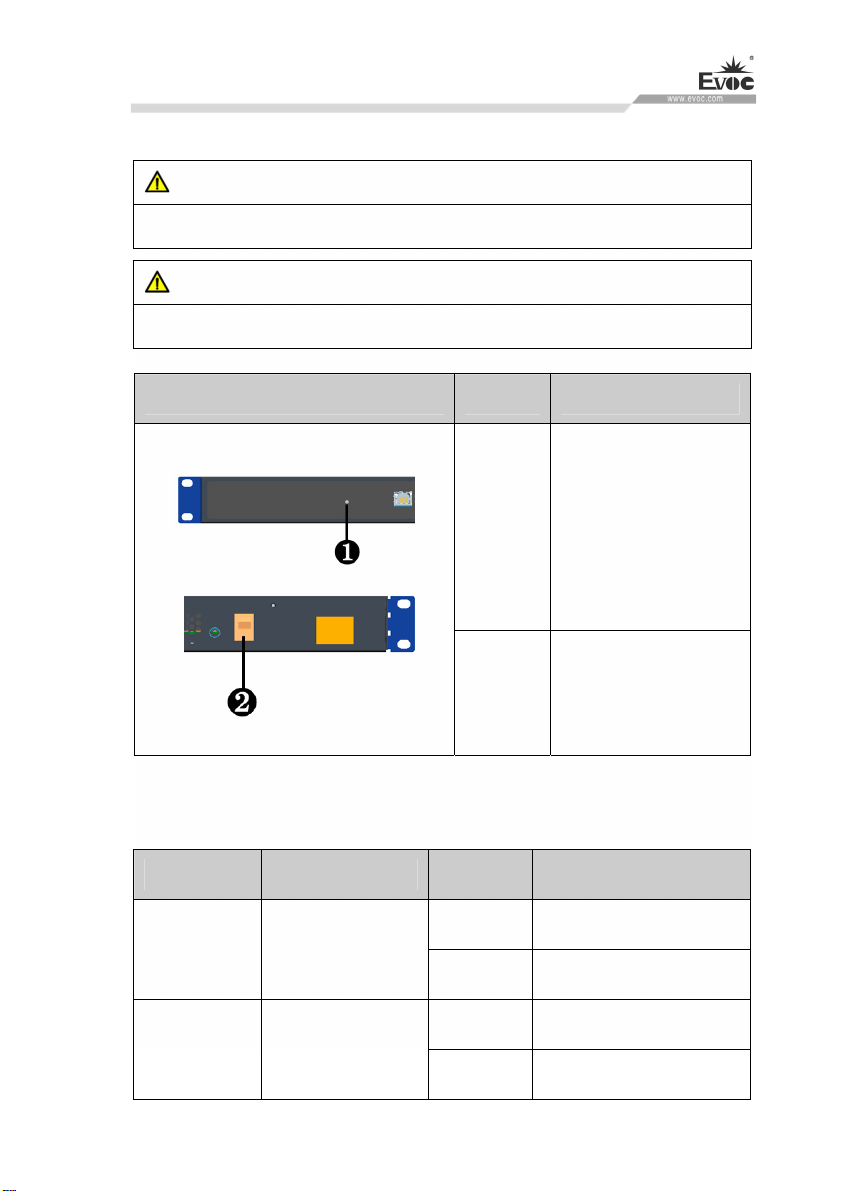
Front View of NPC-8130-02 Location Description
1 Bypass1 LED
indicator
2 Bypass2 LED
indicator
3 LAN
4 CONSOLE
5 USB
6 HDD LED
indicator
7 PWR LED
indicator
8 VGA
9 RESET switch

Product Introduction
· 6 · NPC-8130
Rear View of the PC Location Description
1 Ground screw
2 Power switch
3 Power
connector
1.3.2 Internal Layout
Internal Layout of the PC Location Description
1 Power adapter
2 Electrical port
board
3 Motherboard
4 System fan
Product Introduction
NPC-8130 · 7 ·
1.3.3 Operation Control
Warning
Pressing On/Off button won’t cut off the power of the PC!
Caution
When the PC executes hardware reset, data may be lost.
Internal Layout of the PC Location Description
1
Reset button
A pointed object or a
clip can be used to
operate the reset button.
Pressing this button will
trigger hardware reset
2 On/Off button used to
switch on/off the PC
1.4 Status LED
Display Meaning LED Description
Off Disconnected from power
POWER Displaying PC
status Green PC is operating
Off No access
HDD Displaying hard
drive status Yellow Being accessed

Application Scheme
· 8 · NPC-8130
2. Application Scheme
2.1 Transportation
Well-packaged products are suited for transportation by truck, ship, and plane. During
transportation, products should not be put in open cabin or carriage. During
transshipping, products should not be stored in open air without protection from the
atmospheric conditions. Products should not be transported together with inflammable,
explosive and corrosive substances and are not allowed to be exposed to rain, snow
and liquid substances and mechanical force.
2.2 Storage
Products should be stored in package box when it is not used. And warehouse
temperature should be 0°C ~ 40°C, and relative humidity should be 20% ~ 85%. In
the warehouse, there should be no harmful gas, inflammable, explosive products, and
corrosive chemical products, and strong mechanical vibration, shock and strong
magnetic field interference. The package box should be at least 10cm above ground,
and 50cm away from wall, thermal source, window and air inlet.
Caution!
Risk of destroying the device!
When shipping the PC in cold weather, please pay attention to the extreme
temperature variation. Under this circumstance, please make sure no water
drop (condensation) is formed on the surface or interior of the device. If
condensation is formed on the device, please wait for over twelve hours before
connecting the device.

Application Scheme
NPC-8130 · 9 ·
2.3 Opening the Box and Initial Examination
2.3.1 Opening the Box
Please pay attention to the following issues when opening the box:
●Do not discard the original packing material. Please keep the original packing
material for re-transportation.
●Please keep the documentation at a safe place. The documentation, which is a part
of the device, is required for initial device debugging.
●When doing the initial examination, please check whether there are distinct
damages to the device caused during the transport.
●Please check whether the delivery contains the intact device and all of the
independently ordered accessories. Please contact the customer service when any
unconformity or transportation damages occur.
2.3.2 Markings for PC Identification
Attention
When the product needs to be repaired or after it has been stolen, these codes can
be used to identify the PC. Please do not rip them off.
Serial number: located on the chassis body (as shown below)

Application Scheme
· 10 · NPC-8130
2.4 External Environment Conditions
The following conditions should be considered when planning the project:
The weather and mechanical environment conditions specified in the operation
manual should be observed.
Please avoid extreme environment conditions. The PC should be protected
against dust, moisture and heat.
Please avoid direct exposure to sunlight.
Please make sure that other assemblies and side of cabinet are at least 50mm
and 100mm away from the top and below the PC respectively.
Please do not block the ventilation hole of the PC.
The installation position requirement for the PC should be always observed.
The connected or installed I/O should not generate reverse voltage of more than
0.5V inside the PC.

Product Installation
NPC-8130 · 11 ·
3. Product Installation
3.1 Installation Information
Before installing the PC, please read the installation instructions below:
Attention
When carrying out installation in the switch cabinet, please observe assembly
guidelines and related DIN/VDE requirements, or specific regulations of the
country/region.
3.2 Mounting Method
■19″Rack Mount □Desktop □Embedded Panel
□Wall Mount □VESA Standard Arm □Portable
□Others___________
3.2.1 19″Rack Mount
Step: As shown in the left
picture, use screws to fasten the
PC onto the cabinet
Note: The PC must be placed on
the supporting board or guiding
rail. Do not fasten the PC only
by the screws on the front panel.

PC Connection
· 12 · NPC-8130
4. PC Connection
4.1 Things to Know before Connection
Warning
The connected or built-in peripherals with opposite polarities are not allowed.
Warning
The device only operates when connecting with grounded power. No operation is
allowed when the device power is ungrounded or only impedance is grounded.
Warning
Rated voltage of the device in use shall be in accord with power feature of the
product.
Note:
Only the peripheral devices approved for industrial application can be used. When
operating the PC, hot swappable IO modules (USB) can be used. The IO devices
without hot swap function can only be connected when the PC is powered off.
4.2 Product Grounding
Low impedance ground connection is more helpful to release the interference
produced by the external cables, the signal cables or the cables connecting the IO
module to the grounding system.

PC Connection
NPC-8130 · 13 ·
Ground Terminals
The equipotential bonding terminal ①
on the device shall be connected with
the cabinet installed with the PC or the
central grounding busbar on the device.
The minimum cross section area of the
cable shall be no less than 2.5mm2. The
maximum ground resistance should be
no more than 0.1Ω.
4.3 Connecting the Device to Power
Steps to connect the device to power
Connect the power cable to the
socket①. Before insertion, please
confirm the input voltage complies with
the power feature of this product.
Danger
Disconnect the power source and data cable during a lightning storm.
Attention
The PC is completely isolated from the power supply only by disconnecting the
power connector.
Table of contents
Other EVOC Industrial PC manuals

EVOC
EVOC LNB-1406 User manual

EVOC
EVOC PPC-1781 Series User manual

EVOC
EVOC MEC-4032 User manual

EVOC
EVOC EIS-2205 User manual

EVOC
EVOC IPC-820 User manual

EVOC
EVOC P19 Series User manual

EVOC
EVOC MEC 7003 User manual

EVOC
EVOC MEC-5031-M Series User manual

EVOC
EVOC P15 Series User manual

EVOC
EVOC PPC-1006 User manual


