EVOC MEC-4032 User manual

特种计算机
Industrial Computer
产品说明书
User Manual
MEC-4032
微型低功耗无风扇嵌入式整机
Low Power Fanless Micro Embedded PC
Version: C02

Legal Information
Warnings
Please pay attention to the tips within the manual so as to avoid personal injury or
property losses. The tips for personal injury are indicated in warning triangles while
the tips only related to property losses have no warning triangles. The warning tips are
listed as follows with the hazardous scale from severe to slight.
Danger
If handled carelessly, death or severe human injury will occur.
Warning
If handled carelessly, death or severe human injury might occur.
Caution
Warning triangle indicates that slight human injury might occur if handled carelessly.
Note
Unexpected result or status might occur, if not handled according to the tips.
Professional Personnel
The product/system covered by the manual can only be handled by qualified and
professional personnel. During operation, please follow the respective instructive
manuals, especially the safety warnings. The professional personnel have been trained
and possess relevant experiences; therefore, he/she could be aware of the risks of the
product/system and avoid possible damages.
EVOC Product
Please pay attention to the following instructions:
Warning
EVOC product can only be used according to the descriptions within the manual,
including the contents and the relevant technical documents. If the products or
components from other companies are required, please get the recommendation and
grant from EVOC first. Proper transportation, storage, assembly, installation,
debugging, operation and maintenance are prerequisite to ensure product safety and
normal operation; therefore, please ensure permitted environment conditions and pay
attention to the tips within the manual.

Copyright Notice
Information offered in this manual is believed to be correct at the time of printing, and
is subject to change without prior notice in order to improve reliability, design and
function and does not represent a commitment on the part of the manufacturer. In no
event will the manufacturer be liable for direct, indirect, special, incidental, or
consequential damages arising out of improper installation and/or use, or inability to
use the product or documentation.
This user manual is protected by copyright. No part of this manual may be reproduced,
stored in any retrieval system, or transmitted, in any form or by any means,
mechanical, electronic, photocopied, recorded or otherwise, without the prior written
permission from the manufacturer.
Trademarks
EVOC is a registered trademark of EVOC Intelligent Technology Co., Ltd. Other
product names mentioned herein are used for identification purposes only and may be
trademark and/or registered trademarks of their respective companies.
Warranty Terms:
The warranty on the product lasts for one year. If the user has additional requirements,
the contract signed between the two sides shall prevail.
Please visit our website: http://www.evoc.com for more information,
Hotline: 4008809666

About this manual
Scope of the Manual
The manual is appropriate for EVOC MEC-4032.
Convention
The term “the PC” or “the Product” within the manual usually stands for EVOC
MEC-4032.
Instructions
Safety instructions
To avoid property losses or individual injury, please pay attention to the safety
instructions within the manual. The warnings within the manual are marked with
warning triangle , whose existence is dependent upon the scale of the
potential hazard.

Contents
1. Product Introduction .................................................................................................1
1.1 Overview.........................................................................................................1
1.2 Specifications..................................................................................................1
2. Application Scheme ..................................................................................................4
2.1 Transportation .................................................................................................4
2.2 Storage ............................................................................................................4
2.3 Opening the Box and Initial Examination.......................................................5
2.4 MountingMode ..............................................................................................5
3. Device Connection....................................................................................................6
3.1 Notices before Connection..............................................................................6
3.2 Product Grounding..........................................................................................6
3.3 Connecting the Device to Power.....................................................................7
4. Instructions ...............................................................................................................8
4.1 Outer Appearance ...........................................................................................8
4.2 Product Drawing and Installation Dimensions................................................8
4.3 External Structure ...........................................................................................9
4.4 Operation Control .........................................................................................10
4.5 Indicator........................................................................................................10
4.6 Jumper Setting ..............................................................................................10
5. Assembly and Maintenance ....................................................................................14
5.1 Overall Assembly Drawing...........................................................................14
5.2 Opening the Cover ........................................................................................15
5.3 Installation and Removal of Motherboard.....................................................15
5.3.1 Installing the Motherboard.................................................................15

5.3.2 Removing the Motherboard ...............................................................16
5.4 Installation and Removal of Hard Drive .......................................................16
5.5 Installation and Removal of Power Supply...................................................17
5.5.1 Installing the Power ...........................................................................17
5.5.2 Removing the Power..........................................................................17
5.6 Installing the Mounting Bracket....................................................................18
6. Installing the Drivers ..............................................................................................19
7. Appendix.................................................................................................................20
7.1 Troubleshooting and Solutions......................................................................20
Product Introduction
MEC-4032 - 1 -
1. Product Introduction
1.1 Overview
MEC-4032 is a low power fanless micro embedded PC. The product
contains Intel® Atom™ D2550 + NM10 chipset, and supports Windows XP,
Windows 7, Linux operating systems. In addition, a pluggable installation
method makes adding or removing HDD quicker and more convenient.
Shaped by galvanized plate, the PC features simple structure, highly
reliable system and strong environmental adaptability, and provides excellent
dust-proof, heat dissipation, anti-vibration and EMC performance.
The PC can be used in a wide range of fields, such as digital health
information system, electronic medical record system, anesthesia information
management system, bus stop board and airport flight information display
control.
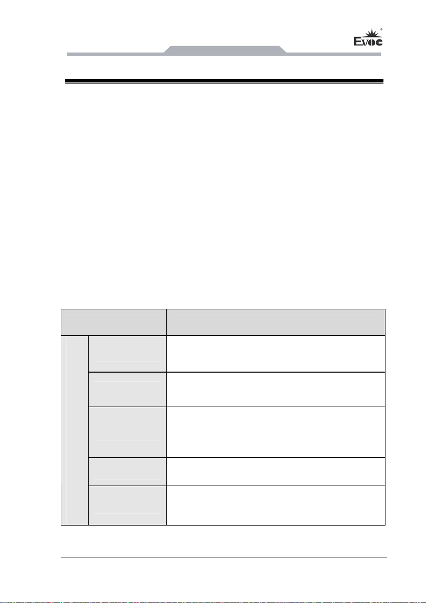
1.2 Specifications
Items Definition
Micro processor Onboard Intel® Atom™ D2550 (dual-core) processor
Chipset Intel® ATOM™ D2550 + NM10
Memory
1 x 204Pin DDR3 SO-DIMM memory slot. Supported
memory types: Un-buffered, NO-ECC. Maximum
memory capacity supported: 4GB
Display Supports VGA, DVI and HDMI displays
Main Functional Index
Network Provides two 10/100/1000Mbps LAN ports. LAN1
supports Wake-On-LAN and network boot
Product Introduction
- 2 - MEC-4032
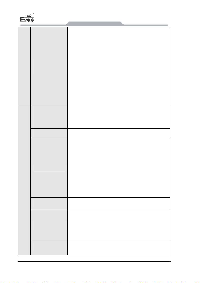
External IO
ports
1 x VGA port
1 x DVI port
1 x HDMI port
1 x standard keyboard/mouse port
One set of LINE_OUT and MIC_IN audio
connectors
2 x RJ45 LAN port
6 x standard USB2.0 port
6 x COM port; COM2, COM3, COM4, COM5,
COM6 supports RS-232/RS-422/RS-485 modes
Dimensions
(Excluding
mounting ear)
230mm(W) x 85.4mm(H) x 190mm(D)
Net weight Appr. 3.45Kg
Temperature
Operating temperature:
Band hard disk work temperature :-5℃~45℃;
Band the Cfast card or SSD work
temperature:-20℃~60℃;
(Note: CFast card has a function of anti-high
temperature, which can prevent data loss when the
card is used in a high temperature environment.)
Storage temperature: -30℃~70℃
Humidity 5%~95% (Non-condensing)
EMC
Limits of radio disturbance are compliant with
GB9254-2008, class A;
Limits of immunity are compliant with the
threshold of GB/T 17626.x
Main Functional Index
Reliability MTBF≥100000h
MTTR≤0.5h

Product Introduction
MEC-4032 - 3 -
Safety Meets basic requirements of GB4943
Mechanical and
environmental
adaptability
Anti-vibration: 5-17Hz/1.0mm amplitude;
17-200Hz/1.0g acceleration;
Anti-shock: 10g acceleration, 11ms duration
Power
12-24VDC Input /Maximum5A;
Power consumption of the PC: 13W (standby);
Power consumption of the PC: 20W (operating 3D
100%)
Note: The maximum support of the input voltage
9-32VDC, over this range, the machine will not boot.

Application Scheme
- 4 - MEC-4032
2. Application Scheme
2.1 Transportation
Well-packaged products are suited for transportation by all kinds of vehicles. During
transportation, products should not be put in open cabin or carriage. During
transshipping, products should not be stored in open air without protection from the
atmospheric conditions. Products should not be transported together with inflammable,
explosive and corrosive substances and are not allowed to be exposed to rain, snow
and liquid substances and mechanical force.
2.2 Storage
Products should be stored in package box when it is not used. And warehouse
temperature should be 0°C ~ 40°C, and relative humidity should be 20% ~ 85%. In
the warehouse, there should be no harmful gas, inflammable, explosive products, and
corrosive chemical products, and strong mechanical vibration, shock and strong
magnetic field interference. The package box should be at least 10cm above ground,
and 50cm away from wall, thermal source, window and air inlet.
Caution!
Risk of destroying the device!
When shipping the PC in cold weather, please pay attention to the extreme
temperature variation. Under this circumstance, please make sure no water
drop (condensation) is formed on the surface or interior of the device. If
condensation is formed on the device, please wait for over twelve hours before
connecting the device.

Application Scheme
MEC-4032 - 5 -
2.3 Opening the Box and Initial Examination
Opening the Box
Please pay attention to the following issues when opening the box:
●Do not discard the original packing material. Please keep the original packing
material for re-transportation.
●Please keep the documentation at a safe place. The documentation, which is a part
of the device, is required for initial device debugging.
●When doing the initial examination, please check whether there are distinct
damages to the device caused during the transport.
●Please check whether the delivery contains the intact device and all of the
independently ordered accessories. Please contact the customer service when any
unconformity or transportation damages occur.
2.4 Mounting Mode
□19″Rack Mount □Desktop □Embedded Panel
■Wall Mount □VESA Standard Arm □Portable
□Others___________
Device Connection
- 6 - MEC-4032
3. Device Connection
3.1 Notices before Connection
Warning
The connected or built-in peripherals with opposite polarities are not allowed.
Warning
The device only operates when connecting with grounded power. No operation is
allowed when the device power is ungrounded or only impedance is grounded.
Warning
Rated voltage of the device in use shall be in accord with power feature of the
product.
Note:
Only the peripheral devices approved for industrial application can be used. When
operating the PC, hot swappable IO modules (USB) can be used. The IO devices
without hot swap function can only be connected when the PC is powered off.
3.2 Product Grounding
Low impedance ground connection is more helpful to release the interference
produced by the external cables, the signal cables or the cables connecting the IO
module to the grounding system.
Ground Terminals
The equipotential bonding terminal ①
on the device shall be connected with
the cabinet installed with the PC or the
central grounding busbar on the device.
The minimum cross section area of the
cable shall be no less than 5mm2, and
the maximum ground resistance shall be
no more than 0.1Ω.

Device Connection
MEC-4032 - 7 -
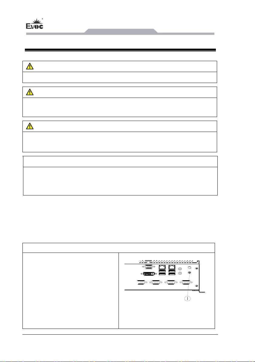
3.3 Connecting the Device to Power
Steps to connect the device to power:
Connect the power adapter with
the power input connector ①,
then press the power switch
button on the front panel of the
PC to boot up the PC, and the
power indicator will light up
green.
Danger
Disconnect the power source and data cable during a lightning storm.
Attention
The PC is completely isolated from the power supply only by disconnecting the
power connector.
Instructions
- 8 - MEC-4032
4. Instructions
4.1 OuterAppearance
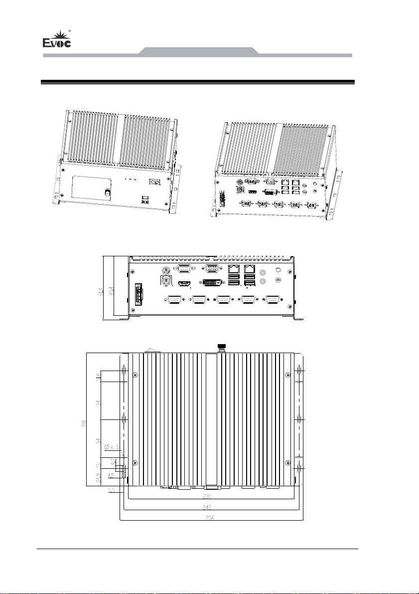
4.2 Product Drawing and Installation Dimensions
Unit: mm

Instructions
MEC-4032 - 9 -
4.3 External Structure
Front View Item Description
⑦HDD door
⑧Reset button
⑨HDD indicator
⑩Power indicator
USB5, USB6
Power on/off button
Rear View Item Description
1 KB
2 MS
3 COM1
4 VGA
5 LAN1
6 LAN2
7 LINE OUT
8 MIC
9 Ground screw
10 Power connector
11 COM2
12 HDMI
13 COM3
14 DVI
15 COM4
16 USB1/2
17 COM5
18 USB3/4
19 COM6

Instructions
- 10 - MEC-4032
4.4 Operation Control
Warning
The On/Off button signal will not disconnect PC power supply!
Caution
When the PC executes hardware reset, data may be lost.
Control Button Item Description
①
Power switch button
The On/Off button used for
bootup or shutdown.
②
Reset button
A pointed object or a clip can be
used to press reset button, and
the signal will trigger hardware
reset. Then the PC will be
rebooted (cold boot).
4.5 Indicator
Display Meaning LED Description
Off The PC is shut down or
POWER Displaying PC status
Green PC is operating
Off No access
HDD Displaying hard drive
status Yellow Data being transmitted
4.6 Jumper Setting
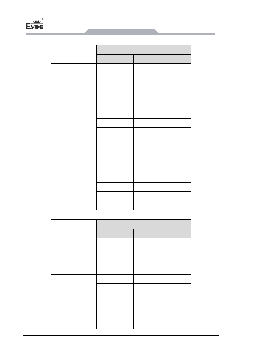
COM2~COM6 support RS-232/RS-422/RS-485 mode selection,mode selection by

Instructions
MEC-4032 - 11 -
jumper, default is RS-232。Jumper locates on the IO board, EF-COM-011MEC.
COM2、COM3 Setting:SW1\SW2\SW3\SW4\SW12\SW13\SW15\SW16
mode selection
COM2 RS-232 RS-485 RS-422
1 OFF 1 ON 1 OFF
2 OFF 2 OFF 2 ON
3 OFF 3 ON 3 ON
SW1
4 NC 4 NC 4 NC
1 ON 1 OFF 1 OFF
2 OFF 2 ON 2 ON
3 ON 3 OFF 3 OFF
SW2、SW13
4 OFF 4 ON 4 ON
1 NC 1 ON 1 OFF
2 NC 2 OFF 2 ON
3 OFF 3 ON 3 ON
SW3
4 OFF 4 ON 4 ON
mode selection
COM3 RS-232 RS-485 RS-422
1 OFF 1 ON 1 OFF
2 OFF 2 OFF 2 ON
3 OFF 3 ON 3 ON
SW4
4 NC 4 NC 4 NC
1 ON 1 OFF 1 OFF
2 OFF 2 ON 2 ON
3 ON 3 OFF 3 OFF
SW12、SW15
4 OFF 4 ON 4 ON
1 NC 1 ON 1 OFF
2 NC 2 OFF 2 ON
3 OFF 3 ON 3 ON
SW16
4 OFF 4 ON 4 ON
Instructions
- 12 - MEC-4032
COM4、COM5 Setting:SW5\SW6\SW7\SW8\SW11\SW17\SW18\SW19
mode selection
COM4 RS-232 RS-485 RS-422
1 OFF 1 ON 1 OFF
2 OFF 2 OFF 2 ON
3 NC 3 NC 3 NC
SW5
4 NC 4 NC 4 NC
1 ON 1 OFF 1 OFF
2 OFF 2 ON 2 ON
3 ON 3 OFF 3 OFF
SW6、SW8
4 OFF 4 ON 4 ON
1 NC 1 ON 1 OFF
2 NC 2 OFF 2 ON
3 OFF 3 ON 3 ON
SW7
4 OFF 4 ON 4 ON
1 OFF 1 ON 1 ON
2 NC 2 NC 2 NC
3 NC 3 NC 3 NC
SW17
4 NC 4 NC 4 NC
mode selection
COM5 RS-232 RS-485 RS-422
1 NC 1 NC 1 NC
2 NC 2 NC 2 NC
3 OFF 3 ON 3 OFF
SW5
4 OFF 4 OFF 4 ON
1 ON 1 OFF 1 OFF
2 OFF 2 ON 2 ON
3 ON 3 OFF 3 OFF
SW18、SW19
4 OFF 4 ON 4 ON
1 NC 1 ON 1 OFF
SW11
2 NC 2 OFF 2 ON
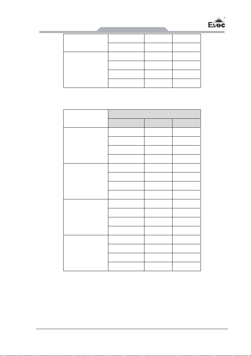
Instructions
MEC-4032 - 13 -
3 OFF 3 ON 3 ON
4 OFF 4 ON 4 ON
1 NC 1 NC 1 NC
2 OFF 2 ON 2 ON
3 NC 3 NC 3 NC
SW17
4 NC 4 NC 4 NC
COM6 Setting:SW4\SW9\SW10\SW14\SW17
mode selection
COM6 RS-232 RS-485 RS-422
1 OFF 1 ON 1 OFF
2 OFF 2 OFF 2 ON
3 NC 3 ON 3 OFF
SW9
4 NC 4 OFF 4 ON
1 ON 1 OFF 1 OFF
2 OFF 2 ON 2 ON
3 ON 3 OFF 3 OFF
SW10、SW14
4 OFF 4 ON 4 ON
1 NC 1 NC 1 NC
2 NC 2 NC 2 NC
3 OFF 3 ON 3 ON
SW17
4 OFF 4 ON 4 ON
1 NC 1 NC 1 NC
2 NC 2 NC 2 NC
3 NC 3 NC 3 NC
SW4
4 OFF 4 ON 4 ON

Assembly and Maintenance
- 14 - MEC-4032
5. Assembly and Maintenance
5.1 OverallAssembly Drawing
Item Description Item Description Item Description
1 Top cover 2 Power supply 3 Heat sink
4 Motherboard 5 Chassis 6 Indicator panel
7 Front panel 8 HDD door 9 HDD module
10 Bottom cover 11 Support bracket 12 IO plate
13 Rear panel
Table of contents
Other EVOC Industrial PC manuals

EVOC
EVOC EIS-2205 User manual

EVOC
EVOC P12 Series User manual

EVOC
EVOC PPC-1006 User manual

EVOC
EVOC MEC-5031-M Series User manual

EVOC
EVOC P19 Series User manual

EVOC
EVOC ERC-1004A User manual

EVOC
EVOC PPC-1781 Series User manual

EVOC
EVOC LNB-1406 User manual

EVOC
EVOC NPC-8130 User manual

EVOC
EVOC ERC-1004A User manual


