Hardware Reference Manual Table of List of Figures
GFK-3014F Feb 2023
List of Figures vii
List of Figures
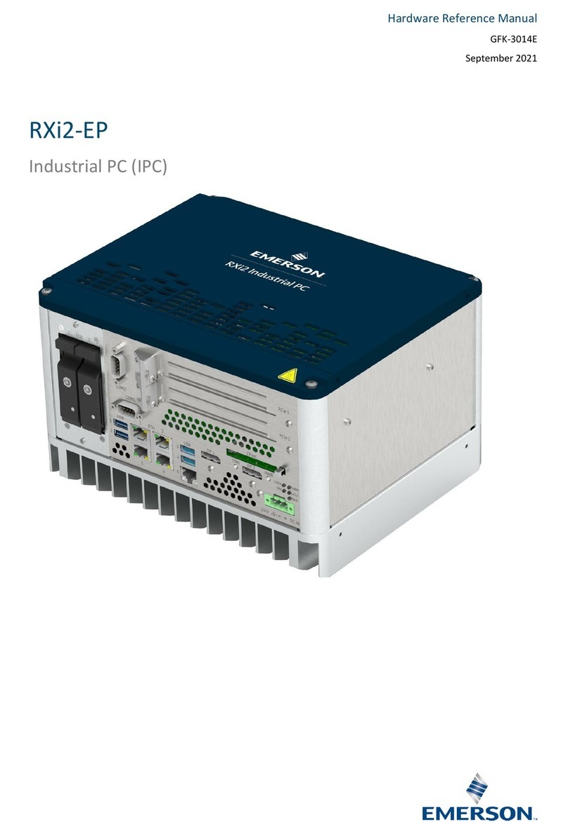
Figure 1-1 0-slot RXi2-EP IPC....................................................................................................................2
Figure 1-2 1-slot RXi2-EP IPC....................................................................................................................2
Figure 1-3 2-slot RAID RXi2-EP IPC ..........................................................................................................3
Figure 1-4 4-slot RXi2-EP IPC....................................................................................................................3
Figure 1-5 4-slot RAID RXi2-EP IPC ..........................................................................................................4
Figure 1-6 2–slot RXi2-EP IPC System Block Diagram ..........................................................................6
Figure 2-1 RXi2-EP IPC Packaging ........................................................................................................ 10
Figure 3-1 Heat Dissipation Clearance ................................................................................................ 12
Figure 3-2 Flat Wall Mounting with Mounting Plates........................................................................ 13
Figure 3-3 Flat Wall Mounting Through Wall...................................................................................... 14
Figure 4-1 RXi2-EP Top Cover................................................................................................................ 18
Figure 4-2 PCIe Support Bracket Screws............................................................................................. 19
Figure 4-3 Removed PCIe Support Bracket and Screws ................................................................... 19
Figure 4-4 Removed PCIe Slot Cover ................................................................................................... 20
Figure 4-5 PCIe Board Bracket Inserted into Slot .............................................................................. 20
Figure 4-6 PCIe Board Bracket Inserted into PCIe Connector ......................................................... 21
Figure 4-7 Reattached PCIe Support Bracket ..................................................................................... 21
Figure 4-8 Reattached PCIe Bracket Screws ....................................................................................... 22
Figure 4-9 Card Holder Adjustment..................................................................................................... 22
Figure 4-10 Reattached Top Cover......................................................................................................... 23
Figure 4-11 Short Position for mPCIe Bracket...................................................................................... 24
Figure 4-12 Long Position for mPCIe Bracket....................................................................................... 24
Figure 4-13 mPCIe Board Inserted......................................................................................................... 25
Figure 4-14 mPCIe Board Mounted to RXi2-EP IPC.............................................................................. 25
Figure 4-15 SIM Interface Connected to mPCIe –Unlocked but Closed .......................................... 26
Figure 4-16 SIM Card Holder Open........................................................................................................ 26
Figure 4-17 Inserted SIM card................................................................................................................. 27
Figure 4-18 SIM Card Holder Closed and Locked................................................................................. 27
Figure 4-19 RXi2-EP IPC Connector Slot................................................................................................. 28
Figure 4-20 M.2 A-Key Insertion into Connector Slot .......................................................................... 28
Figure 4-21 M.2 A-Key Mounted to RXi2-EP IPC ................................................................................... 29
Figure 4-22 RXi2-EP IPC Connector Slot................................................................................................. 30
Figure 4-23 M.2 M-Key Insertion into Connector Slot......................................................................... 30
Figure 4-24 M.2 M-Key Mounted to RXi2-EP IPC .................................................................................. 31
Figure 4-25 RTC Battery (Removed Top Cover) .................................................................................... 32
Figure 5-1 RXi2-EP IPC Hardware Interface Overview....................................................................... 34
Figure 5-2 RXi2-EP IPC Hardware Interface Overview (2-slot Option) ............................................ 35
Figure 5-3 Status LEDs ........................................................................................................................... 35
Figure 5-4 Power Button........................................................................................................................ 36
Figure 5-5 Ethernet Interface Ports (1–slot Option) .......................................................................... 37
Figure 5-6 RJ-45 Pinout................................................................................................................................... 37
Figure 5-7 RXi2-EP IPC GBE ................................................................................................................... 38
Figure 5-8 DisplayPort Interface Ports (2–slot Option) ..................................................................... 39


