Exsys EX-41051 User manual

65
EXEXEX-
-
-410514105141051
EnglishEnglishEnglish
EXEXEX-
-
-410514105141051
EnglishEnglishEnglish
CHECK THE INSTALLED DRIVER
Click at Start<>Run< then enter “compmgmt.msc“ and click at >OK<. In the windows that
open select >Device Manager<. Under ”Ports (COM and LPT)“ you should find one or more
new ”PCI Ports“ as sample (Com3). If you see this or similar entries the card is installed
correctly.
CHANGE PORT NUMBER
If you like to change the port number for example COM3 to COM5, open the >Device Manager<
click at >COM3<, >Settings< and then >Advance<. There you can change between COM3 till
COM256.
MS-DOS
Copy the DOS driver file from the CD (D:\IO\NETMOS\98XX\DOS\NmDosln.exe) to the root
directory on your hard disk (C:\). Modify the “AUTOEXEC.BAT“ with the following line:
C:\NmDosln -a -r
After you reboot DOS , you can see the EX-41052 with COM3 and COM4. The IRQ its set from
System-BIOS and can’t be changed.
LINUX
There are no drivers available for Linux, but the card is supported by the most versions of
Linux. Because each individual distribution and kernel version of Linux is different, sadly we
cant provide a installation instruction. Please refer to the installation manual for standard I/O
ports from your Linux version! In some newer versions the card will even be installed automati-
cally after starting Linux.
1
JUMPER EINSTELLUNG & ANSCHLÜSSE:
Die EX-41051 ist eine 32-Bit PCI Seriell RS-232 Karte mit einem seriellen FIFO
16C550 Port, für den Anschluss von High-Speed seriellen RS-232 Peripherie Geräten
(z.B. Modem, Plotter usw.). Sie unterstützt den 32 und 64-Bit PCI bzw. PCI-X Bus mit 5
Volt und 3,3 Volt. Es ist nicht möglich die I/O Adressen und Interrupts manuell einzu-
stellen, da die Einstellungen der Karte vom System (BIOS) und beim Installieren des
Betriebssystems automatisch vorgenommen werden. Es besteht bei Bedarf die Mög-
lichkeit, +5V- oder +12V auf einen von vier Pins zu legen (POS System).
BESCHREIBUNG & TECHNISCHE DATEN :
AUFBAU :
Kompatibilität: PCI oder PCI-X, 33Mhz
Betriebs Systeme:
DOS/ ME/ 2000/ XP/ Vista/ 7/ 8/ Server20xx/ (Linux vom OS)
Anschlüsse: 1 x 9 Pin Seriell D-SUB Stecker
Lieferumfang: EX-41051, Treiber CD, Deutsche Anleitung
Zertifikate:
CE
CECE
CE
/ FCC / RoHS / WEEE DE97424562 / WHQL
DRIVER INSTALLATION :
Mit der EX-41051 haben Sie die Möglichkeit +5V- oder +12V auf einen der folgenden vier Pins,
des Steckers S1 zu konfigurieren :
Achtung! Nur konfigurieren wenn für das Peripheriegerät auch +5Volt oder +12Volt gebraucht
wird. Für normale Anwendung Jumper nicht verändern sonst werden ihre Geräte beschädigt!
JP2: JP2 gesetzt auf PCI = +5 oder +12V kommt vom PCI BUS
JP2 gesetzt auf AUX = +5 oder +12V kommt vom PC Netzteil
JP3:
(S1)
+5V
+12V
Dis
Pin 4
Pin 9Pin 8Pin 1
Achtung!! Es darf pro Pin immer nur eine Spannung einge-
stellt werden!
+5V: +5V auf den jeweiligen Pin des Anschlusses
+12V: +12V auf den jeweiligen Pin des Anschlusses
DIS: Kein Strom auf den Anschlüssen (Standard)
PCI AUX
+5V
+12V
DB9M:
Pin Signal Pin Signal Pin Signal
1 CDC 4 DTR 7 RTS
2 RXD 5 GROUND 8 CTS
3 TXD 6 DSR 9 RI
Serial 9 Pin D-SUB male connector :
If you are ready with the jumper settings, please proceed with the following installation
instructions. Because the designs of computers are different, only general installation
instructions are given. Please refer your computer’s reference manual whenever in doubt.
1. Turnoff the power to your computer and any other connected peripherals.
2. Remove the mounting screws located at the rear and/or sides panels ofyour Comput-
er and gently slide the cover off.
3. Locate an available expansion slot and remove its covers from the rear panel of your
computer. Make sure it is the right expansion slot for the card (see card description)
4. Align the card with the expansion slot, and then gently but firmly, insert the card.
Make sure the card is seated and oriented correctly. Never insert the card by force!
5. Then connect the cardwith a screw to the rear panel of the computer case.
6. Gently replace your computer’s cover and the mounting screws.
HARDWARE INSTALLATION :
DRIVER INSTALLATION :
Windows ME/ 2000/ XP/ Vista/ 7/ 8
After starting Windows it recognizes a new “PCI Controller“ and open the hardware assistant.
Please choose manual installation and put the driver CD into your CD-Rom drive. Now enter
the Path "D:\IO\NETMOS\98XX" and then the directory of your operating system “WINME“
“WIN2000“ “WINXP“ “WINXP_64“ “Vista32“ “Vista64“ “WIN7_8_32“ or “WIN7_8_64“ into
the box for the Path/Source and click at >next/continue<. Now Windows search for the drivers
in the specified directory. Follow the hardware assistant and finish the installation. If Windows
recognizes other new devices repeat the above described steps. Attention! Restart your PC in
any case after installing the drivers.
CHECK THE INSTALLED DRIVER
Click at Start<>Run< then enter “compmgmt.msc“ and click at >OK<. In the windows that
open select >Device Manager<. Under ”Ports (COM and LPT)“ you should find one or more
new ”PCI Ports“ as sample (Com3). If you see this or similar entries the card is installed
correctly.
CHANGE PORT NUMBER
If you like to change the port number for example COM3 to COM5, open the >Device Manager<
click at >COM3<, >Settings< and then >Advance<. There you can change between COM3 till
COM256.
Windows Server 20xx
After starting Windows it recognizes a new “PCI Controller“ and open the hardware assistant.
Please choose manual installation and put the driver CD into your CD-Rom drive. Now enter
the Path "D:\IO\NETMOS\98XX" and then the directory of your operating system for Server
2000: “WIN2000“ for Server 2003: “WINXP“ or “WINXP_64“ for Server 2008: “Vista32“ or
“Vista64“ and for Server 2008R2 and Server 2012: “WIN7_8_32“ or “WIN7_8_64“ into the
box for the Path/Source and click at >next/continue<. Now Windows search for the drivers in
the specified directory. Follow the hardware assistant and finish the installation. If Windows
recognizes other new devices repeat the above described steps. Attention! Restart your PC in
any case after installing the drivers.
JUMPER SETTING & CONNECTORS:
BedienungsanleitungBedienungsanleitung
Vers. 1.3 / 03.05.12
J2:
1 +5V
2 GND
3 GND
4 +12V
Wenn JP2 auf AUX gestellt ist muss J2 mit dem Stroman-
schluss vom PC Netzteil verbunden werden!
Bitte auf die richtige Polarität achten!
Achtung! Stecker nie bei eingeschaltetem PC ein oder
ausstecken!
S1
9 Pin Buchse
Seriell Anschluss
Seriell Chip 16C550
mit 16-Byte Buffer
und PCI-Bridge
Anschluss vom
Netzteil für +5V oder
+12V Spannung
+5V oder +12V
einstellbar auf den
9 Pin Stecker

2 3 4
EXEXEX-
-
-410514105141051
DeutschDeutschDeutsch
EXEXEX-
-
-410514105141051
DeutschDeutschDeutsch
The EX-41051 is a plug & play 32-Bit high-speed serial RS-232 expansion card for the
PCI-bus. The EX-41051 provides one 9 pin high speed RS-232 serial port. The EX-
41051 design utilizes the 16C550 UART which incorporates the latest in high speed
interface technology. It supports motherboards with 32- and 64-Bit Bus and 5- and
3.3Volt PCI-bus power. It is not possible to change the address or IRQ settings manual-
ly because they will be obtained automatically by the system BIOS and operating sys-
tem. If you need you can set +5V or +12V to four different pins from the two connectors
(POS System).
DESCRIPTION & TECHNICAL INFORMATION :
Compatibility: PCI or PCI-X, 33Mhz
Operating system:
DOS/ ME/ 2000/ XP/ Vista/ 7/ 8/ Server20xx/ (Linux by OS)
Connections: 1 x 9 pin D-SUB serial male connector
Extent of delivery: EX-41051, Driver CD, English manual
Certificates:
CE
CECE
CE
/ FCC / RoHS / WEEE DE97424562 / WHQL
ÜBERPRÜFEN DER INSTALLIERTEN TREIBER
Klicken Sie auf Start<>Ausführen< geben Sie “compmgmt.msc“ ein und klicken Sie auf
>OK<. Wählen Sie nun >GeräteManager<. Dort müssten Sie unter „Anschlüsse (COM und
LPT)“ einen neuen „PCI Port“ z.B. (Com3) sehen. Wenn Sie diese oder ähnliche Einträge
sehen, ist die Karte korrekt installiert.
ÄNDERN DER PORT NUMMER
Hier können Sie die Ports ändern, klicken Sie z.B. auf >COM3< >Anschlusseinstellung< und
>Erweitert<. Sie können dann zwischen COM3 und COM256 wählen!
MS-DOS
Kopieren Sie das File von der CD (z.B. D:\IO\NETMOS\98XX\DOS\NmDosln.exe) auf Ihre
Festplatte. Ergänzen Sie die „AUTOEXEC.BAT“ mit folgender Zeile:
NmDosln -a -r
Beim hochfahren des Betriebssystem DOS wird nun die EX-41052 als COM3 und COM4 eingetra-
gen. Der IRQ wird vom System/BIOS vergeben und kann nicht verändert werden.
LINUX
Es gibt für diese Karte keine Linux Treiber, sie wird allerdings unter den meisten Linux Versio-
nen unterstützt. Da sich die einzelnen Distributionen und Kernelversionen sehr voneinander
unterscheiden, können wir Ihnen leider keine Installationsanweisung geben. Bitte halten Sie
sich an die Installationsanweisung für Standard I/O Ports Ihrer Linux Version. In einigen Versi-
onen wird die Karte automatisch beim Start installiert.
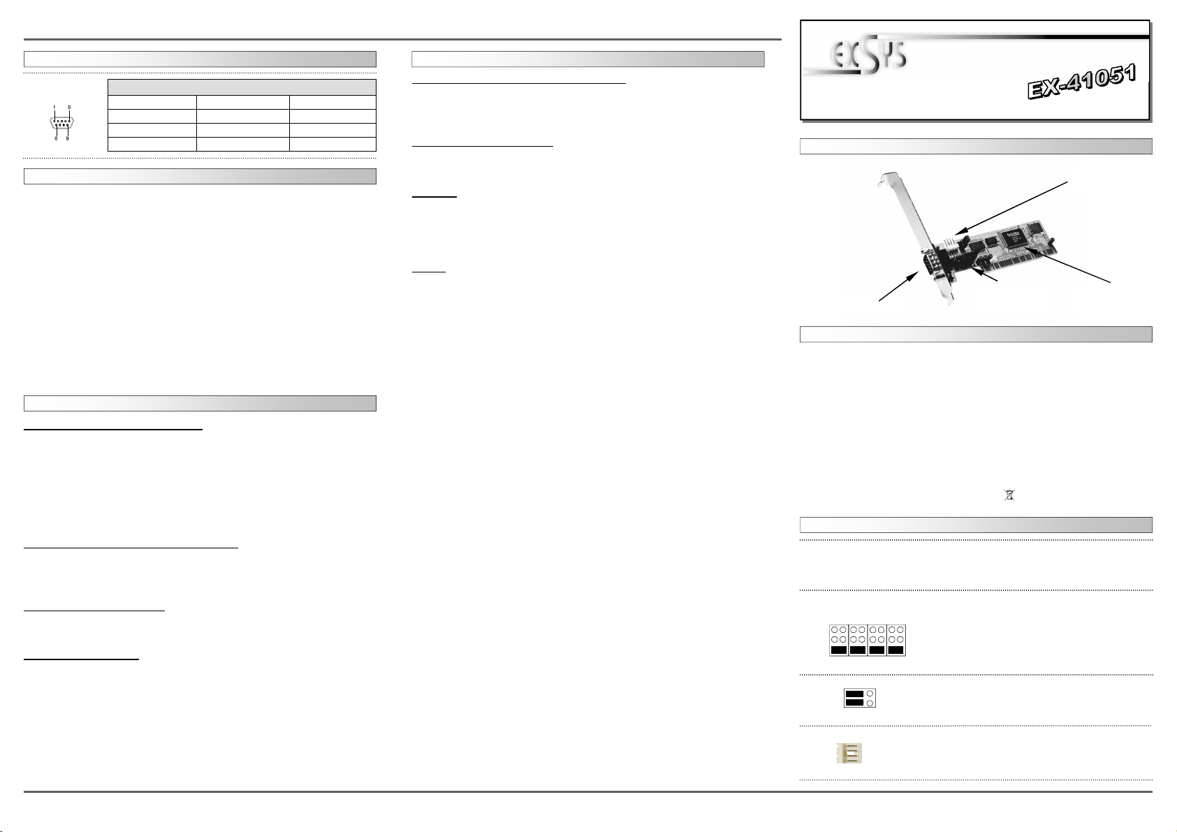
LAYOUT :
JUMPER SETTING & CONNECTORS:
TREIBER INSTALLATION :
On the EX-41051 you can configure +5V or +12V to four different pins from the 9 pin male
connector :
Attention !! Only change if you really need +5Volt or +12Volt for the peripheral device. For
normal use, don‘t change the jumper or your hardware can be damaged.
DB9M:
Pin Signal Pin Signal Pin Signal
1 CDC 4 DTR 7 RTS
2 RXD 5 GROUND 8 CTS
3 TXD 6 DSR 9 RI
Seriell 9 Pin D-SUB Stecker :
JUMPER EINSTELLUNG & ANSCHLÜSSE:
HARDWARE INSTALLATION :
Wenn Sie die Karte installieren, beachten Sie bitte die folgenden Hinweise. Da es grosse
Unterschiede bei Computern gibt, können wir Ihnen nur eine generelle Anleitung zum
Einbau geben. Bei Unklarheiten halten Sie sich bitte an die Bedienungsanleitung Ihres
Computersystems.
1. Schalten Sie Ihren Rechner und alle angeschlossenen Peripheriegeräte aus und
ziehen Sie bei allen Geräten den Netzstecker.
2. Lösen Sie die Schrauben des Gehäuses auf der Rückseite Ihres Computers und
entfernen Sie vorsichtig das Gehäuse.
3. Suchen Sie einen freien Steckplatz und entfernen sie das Slotblech, stecken Sie die
Karte vorsichtig in den ausgewählten Steckplatz ein. Stellen sie sicher das es sich um
denrichtigen Steckplatz handelt! (siehe Kompatibilität unter technische Daten)
4. Beachten Sie, das die Karte korrekt eingesteckt wird und das kein Kurzschluss ent-
steht. Wenden sie keine Gewalt an um die Karte einzustecken!
5. Danach befestigen Sie die Karte bitte mit einer Schraube am Gehäuse.
6. Jetzt können das Computergehäuse mit den Schrauben wieder schliessen.
TREIBER INSTALLATION :
Windows ME/ 2000/ XP/ Vista/ 7/ 8
Windows erkennt beim Start einen neuen “PCI Controller“ und öffnet automatisch den
Windows Hardwareassistenten. Wählen Sie die manuelle Installation aus und legen Sie die
Treiber CD in Ihr CD-ROM Laufwerk (z.B. Laufwerk D:). Geben Sie nun den Pfad
"D:\IO\NETMOS\98XX" und dann das Verzeichnis Ihres Betriebssystems “WINME“
“WIN2000“ “WINXP“ “WINXP_64“ “Vista32“ “Vista64“ “WIN7_8_32“ oder “WIN7_8_64“ in
das jeweilige Feld für die Quelle/Pfad ein und klicken Sie auf >weiter<. Windows sucht nun
nach den Treibern in dem angegebenen Verzeichnis. Folgen Sie den Anweisungen des Hard-
wareassistenten und beenden Sie die Installation. Sollte Windows noch weitere neue Hard-
ware erkennen, wiederholen Sie die oben angegebenen Schritte. Wichtig! Starten Sie Ihren
PC in jedem Fall nach der Installation neu.
ÜBERPRÜFEN DER INSTALLIERTEN TREIBER
Klicken Sie auf Start<>Ausführen< geben Sie “compmgmt.msc“ ein und klicken Sie auf
>OK<. Wählen Sie nun >GeräteManager<. Dort müssten Sie unter „Anschlüsse (COM und
LPT)“ einen neuen „PCI Port“ z.B. (Com3) sehen. Wenn Sie diese oder ähnliche Einträge
sehen, ist die Karte korrekt installiert.
ÄNDERN DER PORT NUMMER
Hier können Sie die Ports ändern, klicken Sie z.B. auf >COM3< >Anschlusseinstellung< und
>Erweitert<. Sie können dann zwischen COM3 und COM256 wählen!
Windows Server 20xx
Windows erkennt beim Start einen neuen “PCI Controller“ und öffnet automatisch den
Windows Hardwareassistenten. Wählen Sie die manuelle Installation aus und legen Sie die
Treiber CD in Ihr CD-ROM Laufwerk (z.B. Laufwerk D:). Geben Sie nun den Pfad
"D:\IO\NETMOS\98XX" und dann das Verzeichnis Ihres Betriebssystems für Server 2000:
“WIN2000“ für Server 2003: “WINXP“ oder “WINXP_64“ für Server 2008: “Vista32“ oder
“Vista64“ und für Server 2008R2 und Server 2012: “WIN7_8_32“ oder “WIN7_8_64“ in das
jeweilige Feld für die Quelle/Pfad ein und klicken Sie auf >weiter<. Windows sucht nun nach
den Treibern in dem angegebenen Verzeichnis. Folgen Sie den Anweisungen des Hard-
wareassistenten und beenden Sie die Installation. Sollte Windows noch weitere neue Hard-
ware erkennen wiederholen Sie die oben angegebenen Schritte. Wichtig! Starten Sie Ihren
PC in jedem Fall nach der Installation neu.
JP2: JP2 set to PCI = +5 or +12V from PCI BUS
JP2 set to AUX = +5 or +12V from PC power supply
JP3:
(S1)
+5V
+12V
Dis
Pin 4
Pin 9Pin 8Pin 1
Attention!! You can only choose one voltage at a time!
+5V: +5V to the selected pin
+12V: +12V to the selected pin
DIS: No power to any pin (default)
PCI AUX
+5V
+12V
User ManualUser Manual
Vers. 1.3 / 03.05.12
J2: If JP2 is set to AUX the J2 must be connected with pc
power supply! Please make sure you connect the plug in
the right direction. Never connect or release the plug
while the PC power is on!
S1
9 Pin male
Serial connector
Serial Chip 16C550
with 16-Byte buffer
and PCI-Bridge
Connector for the
Power Supply
(+5V or +12V)
+5V or +12V setting
to the 9 Pin male
connector
1 +5V
2 GND
3 GND
4 +12V
Other Exsys PCI Card manuals

Exsys
Exsys EX-11494-3 User manual

Exsys
Exsys EX-1072 User manual

Exsys
Exsys EX-1062 User manual

Exsys
Exsys EX-11042 User manual

Exsys
Exsys EX-6072PoE User manual

Exsys
Exsys EX-6072-4K User manual

Exsys
Exsys EX-41021 User manual

Exsys
Exsys EX-60112 User manual

Exsys
Exsys EX-41062 User manual

Exsys
Exsys EX-41016-2WO User manual

Exsys
Exsys EX-41054 User manual

Exsys
Exsys EX-44140-2 User manual

Exsys
Exsys EX-60102 User manual

Exsys
Exsys EX-45034 User manual

Exsys
Exsys EX-11087 User manual

Exsys
Exsys EX-41384 User manual

Exsys
Exsys EX-1062 User manual

Exsys
Exsys EX-6072-4K User manual

Exsys
Exsys EX-3516 Reference manual

Exsys
Exsys EX-1093 User manual