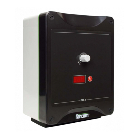
Fancom VLR.6 User manual

VLR.6
MANUAL
GB
US
CA

Fancom VLR.6
Copyright
All rights reserved. Reproduction of any part of this manual in any form
whatsoever without Fancom’s express written permission is forbidden. The
contents of this manual are subject to change without notice. All efforts have
been made to assure the accuracy of the contents of this manual. However,
should any errors be detected, Fancom would greatly appreciate being informed
of them. The above notwithstanding, Fancom can assume no responsibility for
any errors in this manual or their consequence.
Copyright 2001 Fancom B.V.
Panningen, the Netherlands
GB011101 ALL RIGHTS RESERVED
Art.Nr. A5911106
Always keep this manual by the end station
Always keep this manual by the end stationAlways keep this manual by the end station
Always keep this manual by the end station

Fancom VLR.6
EC-Declaration of compliance
EC Declaration of compliance
Manufacturer : Fancom B.V.
Address : Industrieterrein 34
City : Panningen (the Netherlands)
hereby declares that the: VLR.6
satisfies the following standards or other standard document(s):
Emission characteristics were assessed according to standard NEN-EN
50081-1. The susceptibility was established in accordance with the
requirements of the generic immunity standard NEN-EN 50082-1 and
the surge immunity standard NEN-EN-IEC 61000-4-5 4kV common
mode and 2kV differential mode. The low voltage guide according to
NEN-EN-IEC 60950.
Satisfies the conditions set out in:
1. The Low Voltage Guideline (Directive 73/23/EEG, as last amended
by the Directive 93/68/EEG).
2. The EMC Guideline (Directive 89/336/EEG, as last amended by the
Directives 92/31/EEG and 93/68/EEG).
Place: Panningen Date: 1-11-2001
(Signature) (Signature)
(Name of the signatory 1)
Math Stammen
(Name of the signatory 2)
Jo Reinders
(Occupation of the signatory 1)
Research manager
(Occupation of the signatory 2)
Project Manager climate systems

Fancom VLR.6
Table of contents
Table of contents
About this manual
1. Introduction ............................................................................................1
2. Technical specifications .........................................................................2
3. Mounting and installation .....................................................................3
4. Operation ................................................................................................4
5. Points of attention ..................................................................................5
5.1 Analog control .................................................................................5
5.2 Jumper setting................................................................................6
6. Adjustment procedures ..........................................................................7
6.1 Fan without DSR-feedback ............................................................7
6.2 Fan with DSR-feedback .................................................................8
6.3 Lighting...........................................................................................8
6.4 Heating............................................................................................9
APPENDICES: Connection diagrams

Fancom VLR.6
About this manual
About this manual
This manual contains information about the installation and service of
an end station. Read this manual carefully and follow all safety
instructions.
If you have any questions, please do not hesitate to contact your Fancom
dealer. The subjects discussed in this manual are listed in the table of
contents.
The following symbols are used in this manual:
!Suggestions, advice and notes with additional information.
Caution
The product could be damaged, if the procedures are not followed
carefully.
Caution
Life threatening situation, if the procedures are not followed
carefully.

Fancom VLR.6
1. Introduction
1
1. Introduction
This manual describes the mounting, installation, operation and
connection of the VLR.6.
The VLR.6 is a power controller for the control of:
•1-phase voltage controllable (triac) fans
•Electronically controllable lighting (incandescent lighting and
controllable fluorescent lighting)
•Heating lamps (phase angle control)
•Heating elements (period control)
The VLR.6 has extensive manual operation possibilities in the event of
malfunctioning.

Fancom VLR.6
2. Technical specifications
2
2. Technical specifications
Power supply
Mains voltage 230Vac (-10% +6%)
or 115Vac (-10% +6%)
by power supply selection
Mains frequency 50-60Hz
Power consumption ( of VLR.6) 3.5VA
Max. current output 6A
Fuse (dimensions 6.3×32mm) Very Fast Acting 10A - 250V
Power outage relay
Relay de-energizes if the power fails 30Vac/60Vdc - max. 2A
Control
Type 10-0Vdc/0-10Vdc
Input resistance 120kΩ
Manual operation
Knob for 0-100% if the 10-0Vdc control fails
Switch for “man-0-aut” (man = directly on mains)
Housing
Plastic housing with screw on lid IP54
Dimensions (l×w×h) 180×240×140 (7.1×9.4×5.5 inches)
Weight (unpacked) 1.9kg(4.2lbs)
Ambient climate
Operating temperature range 0°C to +40°C (32°F to104°F)
Storage temperature range -10°C to 50°C (14°F to 112°F)
Relative humidity < 95%, uncondensed
!Fancom advises 2-wire connection of Fancom fans. If the fans are
connected parallel, heat production per fan may increase (causing
a shortened working life). Fancom therefore advises not to parallel
switch more than three fans. See connection diagrams.

Fancom VLR.6
3. Mounting and installation
3
3. Mounting and installation
When mounting/installing an end station, the following should be
observed:
Disconnect power before installation.
1. Use correct wires as shown on the connection diagrams and follow
all instructions.
2. Never mount the end station in a place where the weather has
direct influence (not in the sun, not in places where the temperature
can rise sharply etc.).
3. Never mount the end station in a room where animals are present
because of the (manual) control.
4. Mount the end station at such a height that the manual control can
be used.
5. Mount the end station on a flat surface; ensure that the gland nuts
are at the bottom of the computer.
6. Seal all gland nuts after connection of the end station to prevent
entry of dust, aggressive gases and/or humidity.
!Always observe the regulations of the electricity company.

Fancom VLR.6
4. Operation
4
4. Operation
In the event of malfunctioning the VLR.6 can be set manually using the
switch and knob on the front. Table 1 indicates the function of the
output at the different switch and/or knob settings.
Switch Knob
- man.
- 0
- aut.
man.
aut.
Table 1: Operation
Switch Knob Output
aut. aut. controlled voltage
aut. man. voltage adjustable
using knob
man. man./ aut. mains voltage
0 man./ aut. no activity

Fancom VLR.6
5. Points of attention
5
5. Points of attention
5.1 Analog control
The VLR.6 is set as standard as an 10-0Vdc analog control. When this
control changes into a 0-10Vdc control, jumper J3 should be changed;
see jumper setting. The manual operation connection should also be
changed. This means that the red (RD) and blue (BL) wire should be
changed around.
Fancom advises the following controls with applications, see Table 2.
Table 2: Analog control advice
Application Analog control
Fan(s) 10-0Vdc
Lighting 10-0Vdc
Heating 0-10Vdc

Fancom VLR.6
5. Points of attention
6
5.2 Jumper setting
The VLR.6 has four jumpers with which different settings can be made.
Table 3 shows the applications and corresponding jumper settings.
The factory setting is for fan(s) with DSR feedback.
Disconnect the power for the VLR.6 before setting the jumper(s).
Table 3: Jumper table
Jumper setting
Application J1 J2 J3 J4
Fan without
DSR feedback
Place with small fan
Ø35 and Ø 40.
(Jumper is in small bag
in lid)
preferably
10-0Vdc
V
Fan with DSR
feedback* Do not place preferably
10-0Vdc
V
Lighting
(incandescent /
controllable
fluorescent
Do not place preferably
10-0Vdc L
Heating
(period control) Do not place preferably**
0-10Vdc
V
* Factory setting
** Change over the red (RD) and blue (BL) wire on the manual operation connector.

Fancom VLR.6
6. Adjustment procedures
7
6. Adjustment procedures
6.1 Fan without DSR-feedback
1. Switch off the power supply to the end station.
2. Control the jumper positions.
3. Switch on the power supply.
4. Set switch and knob to AUT.
5. Turn potentiometer P1 on the VLR-board completely counter-
clockwise.
6. Turn potentiometer P2 on the VLR-board completely clockwise.
7. Set the knob on the front to MAN. and turn until the fan starts
running.
8. Using potentiometer P2 adjust the minimum voltage between "U"
and "V" so that the fan is barely running. A Fancom fan is normally
2-wire connected and the voltage between "U" and "V" not set below
60Vac. (With a 3-wire connection , do not set the Fancom fan below
45Vac).
9. Turn the knob on the front to a minimum position (not to AUT.),
until the fan stops running.
10. Using potentiometer P1 adjust the minimum voltage between "U"
and "V" (for a Fancom fan, not below 55Vac).
!If the fan is to stop running at 0% control, do not carry out steps 9
and 10. The fan may only stop running completely with a 2-wire
connection

Fancom VLR.6
6. Adjustment procedures
8
6.2 Fan with DSR-feedback
1. Switch off the power supply to the end station.
2. Control the jumper positions.
3. Switch on the power supply.
4. Set the switch and knob to AUT.
5. Turn potentiometer P1 on the VLR-board completely counter-
clockwise (and leave it in this position).
6. Turn potentiometer P2 on the VLR-board completely clockwise.
7. Set the knob to MAN. and turn until the fan starts running.
8. Using potentiometer P2 adjust the minimum voltage between "U"
and "V" (for a Fancom fan, not below 30Vac).
6.3 Lighting
1. Switch off the power supply to the end station.
2. Control the jumper positions.
3. Switch on the power supply.
4. Set the switch and knob to AUT.
5. Turn potentiometer P1 on the VLR-board completely counter-
clockwise.
6. Turn potentiometer P2 on the VLR-board completely clockwise.
7. Set the knob to MAN. and turn until the lighting is barely on.
8. Using potentiometer P2 adjust the minimum voltage between "U"
and "V" (You determine the minimum lighting position).

Fancom VLR.6
6. Adjustment procedures
9
6.4 Heating
The heating control is a fully period controlled control within 10
seconds. This means, for example, that with 40% control the heating
will be on for 4 seconds and off for 6 seconds. A full period control means
that an entire sine will always be controlled.
Example: control 40%
off
on
10 sec
off
on
10 sec
off
on
10 sec

P.O. box 7131
5980 AC Panningen
The Netherlands
By: VJ / Ref: PReScale: n.v.t.
Update d.d. By / Ref
5.
Subject: Version:
Sheet: of
File: Aansl. VLR.6_CE
Prog.: CANVAS 5
Fancom bv.
agro computers
4.
3.
2.
1.
L
N
NPEPEZUV
PNONC
Abs. min
V
LMin
P2
P1
J3
J2
J1
220-240Vac
50-60Hz
L
3x2,5mm2
3x2,5mm2
2x0,8mm 2x0,8mm
J4
+ -
V
UZ
L2
L1
C2
C1
A2
A1 10-0V 0-10V
- =RD
L =GR
+ =BL
- =BL
L =GR
+ =RD
-L+
SF
-
+
d.d: 10-06-97
Doc.no: 03.01.9723.02
Connection VLR.6
Technical modifications reserved
d.d: 10-06-97
Doc.no: 03.01.9723.02
Connection VLR.6
Technical modifications reserved
Only for US and
Canada models
230V *115V
POWER SUPPLY SELECTION
230Vac 115Vac
(L2) (T2) (T2)(T1)(L1)
F2
Power outage
relay contact
Alarm unit
(max. 30Vac / 60Vdc- max. 2A)
IMPORTANT: the power failure relay
contactthe has to be connected in an alarm
circuit with an alarm unit and loud alarm
(e.g. siren)
IMPORTANT!!!
All the equipment
must be grounded correctly
Connect Fancom equipment according to the prevailing
standards of the local electricity company.
CONNECTION DIAGRAM VLR.6
Control
10-0V / 0-10V
Clockwise
Counter clockwise
Fan /
Light /
Electr. heating
Max. 6 A.
F1 Manual control
connection
230V *
(T2) (T2)(T1)
12AWG
22AWG 22AWG
12AWG
Very Fast Acting
10A - 250Vac
L/L1 (H)
N/L2 (N)
220-240Vac
(110-120Vac)
50-60Hz
*)Factory setting

P.O. box 7131
5980 AC Panningen
The Netherlands
By: VJ / Ref: PReScale: n.v.t.
Update d.d. By / Ref
5.
Subject: Version:
Sheet: of
File: Schema VLR.6
Prog.: CANVAS 5
Fancom bv.
agro computers
4.
3.
2.
1.
L2 A2 L1 A1
C1C2
man. aut.
LNZUV
man. aut.
d.d: 10-06-97
Doc.no: 03.01.9723.02
Connection VLR.6
ELECTRICAL DIAGRAM VLR.6
Technical modifications reserved
Knob
GR
RD
BL
At 0-10V control
change around
BL and RD.
-
s
+
Control
10-0Vdc (or 0-10Vdc)
Control unit
fuse
orange red
blue white
brown black
F1
L1 L2 T2 T2 T1

2x0,8mm
2x0,8mm
0,8mm
2x0,8mm
0,8mm
0,8mm0,8mm0,8mm0,8mm
ALARM DIAGRAM WITH A SIMPLE ALARM UNIT
(all alarm contacts and min / max thermostats in series)
Fancom
computer
Fancom
computer
Fancom
single
alarm
unit
Fancom
computer
Fancom
computer
Min.- / Max-
thermostat
Fancom
computer
Fancom
computer
Fancom
computer
Fancom
computer
min. / max.-
thermostat
ALARM DIAGRAM WITH A MULTIPLE ALARM UNIT
(alarm per section)
Fancom
multiple
alarm
unit
Siren
12Vdc
Fancom advises you to install a min /
max thermostat in each CLIMATE
room / house and to connect them to
the alarm circuitry.
Siren
12Vdc
CLIMATE FEEDING WEIGHING COUNTING
CLIMATECOUNTINGFEEDINGWEIGHING
Fancom advises you to install a min /
max thermostat in each CLIMATE
room / house and to connect them to
the alarm circuitry.
alarm contact
alarm contact
Peripheral
equipment
OTHER
Peripheral
equipment
OTHER
Table of contents
Other Fancom Control System manuals

Fancom
Fancom LUMINA 41 User manual

Fancom
Fancom 743 User manual

Fancom
Fancom 750 User manual

Fancom
Fancom WEBLINKBOX VERSION A2 User manual

Fancom
Fancom MRK.2 User manual

Fancom
Fancom ITM-iF User manual

Fancom
Fancom LUMINA 38 User manual

Fancom
Fancom FB.1 User manual

Fancom
Fancom 743 User guide

Fancom
Fancom INTELLITEK User manual