Fancom ITM-iF User manual

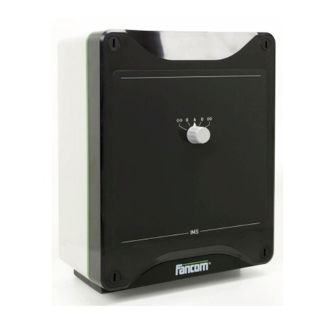
ITM-iF
G
MANUAL NHANDLEIDING D
ANLEITUNG
GND

N.B.: The original, authentic version of this manual is the English version produced by Fancom B.V. or one of its
daughter companies (referred to further as Fancom). Any modifications introduced to this manual by third parties
have neitherbeen checkednor approved by Fancom. Modifications are taken by Fancomto include translations into
languages other than English and the insertion and/or deletion of text and/or illustrations to/from the original
contents. Fancom cannot be held liable for any damages, injury, guarantee claims and other claims relating to this
type of modification, in as far as these modifications result in a content that differs from the original English version
of this manual produced by Fancom. For the latest information about product installation and operation, please
contact the customerservice dept. and/or the technical service dept. of the Fancom company concerned. In spite of
the care taken when compilingthis manual, if you should discover any errors, please inform Fancom B.V. in writing.
Fancom B.V., PO Box 7131, 5980 AC Panningen (the Netherlands).
Copyright © 2014 Fancom B.V.
Panningen (the Netherlands)
All rights reserved. Nothing from thismanual may be copied,distributed or translated into other languages, partly or
wholly, without express prior written permission from Fancom. Fancom reserves the right to modify this manual
without notice. Fancom can give no guarantee, neither implicit nor explicit, for this manual. All risks are for the user.
This manual has been compiled with the utmost care. If, however, you should discover an error, please inform
Fancom B.V.
Art.Nr. 35911850
GB140401
Gnd

Gnd
i
g
Table of contents
1. General introduction .................................................................................................................................. 1
1.1 How to use this manual..................................................................................................................1
1.2 Fancom helpdesk........................................................................................................................... 1
1.3 Safety instructions and warnings....................................................................................................2
2. Possibilities................................................................................................................................................. 3
2.1 ProFlow/NatuFlow..........................................................................................................................3
2.2 Remote I/O-module ........................................................................................................................3
3. Installing the ITM-iF.................................................................................................................................... 4
3.1 Mounting the ITM-iF........................................................................................................................4
3.2 Connecting the ITM-iF....................................................................................................................4
3.3 Testing the ITM-iF ..........................................................................................................................8
4. Using the ITM-iF.......................................................................................................................................... 9
4.1 Setting the knob..............................................................................................................................9
4.2 Display............................................................................................................................................9
5. Adjusting the ITM-iF................................................................................................................................. 10
5.1 General......................................................................................................................................... 10
5.2 Adjusting the 1% fan control output.............................................................................................. 10
5.3 Adjusting the maximum revolutions.............................................................................................. 11
5.4 Adjusting the control input ............................................................................................................ 11
6. Alarms ....................................................................................................................................................... 13
7. Technical specifications .......................................................................................................................... 14
8. Connection diagram................................................................................................................................. 15
9. Appendix: EG declaration of conformity................................................................................................ 16

Gnd
1
g
1. General introduction
This manual has been compiled with the utmost care. If, however, you should discover an error, please inform
Fancom B.V.
1.1 How to use this manual
The following symbols are used in this manual:
Tips and suggestions.
Note providing recommendations and additional information.
Warning indicating damage to the product if you do not follow procedures carefully.
Warning indicating danger to humans or animals.
Electrical shock hazard. Danger to humans and animals.
Example of a practical application of the described functionality.
Calculation example.
1.2 Fancom helpdesk
For any questions and support, please contact the local Fancom Sales & Service Center.

Gnd
2
g
1.3 Safety instructions and warnings
Before installing and commissioning the ITM-iF, read the safety instructions, provisions and conditions carefully.
This paragraph contains a number of general safety instructions. The installation of the device and remedying of any
malfunctions should be performed by a certified electrical installer according to the applicable norms. The guarantee
does not apply if this product is installed in any other way than is indicated by Fancom.
Disconnect power before installation.
Prevent electrostatic discharge (ESD) when working on the ITM-iF. Ensure that the workplace is clean
and dry.
Use correct wires as shown in the connection diagrams.
Make all wiring connections and check them before applying power. Incorrect connections can cause
permanent damage.
Make sure that the ITM-iF is well and properly grounded according to the guidelines.
Never place the ITM-iF in a place where the weather has direct influence (not in the sun, not in places
where the temperature can rise sharply etc.).
Inspect the ITM-iF periodically for any damages. Notify your installation technician immediately of any
damages. A damaged ITM-iF is unsafe!
Do not use water or high pressure cleaners for lengthy periods.
It is advisable not to switch off the ITM-iF. This could lead to condensation caused by cooling down.

Gnd
3
g
2. Possibilities
Set the type of control required using dipswitch 6, 7 and 8.
2.1 ProFlow/NatuFlow
The ITM-iF controls the ventilation in a section by measuring the air flow (DSR feedback signal) and by controlling
the I-fan and the valve of the ATM unit.
The ITM-iF can be used as:
1. Energy saving mechanical ventilation system (no possibility to switch to natural ventilation)
2. Energy saving mechanical. & natural ventilation system (possible to switch to natural ventilation)
3. Traditional mechanical ventilation system (no possibility to switch to natural ventilation, fan runs at higher
speed)
4. Mechanical several units in same room (no possibility to switch to natural ventilation)
2.2 Remote I/O-module
The climate controller controls the ventilation in the section by directly controlling the outputs of the ITM-iF.

Gnd
4
g
3. Installing the ITM-iF
Install the ITM-iF and associated components as follows:
1. Mount the ITM-iF (see page 4)
2. Connect the ITM-iF (see page 4)
3. Test the ITM-iF (see page 8)
3.1 Mounting the ITM-iF
When mounting/installing the ITM-iF, the following should be observed:
Never mount the ITM-iF in a room where animals are present because of the (manual) control.
Place the ITM-iF at such a height that the manual control can be used.
Mount the ITM-iF on a flat surface.
Make sure that the gland nuts are at the bottom of the ITM-iF.
Seal all gland nuts after connection of the ITM-iF to prevent entry of dust, aggressive gases and/or
humidity
3.2 Connecting the ITM-iF
Connecting as an I/O network module
1. Set an I/O-address using dipswitches 1 thru 5. All the I/O-network modules in an I/O-network should have a
unique address.
2. Choose the type of control using dipswitches 6, 7 and 8.
3. When all settings and calibration values are set in the climate controller no adjustment is necessary. Otherwise
adjust the ITM-iF according to the procedures described.
Do not forget to terminate the beginning and end of the I/O-net with a 120 Ω resistance. This can be
activated on the ITM-iF by placing a jumper.
Connecting as a traditional end station
1. Set the I/O-address to 0 using dipswitches 1 thru 5.
2. Remove jumpers TEMP so the ITM-iF can be used with 10-0Vdc analog control.
3. Choose the type of control using dipswitches 6, 7 and 8.
4. Adjust the ITM-iF according to the procedures described.
Do not forget to terminate the beginning and end of the I/O-net with a 120 Ω resistance. This can be
activated on the ITM-iF by placing a jumper.

Gnd
5
g
Settings
I/O address
Control type
I/O
adrr.
DIP 1
DIP 2
DIP 3
DIP 4
DIP 5
DIP 6
DIP 7
DIP 8
Control type
AN
On
On
On
On
On
On
On
On
CentralFlow (ATM with DSR)
1
Off
On
On
On
On
On
On
Off
AT(M) without DSR
2
On
Off
On
On
On
On
Off
On
NatuFlow / ProFlow direct
(analog output direct with
DSR-feedback)
3
Off
Off
On
On
On
4
On
On
Off
On
On
On
Off
Off
NatuFlow / ProFlow direct with
inverted manual operation
(analog output 10-0V direct
with DSR-feedback)
5
Off
On
Off
On
On
6
On
Off
Off
On
On
7
Off
Off
Off
On
On
8
On
On
On
Off
On
Off
On
On
Energy saving mechanical
9
Off
On
On
Off
On
Off
On
Off
Energy saving mech. & natural
10
On
Off
On
Off
On
Off
Off
On
Traditional mechanical
11
Off
Off
On
Off
On
Off
Off
Off
Mechanical several units
12
On
On
Off
Off
On
13
Off
On
Off
Off
On
Adjustment
14
On
Off
Off
Off
On
DIP 9*
DIP
10*
15
Off
Off
Off
Off
On
On
On
No adjustment (working position)
16
On
On
On
On
Off
Off
On
Adjust control input
17
Off
On
On
On
Off
On
Off
Adjust 1% fan control output
18
On
Off
On
On
Off
Off
Off
Adjust max. revolutions
19
Off
Off
On
On
Off
* Change dipswitch settings 9 and 10 one at the time and
not simultaneously!
20
On
On
Off
On
Off
21
Off
On
Off
On
Off
22
On
Off
Off
On
Off
23
Off
Off
Off
On
Off
24
On
On
On
Off
Off
25
Off
On
On
Off
Off
26
On
Off
On
Off
Off
27
Off
Off
On
Off
Off
28
On
On
Off
Off
Off
29
Off
On
Off
Off
Off
30
On
Off
Off
Off
Off
31
Off
Off
Off
Off
Off

Gnd
6
g
Item DIP Switch Control
A
Central Flow (PROLOW ENDSTATION)
•Central flow to control ATM unit (Vortex damper and
measuring fan DSR). Only with Lumina 20/21 and
Lumina 17 controller.
B
AT without DSR (PROFLOW DIRECT)
•Direct control. [%] in = [%] out, using with control AT
unit, (vortex damper without measuring fan DSR).
C
NatuFlow/ProFlow direct
•Analog output 0-10Volt direct with DSR-
feedback Only
possible with Lumina 20/21 and Lumina 17 controller
(PROFLOW DIRECT)
D
NatuFlow/ProFlow direct (with inverted manual
operation)
•Analog output 10-
0Volt direct with DSR feedback. Only
possible with Lumina 20/21 and Lumina 17 controller
(PROFLOW DIRECT)

Gnd
7
g
E
Energy saving mechanical ventilation.
•No possibility to switch to natural ventilation.
•iFan connection to extra Analog output of PWM2A
board.
•Use the control 10-0Volt at Lumina 17, Lumina 21,
Lumina 37, Lumina 38
•No DSR readout or calibration on the controller with
10-0V. When control is 10-
0V, calibration only possible
on ITM-iF itself by dipswitch 9 and 10 (see manual).
•When ITM-
iF controlled by Lumina 37 or Lumina 38 on
I/O-Net then there is no read out of the DSR feedback
on those controllers. Only possible with ITM-iF control
by I/O net with Lumina 21 or Lumina 17. (PROFLOW
ENDSTATION)
•ITM-iF control by I/O-Net on Lumina 21 or Lumina 17,
calibration is possible on the Lumina 21 of Lumina 17.
This is not possible by Lumina 37 or Lumina 38
F
Energy saving mechanical ventilation and natural vent.
(PROFLOW ENDSTATION)
•
The same as energy saving mechanical ventilation with
the possibility to switch over to natural ventilation.
G
Traditional mechanical ventilation (PROFLOW
ENDSTATION)
•
The same as energy saving mechanical ventilation with
no possibility to switch over to natural ventilation.
•In this mode the iFan will control on a higher speed.
H
Mechanical with several units (PROFLOW
ENDSTATION)
•
The same as energy saving mechanical ventilation with
no possibility to switch over to natural ventilation.
•Use this mode when more iFans with ATM units
connected parallel in one house, for example ridge
ventilation in a poultry house.

Gnd
8
g
I/O-network
Possibility of communication via the I/O-network. One control computer and a maximum of 31 network modules may
be connected to the I/Onetwork. Each connected network module hasa unique address. After an address has been
changed, the network module should always be restarted (power off-on).
In-/output type ITM-iF address . sequence number
Ventilation (analog)
“ITM-iF address” . 1
Relay output 1
“ITM-iF address” . 1
Relay output 2
“ITM-iF address” . 2
Analog measurement (temp.)
“ITM-iF address” . 1
RPM feedback-measurement
“ITM-iF address” . 1
Direct analog output 1
“ITM-iF address” . 1
Direct analog output 2
“ITM-iF address” . 2
The ITM-
iF can be connected to a PFB+battery. If the 24Vac power supply fails, it automatically switches
over to 24Vdc. In that case the analog outputs of the ITM-iF are controlled on 5V. Relays are not
controlled.
3.3 Testing the ITM-iF
1. Check whether the ITM-iF has been connected correctly.
2. Check whether the ITM-iF works optimally.

Gnd
9
g
4. Using the ITM-iF
4.1 Setting the knob
The knob on the front of the ITM-iF is used to set the ATM-unit to:
•Automatic (A) or
•Manual (M)
4.2 Display
A key is positioned on the front panel.
If this key is pressed, the following will be displayed alternately:
•Temperature
Own temperature measurement of the ITM-iF, without offsets of
the control computer, without averaging of other values (only
when controlled via the IO-network).
•Control and measured value ventilation
The control value is the control of the ITM-iF (ventilation position
or position of analogue output) measured value based on the
calibration value in the ITM-iF.
If the key is not used, then the temperature readout will be displayed again, 30 seconds after the key was used for
the last time.
If the rotary knob is set to manual (M), the display will flash.
When type of control is CentralFlow, only the vortex damper can be controlled manually.
When type of control is ProFlow/NatuFlow, both I-fan and vortex damper can be controlled manually.

Gnd
10
g
5. Adjusting the ITM-iF
5.1 General
Before the ITM-iF can be used, the Triac, the maximum number of revolutions and the control input should first be
adjusted, depending on the setting. The position of the dipswitches is important for this adjustment (see table
below).
Adjustment of: DIP 9 DIP 10
Adjust 1% fan control output
On
Off
Maximum revolutions
Off
Off
Control input
Off
On
5.2 Adjusting the 1% fan control output
Only adjust the 1% fan control output to increase the minimum fan speed. When an I-fan is used, this is
not necessary.
1. Open the lid of the ITM-A housing.
2. Position the dipswitches (9 =On, 10 =Off).
3. Turn the rotary knob on the front to its “minimum position”, so that the fan is running at the desired minimum
speed (this depends on installation).
4. The red led (L1) flashes: briefly on, long period off. The green led (L2) is off. This means that the 1% is be
adjusted.
5. When the required voltage has been set, confirm this by pressing the calibration knob. The green led (L2)
flashes.
6. The green led will go off after five seconds, 1% adjustment has been completed.
7. The ITM-A has completed the 1% adjustment after five seconds. The status of adjustment can now be shown:
- Green led on : Adjustment successful.
- Red led on : Adjustment unsuccessful. Adjust again.
Control vortex damper
The ITM-iF also controls the analog output for the control or adjustment of the vortex damper. The output of the
analog output is 1% during 1% adjustment.
After adjustment set dipswitches 9 and 10 to ON and the knob to A.

Gnd
11
g
5.3 Adjusting the maximum revolutions
Only applicable when using DSR-feedback.
Method
1. Open the lid of the ITM-iF housing.
2. Position the dipswitches (9 =Off, 10 =Off) and set the knob and the switch on the front to A.
3. Press the knob to start adjustment.
4. The vortex damper will open, the fan will run at high speed after 10 seconds. The red led (L1) is off. The green
led (L2) flashes, to indicate that adjustment has started. The fan will run at high speed for a maximum of 60
seconds.
5. Wait until the fan has come to a standstill.
6. Check whether adjustment has been successful:
- Green led on : Adjustment successful.
- Red led on : Adjustment unsuccessful. The most common cause is that the ITM-iF has
measured none or too few pulses. Check the DSR-feedback sensor and
repeat the adjustment procedure.
After adjustment set dipswitches 9 and 10 to ON.
5.4 Adjusting the control input
Not applicable when using the I/O-network.
Method 1% adjustment
1. Open the lid of the ITM-iF housing.
2. Position the dipswitches (9=Off, 10=On) and remove the jumpers TEMP.
3. Set the analog output of the controller to 1%. Check the voltage; this should be between 9 and 10V (with a
0-10V control this is between 0.1V and 1V).
4. Turn the knob on the front to its minimum position. The red led (L1) flashes: briefly on, longer period off. The
green led (L2) is off. This means that the 1% is to be adjusted.
5. Confirm the 1% adjustment by pressing the knob. The green led (L2) flashes.
6. The green led (L2) will go off after five seconds. The ITM-iF has completed the 1% adjustment.

Gnd
12
g
Method 99% adjustment
1. Set the analog output of the controller to 99%. Check the voltage, this should be between 0.1 and 1V (with a
0-10V control this is between is 9V and 10V).
2. Turn the knob on the front to its maximum position. The red led (L1) flashes: longer period on, briefly off. The
green led (L2) is off. This means that the 99% will be adjusted.
3. Confirm the 99% adjustment by pressing the knob. The green led (L2) flashes.
4. The ITM-iF has completed adjustment after five seconds. The status of the adjustment can now be shown.
- Green led on : Adjustment successful.
- Red led on : Adjustment unsuccessful. The most common cause is that the ITM-iF has
measured none or too few pulses. Check the DSR-feedback sensor and
repeat the adjustment procedure.
After adjustment set dipswitches 9 and 10 to ON and the knob to A.

Gnd
13
g
6. Alarms
Alarm indication
Led 1 and Led 2 flash simultaneously.
Backup alarm
Led 1 and Led 2 flash alternately.
Memory alarm

Gnd
14
g
7. Technical specifications
Power supply
Mains voltage
24Vac (-10%, +10%)
Mains frequency
50/60Hz
Maximum power consumption
5VA
Fuse electronics
see connection diagram
Inputs
Analog In
Voltage
0-10Vdc
Temperature sensor type S7
-9.9°C to +99.9°C
DSR-feedback
4 pulses per revolution
max. frequency: 200Hz
Knob
Adjust ventilation between 0 – 100%
Outputs
Power outage relay
30Vac/60Vdc, max. 2A
Relay 2×
30Vac/60Vdc, max. 2A
Analog out
10-0Vdc
Analog out1
10-0Vdc
Housing
Plastic housing with screw-on lid
IP54
Dimensions (l×w×h)
300×240×140mm
Weight (unpacked)
2.3kg
Ambient climate
Operating temperature range
0
°
C to +40
°
C
Storage temperature range
–10
°
C to 50
°
C
Relative humidity
< 95%, uncondensed

Gnd
15
g
8. Connection diagram
VL POWER BOARD
AI Temperature (type S7) / Analog control
AO Control vortex damper
-S+ DSR sensor
RL1/RL2 Relays
PWM2A
AO1 Control I-fan

Gnd
16
g
9. Appendix: EG declaration of conformity
Manufacturer: Fancom B.V.
Address: Industrieterrein 34
City: Panningen (the Netherlands)
Hereby declares that the: ITM-iF
Complies with the provisions of the:
1. EMC directive 2004/108/EC
Emission according to NEN-EN-IEC 61326-1: 2013
Immunity according to NEN-EN-IEC 61326-1: 2013
Place: Panningen Date: 01-04-2014
Paul Smits
Managing Director

N.B.: De originele, authentieke versie van deze handleiding is de door Fancom B.V. of door een van haar
dochterondernemingen (verder aangeduid als Fancom) geproduceerde Engelstalige versie. Achteraf door derden
aangebrachte wijzigingen in deze handleiding zijn door Fancom noch gecontroleerd, noch goedgekeurd. Onder
wijzigingen verstaat Fancom o.a. het vertalen in een andere taal dan het Engels en het toevoegen en/of verwijderen
van tekst en/of illustraties aan/uit de originele inhoud. U kunt Fancom niet aansprakelijk stellen voor schade, letsel,
garantieclaims en andere claims die verband houden met dit soort wijzigingen, voor zover deze wijzigingen
resulteren in een inhoud die afwijkt van de authentieke door Fancom geproduceerde Engelstalige versie van deze
handleiding. Voor actuele informatie over productinstallatie en bediening, neem contact op met de klantenservice
en/of technische serviceafdeling van de betreffende Fancom-onderneming. Mocht u onverhoopt toch een fout
ontdekken, dan vragen wij u vriendelijk Fancom B.V. hiervan schriftelijk in kennis te stellen. Fancom B.V., Postbus
7131, 5980 AC Panningen (the Netherlands)
Copyright © 2014 Fancom B.V.
Panningen (the Netherlands)
Alle rechten zijn voorbehouden. Niets uit deze handleiding mag worden gekopieerd, gedistribueerd of vertaald in
andere talen, geheel of gedeeltelijk, zonder voorafgaande schriftelijke toestemming van Fancom. Fancom houdt
zich het recht voor om wijzigingen in de handleiding aan te brengen. Fancom kan echter geen garantie geven,
impliciet noch expliciet, voor deze handleiding. Het risico hiervan ligt volledig bij de gebruiker.
Deze handleiding is met de grootst mogelijke zorg samengesteld. Mocht u onverhoopt toch een fout ontdekken, dan
vragen wij u vriendelijk Fancom B.V. hiervan in kennis te stellen.
Art.nr. 35911850
NL140401
gNd
This manual suits for next models
1
Table of contents
Languages:
Other Fancom Control System manuals

Fancom
Fancom 743 User manual

Fancom
Fancom 750 User manual

Fancom
Fancom WEBLINKBOX VERSION A2 User manual

Fancom
Fancom LUMINA 41 User manual

Fancom
Fancom INTELLITEK User manual

Fancom
Fancom FB.1 User manual

Fancom
Fancom Lumina 35 User manual

Fancom
Fancom LUMINA 71 User manual

Fancom
Fancom VLR.6 User manual

Fancom
Fancom 743 User guide
Popular Control System manuals by other brands

ABB
ABB ACS800-02 Hardware manual

flamco
flamco Flexcon M-K Series Installation and operating instructions

HEIDENHAIN
HEIDENHAIN ITNC 530 - CONVERSATIONAL PROGRAMMING operating instructions

Sargent
Sargent EC400 Series System instructions

btsr
btsr SMART CLEARER operating manual

Moniteq
Moniteq Crypto Lock CC-8521BN instruction manual