Fein GRIT GIMS150 User manual

© C. & E. Fein GmbH. Printed in Denmark. Abbildungen unverbindlich. Technische Änderungen vorbehalten. 3 94 10 014 00 1 BY 2013.01Z DE.
FEIN Service
C. & E. Fein GmbH
Hans-Fein-Straße 81
D-73529 Schwäbisch Gmünd-Bargau
www.fein.com
2011/65/EU, 2006/42/EG,
2004/108/EG (2016-04-19), 2014/30/EU (2016-04-20 ),
2006/95/EG (2016-04-19), 2014/35/EU (2016-04-20 )
Lars Graver
Mechanical Engineer Søren Strunge
Managing Director
GIMS150 7 902 14 00 40 3
GIMS1502V 7 902 14 00 23 3
GIMS1505V6 7 902 14 09 57 3
GIMS75 7 902 13 00 40 3
GIMS752V 7 902 13 00 23 3
GIMS755V6 7 902 13 09 57 3
3 94 10 014 00 1 - Titel.fm Seite 1 Dienstag, 20. Oktober 2015 9:29 09

2
Deutsch _____________ Betriebsanleitung__________________
English______________ Instruction Manual_________________
Français_____________ Notice d’utilisation_________________
Italiano _____________ Istruzioni per l’uso _________________
Nederlands___________ Gebruiksaanwijzing ________________
Español _____________ Instrucciones de uso _______________
Português ___________ Instruções de serviço _______________
EÏÏËÓÈο ____________ √‰ËÁ›Â˜ ¯Ú‹Û˘ ___________________
Dansk ______________ Driftsvejledning ___________________
Norsk ______________ Driftsinstruks ____________________
Svenska_____________ Bruksanvisning ___________________
Suomi ______________ Käyttöohje_______________________
Magyar _____________ Üzemeltetési utasítás _______________
âesky ______________ Návod k obsluze __________________
Slovensky ___________ Návod na pouÏitie _________________
Polski ______________ Instrukcja eksploatacji ______________
На русском языке __ Руководство по эксплуатации___
______________
________
6
11
13
16
18
21
23
25
28
30
32
34
36
39
41
44
47
50
3 94 10 014 00 1.book Seite 2 Donnerstag, 31. Januar 2013 9:01 09

3
100,00 mm
123
6
5
4
1
23
8
12
14
2
1
910
11
13
7
3 94 10 014 00 1.book Seite 3 Donnerstag, 31. Januar 2013 9:01 09

4
15
16 17
18
20
3
19
3 94 10 014 00 1.book Seite 4 Donnerstag, 31. Januar 2013 9:01 09

5
45
67
89
12
16
21
22
23
19
3 94 10 014 00 1.book Seite 5 Donnerstag, 31. Januar 2013 9:01 09

6
de
Originalbetriebsanleitung Fahrgestell.
Verwendete Symbole, Abkürzungen und
Begriffe.
Die in dieser Betriebsanleitung und ggf. auf dem Gerät
verwendeten Symbole dienen dazu, Ihre Aufmerksam-
keit auf mögliche Gefährdungen bei der Arbeit mit die-
sem Gerät zu lenken.
Zu Ihrer Sicherheit.
Verwenden Sie dieses Fahrgestell nicht, bevor Sie
diese Betriebsanleitung gründlich gelesen und voll-
ständig verstanden haben, einschließlich der Abbil-
dungen, Spezifikationen und Sicherheitsregeln.
Lesen und beachten Sie die Betriebsanleitung der
Maschine, die auf dieses Fahrgestell montiert wer-
den soll.
Diese Betriebsanleitung zum späteren Gebrauch aufbe-
wahren und bei einer Weitergabe oder Veräußerung der
Maschine überreichen.
Verwenden Sie zur Montage der Maschine auf dem Fahrge-
stell das passende Befestigungsmaterial.
Eine fehlerhafte
Montage kann dazu führen, dass sich die Maschine wäh-
rend des Arbeitsvorganges vom Fahrgestell löst und
schwere Unfälle verursacht.
Stellen Sie vor dem Einschalten sicher, dass alle Spannhe-
bel am Fahrgestell gut festgezogen sind.
Senkt sich die
Maschine während des Arbeitsvorganges plötzlich ab,
kann dies zu schweren Unfällen führen.
Tragen Sie persönliche Schutzausrüstung. Verwen-
den Sie je nach Anwendung Vollgesichtsschutz,
Augenschutz oder Schutzbrille. Soweit angemessen,
tragen Sie Staubmaske, Gehörschutz, Schutzhand-
schuhe oder Spezialschürze, die kleine Schleif- und
Materialpartikel von Ihnen fernhält.
Die Augen sol-
len vor herumfliegenden Fremdkörpern geschützt
werden, die bei verschiedenen Anwendungen ent-
stehen. Staub- oder Atemschutzmaske müssen den
bei der Anwendung entstehenden Staub filtern.
Wenn Sie lange lautem Lärm ausgesetzt sind, kön-
nen Sie einen Hörverlust erleiden.
Arbeiten Sie nur auf waagrechten Flächen.
Auf schrägen
Flächen kann die Maschine außer Kontrolle geraten.
Das Verlängerungskabel während des Arbeitsvorganges
immer von der Arbeitsstelle wegführen.
Wird das Netzka-
bel überfahren, gequetscht oder beschädigt, besteht die
Gefahr eines elektrischen Schlags!
Bei Wartungs- Montage und Einstellarbeiten den Netzste-
cker ziehen!
Wird die Maschine unbeabsichtigt einge-
schaltet, kann dies zu Unfällen führen.
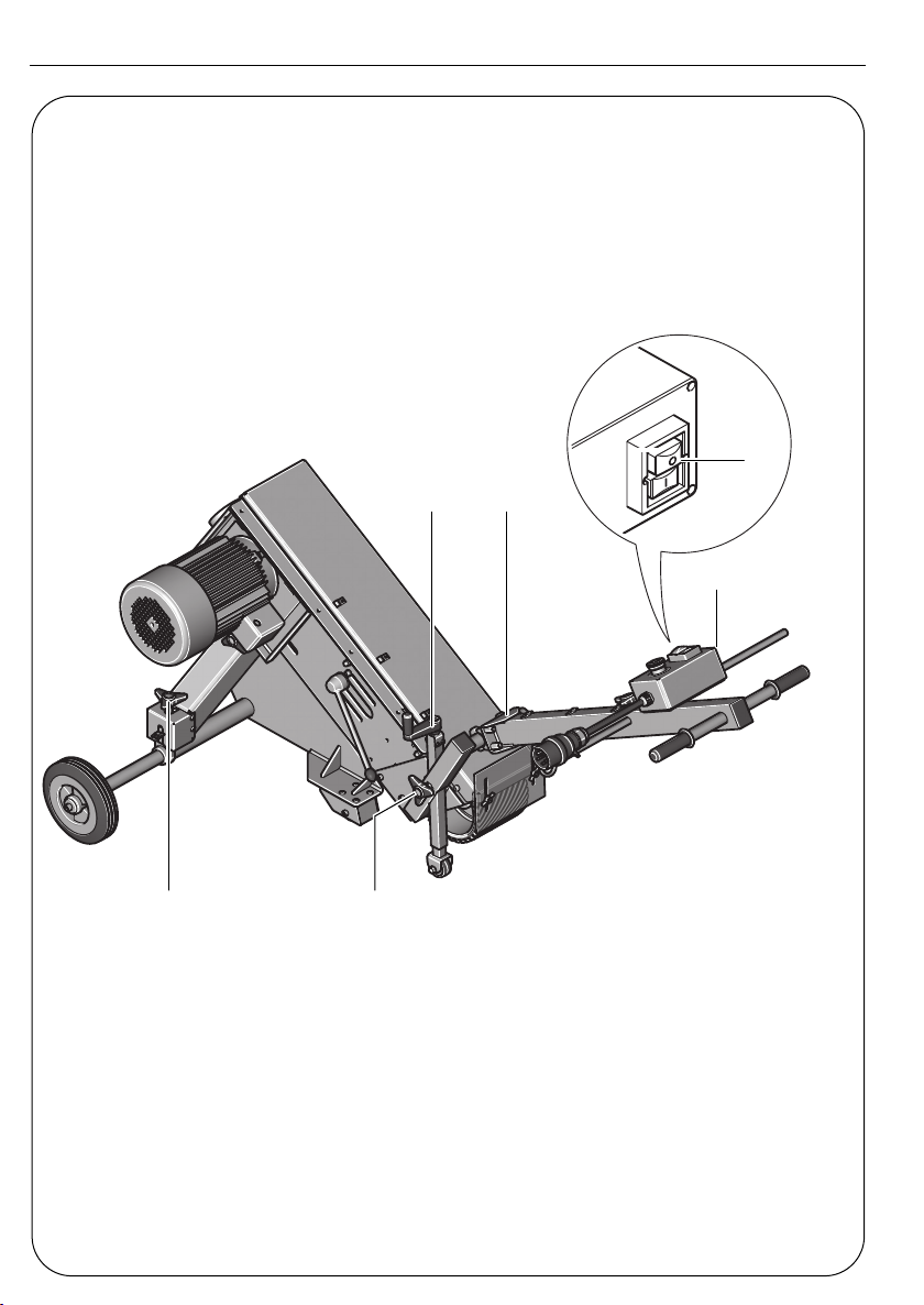
Auf einen Blick.
1 Befestigungsschraube
2 Unterlegscheibe
3 Rad
4 Achse
5 Feststellhebel, Achse
6 Auflagefläche
7 Befestigungsschrauben für Halteplatte
8 Schraube
9 Halteplatte
10 Halteschaft
11 Kabelführung
12 Feststellschraube
13 Lenkstange
14 Befestigungsschrauben für Bandschleifer (4x)
15 Ein-/Ausschalter
16 Kurbel für Bandschleifer-Höheneinstellung
17 Kabelbinder
18 Elektrischer Schaltkasten
19 Sterndrehschraube für Paralleleinstellung
20 Feststellschraube
21 Schraube für Tiefenanschlag
22 Schraube für Höhenanschlag
23 Kurbel für Hubkrafteinstellung
Bestimmung der Maschine.
Das Fahrgestell ist in Verbindung mit GRIT Schleifmaschi-
nen GI 75/150 zum Schleifen von Bodenflächen
bestimmt.
Montageanweisungen.
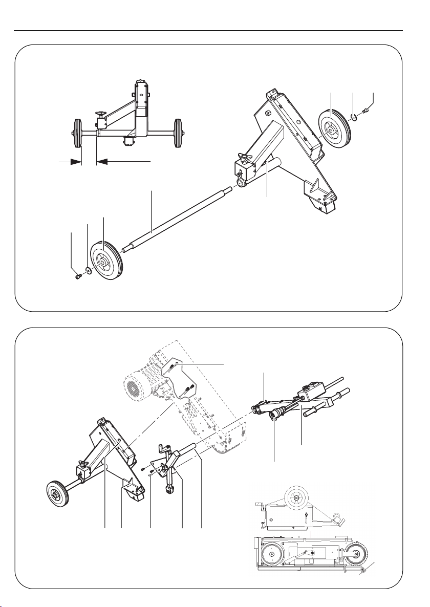
Fahrwerk montieren (Bild 1).
➤
Stecken Sie die Achse (4) durch das Achsrohr. Befes-
tigen Sie die Räder (3) mit den Schrauben (1) und
Unterlegscheiben (2) an der Achse.
➤
Fixieren Sie die Achse (4) mit der Feststellhebel (5)
so, dass sich zwischen Radnabe und Achsrohr ein
Abstand von ca. 100 mm ergibt.
Bandschleifer auf Fahrgestell montieren (Bild 2).
➤
Entfernen Sie am Bandschleifer den Spänekasten,
den Schleiftisch, sowie die entsprechenden Schrau-
ben (siehe Betriebsanleitung Bandschleifer).
Wegen erhöhter Unfallgefahr müssen die folgenden
Arbeitsschritte von mehreren Personen durchgeführt
werden:
➤
Öffnen und entfernen Sie das Seitenteil des Band-
schleifers.
➤
Legen Sie den Bandschleifer mit der Kopfseite auf
den Boden. Verwenden Sie zur Vermeidung von
Kratzern oder Beschädigungen eine geeignete
Unterlage.
➤
Setzen Sie das Fahrgestell auf den Bandschleifer auf.
➤
Richten Sie das Fahrgestell über den Bohrungen aus.
Befestigen Sie das Fahrgestell mit den Schrau-
ben (14) am Bandschleifer.
➤
Stellen Sie die gesamte Einheit auf die Räder (3).
Symbol Begriff, Bedeutung
➤
Aktion
Dokumentation lesen
Allgemeines Gebotszeichen
Warnung vor Gefahr
3 94 10 014 00 1.book Seite 6 Donnerstag, 31. Januar 2013 9:01 09

7
de
➤
Montieren Sie die Halteplatte (9) mit den Schrau-
ben (7) und (8) an den vorderen Teil des Bandschlei-
fers.
➤
Schieben Sie die Lenkstange (13) auf den Halte-
schaft (10) und sichern Sie diese mit den vier Fest-
stellschrauben (12) des Haltebügels.
Elektroanschluss.
Stellen Sie vor dem Anschluss an das Stromnetz
sicher, dass der Bandschleifer ausgeschaltet ist
(Taste „0“ am Sicherheitsschalter muss gedrückt
sein!).
➤
Schließen Sie den Schaltkasten (18) mit einem Ver-
längerungskabel an das Stromnetz an.
➤
Ziehen Sie das Verlängerungskabel durch die Kabel-
führung (11).
Einstellungen.
Ziehen Sie vor allen Arbeiten an der Maschine den
Stecker aus der Steckdose.
Lenkstange einstellen (Bilder 3/4).
➤Die vier Schrauben (12) lösen und die Lenkstange
auf die gewünschte Arbeitshöhe einstellen. Alle
Schrauben in dieser Position festziehen.
Schleifabtrag einstellen (Bilder 3/5).
➤Stellen Sie den Bandschleifer mit der Sterndreh-
schraube (20) ungefähr auf Arbeitshöhe ein.
➤Stellen Sie mit der Kurbel (16) den Abstand zwi-
schen Schleifband und Oberfläche ein. Der Schlei-
fabtrag kann auch während des Arbeitsvorganges
reguliert werden.
Tiefenanschlag einstellen (Bild 6).
➤Die Schraube (21) lösen.
➤Mit der Kurbel (16) den Bandschleifer auf den Schlei-
fabtrag einstellen der maximal erreicht werden soll.
➤Den Tiefenanschlag mit der Schraube (21) in dieser
Position fixieren.
Höhenanschlag einstellen (Bild 7).
➤Die Lenkstange nach oben schwenken, so dass sich
der Bandschleifer nach oben bewegt.
➤Mit der Schraube (22) kann die gewünschte
Schwenkhöhe eingestellt werden.
Hubkraft einstellen (Bild 8).
➤Mit der Kurbel (23) kann die erforderliche Hubraft
eingestellt werden.
➤Die Hubkraft so einstellen, dass der Bandschleifer
leichtgängig abgesenkt werden kann und beim Anhe-
ben oder in Arbeitspausen selbsttätig in der oberen
Position gehalten wird.
Parallelität einstellen (Bild 9).
Für einen gleichmäßigen Schleifabtrag ist es erforderlich,
dass das Schleifband parallel zur Oberfläche läuft.
➤Justieren Sie den Bandlauf mit der Sterndreh-
schraube (19).
Betriebsanweisungen.
Einschalten:
➤Sicherheitsschalter entriegeln. Taste „I“ (15) drü-
cken.
Ausschalten:
➤Sicherheitsschalter entriegeln. Taste „0“ (15) drü-
cken.
Die Maschine läuft nach dem Ausschalten ca.
50 sek. nach.
Sicherheitsschalter:
➤Drücken Sie in Gefahrensituationen den roten
Sicherheitsschalter um die Maschine auszuschalten.
Arbeitshinweise
➤Führen Sie das Fahrgestell an die Arbeitsstelle.
➤Schalten Sie den Bandschleifer ein und ziehen Sie
den Lenkstangenhebel in Arbeitsposition.
➤Führen Sie den Bandschleifer mit gleichmäßiger
Geschwindigkeit über die zu schleifende Fläche.
➤Schwenken Sie die Lenkstange nach Beendigung des
Arbeitsvorganges nach oben und schalten Sie den
Bandschleifer aus.
Instandhaltung und Kundendienst.
Eine Instandsetzung darf nur durch eine Fachkraft
nach den gültigen Vorschriften durchgeführt wer-
den.
Zur Instandsetzung empfehlen wir den FEIN-Kunden-
dienst, die FEIN-Vertragswerkstätte und die FEIN-Ver-
tretungen.
Die aktuelle Ersatzteilliste dieses Elektrowerkzeuges fin-
den Sie im Internet unter www.fein.com.
Gewährleistung und Garantie.
Die Gewährleistung auf das Erzeugnis gilt gemäß den
gesetzlichen Regelungen im Lande des Inverkehrbrin-
gens.
Darüber hinaus leistet FEIN Garantie entsprechend der
FEIN-Hersteller-Garantieerklärung. Details diesbezüglich
erfahren Sie bei Ihrem Fachhändler, der FEIN-Vertretung
in Ihrem Land oder beim FEIN-Kundendienst.
Konformitätserklärung.
Die Firma GRIT erklärt in alleiniger Verantwortung, dass
dieses Produkt den auf der letzten Seite dieser
Betriebsanleitung angegebenen einschlägigen Bestim-
mungen entspricht.
Originalsprache Englisch/Deutsch
Umweltschutz, Entsorgung.
Stationärmaschinen sollen gemäß nationalem Recht einer
umweltgerechten Wiederverwertung zugeführt werden.
3 94 10 014 00 1.book Seite 7 Donnerstag, 31. Januar 2013 9:01 09

8de
Technische Daten.
Anschlussschaltbilder.
Typ GIM75 Anlage 52
Typ GIM752V Anlage 52
Typ GIM150 Anlage 52
Typ GIM1502V Anlage 52
Typ GIMS75 GIMS752V GIMS150 GIMS1502V
Bestellnummer 7 902 13 12 40 3 7 902 13 12 23 3 7 902 14 12 40 3 7 902 14 12 23 3
Gewicht entsprechend
EPTA-Procedure
01/2003 115 115 126 126
Schutzklasse I/ I/ I/ I/
3 94 10 014 00 1.book Seite 8 Donnerstag, 31. Januar 2013 9:01 09

9
en
Original Instructions for wheeled carriage.
Symbols, abbreviations and terms used.
The symbols used in this Instruction Manual and possibly
on the wheeled carriage, serve to draw your attention to
possible hazards when working with the wheeled car-
riage.
For your safety.
Do not use this wheeled carriage before you have
thoroughly read and completely understood this
Instruction Manual, including the figures, specifica-
tions and safety regulations.
Read and observe the Instruction Manual of the
machine which is to be mounted on this wheeled
carriage.
These operating instructions should be kept for later use
and enclosed with the power tool, should it be passed on
or sold.
Use appropriate fastening material when mounting the
machine to the wheeled carriage. When mounted incor-
rectly, the machine can come loose from the wheeled
carriage and cause serious accidents.
Before switching on, ensure that all clamping levers on the
wheeled carriage are firmly tightened.Sudden lowering of
the machine during the work procedure can lead to seri-
ous injuries.
Wear personal protective equipment. Depending on
application, use face shield, safety goggles or safety
glasses. As appropriate, wear dust mask, hearing
protectors, gloves and workshop apron capable of
stopping small abrasive or workpiece fragments.
The eye protection must be capable of stopping
flying debris generated by various operations. The
dust mask or respirator must be capable of filtrat-
ing particles generated by your operation. Pro-
longed exposure to high intensity noise may cause
hearing loss.
Work only on level surfaces. On inclined surfaces, the
machine can get out of control.
During the working process, always conduct the extension
cord away from the work location. Danger of an electrical
shock when the mains cable is driven over, pinched,
crushed or damaged!
Pull out the mains plug for maintenance and repair!Switch-
ing the machine on unintentionally can lead to an electric
shock.
At a glance.
1 Fastening bolt
2 Washer
3 Wheel
4 Axle
5 Locking lever for axle
6 Supporting surface
7 Fastening bolts for holding plate
8 Bolt
9 Holding plate
10 Fastening shaft
11 Cable holder
12 Locking nuts
13 Handle bar
14 Fastening bolts for belt grinder (4x)
15 On/Off switch
16 Crank for height adjustment of belt grinder
17 Cable tie
18 Electrical switchbox
19 Star-knob bolt for parallel adjustment
20 Star-knob locking bolt
21 Screw for depth stop
22 Screw for height stop
23 Crank for adjustment of the lowering/lifting force
Intended use of the machine.
Together with the GI 75/150 GRIT sanding/grinding
machines, the wheeled carriage is intended for sanding/
grinding floor surfaces.
Mounting instructions.
Mounting the wheeled carriage (Figure 1).
➤Insert the axle (4) through the axle sleeve. Fasten the
wheels (3) to the axle with the bolts (1) and wash-
ers (2).
➤Lock the axle (4) with the locking lever (5) so that a
clearance of approx. 100 mm results between the
hub of the wheel and the axle sleeve.
Mounting the belt sander/grinder to the wheeled
carriage (Figure 2).
➤Dismount the dust collector, the grinding rest and
the corresponding screws from the belt grinder (see
Belt Grinder Instruction Manual).
Because of the increased danger of accidents, the
following work steps must be carried out by several
persons:
➤Open and remove the side cover of the belt grinder.
➤Place the belt grinder with the face side on the floor.
Underlay suitable padding in order to avoid scratches
or damage.
➤Place the wheeled carriage onto the belt grinder.
➤Align the wheeled carriage so that it fits over the drill
holes. Fasten the wheeled carriage to the belt grinder
with the fastening bolts (14).
➤Position the complete unit onto the wheels (3).
➤Mount the holding plate (9) with fastening bolts (7)
and (8) to the front part of the belt grinder.
Symbol Term, meaning
➤Action
Read documentation
General mandatory sign
Danger warning
3 94 10 014 00 1.book Seite 9 Donnerstag, 31. Januar 2013 9:01 09

10 en
➤Slide the cross bar (13) onto the fastening shaft (10)
and secure it with the four locking nuts (12) of the
fastening bracket.
Electrical connection.
Before connecting to the mains supply, make sure
that the belt sander is switched off (the “0” button of
the safety switch (emergency OFF pushbutton) must
be pressed!).
➤Connect the electrical switch box (18) to the mains
supply with an extension cord.
➤Place the extension cord in the cable holder (11).
Adjustments.
Before any work on the machine itself, pull the power
plug from the socket outlet.
Adjusting the handle bar (Figures 3/4).
➤Loosen the four locking nuts (12) and adjust the han-
dle bar to the required working height. Tighten all
nuts in this position.
Adjusting the rate of removal (Figures 3/5).
➤Adjust the belt grinder to the approx. working
height with the star-knob bolt (20).
➤Adjust the clearance between the sanding/grinding
belt and the floor surface with the crank (16). The
rate of removal can also be regulated during the
working procedure.
Setting the depth stop (Figure 6).
➤Loosen screw (21).
➤With the crank (16), adjust the belt grinder to the
maximal rate of removal to be achieved.
➤Lock the depth stop in this position with the
screw (21).
Adjusting the height stop (Figure 7).
➤Tilt the handle bar upward so that the belt grinder
moves upward.
➤The required tilting height can be adjusted with the
screw (22).
Adjusting the lowering/lifting force (Figure 8).
➤The required lowering/lifting force can be adjusted
with the crank (23).
➤Adjust the lowering/lifting force in such a manner
that the belt grinder can be lowered easily and is held
automatically in the upper position when tilting
upward or during work breaks.
Adjusting the parallelism (Figure 9).
For a uniform rate of removal, it is required that the sand-
ing/grinding belt runs parallel to the surface.
➤Adjust the run of the belt with the star-knob
bolt (19).
Operating instructions.
Switching ON:
➤Release the safety switch. Press the “I” (15) button.
Switching OFF:
➤Release the safety switch. Press the “0” (15) button.
After switching off, the machine runs on for
approx. 50 seconds.
Safety switch (emergency OFF switch):
➤In emergency situations, press the red safety switch
(emergency OFF switch) to switch the machine off.
Working instructions
➤Move the wheeled carriage to the working location.
➤Switch the belt grinder on and pull the handle bar
lever to the working position.
➤Move the belt grinder along the surface to be ground
with uniform speed.
➤After finishing the working procedure, tilt the handle
bar upward and switch the belt grinder off.
Repair and customer service.
Repairs may be carried out only by qualified per-
sons in conformity with the valid regulations.
For repairs, we recommend our FEIN customer service
centre, the FEIN authorised service centres and FEIN
agencies.
The current spare parts list for this power tool can be
found in the Internet at www.fein.com.
Warranty and liability.
The warranty for the product is valid in accordance with
the legal regulations in the country where it is marketed.
In addition, FEIN also provides a guarantee in accordance
with the FEIN manufacturer’s guarantee. For further
details on this, please contact your specialist dealer, your
national FEIN representative, or the FEIN customer serv-
ice centre.
Declaration of conformity.
GRIT declares itself solely responsible for this product
conforming with the relevant provisions given on the last
page of this Instruction Manual.
Original language English/German
Environmental protection, disposal.
Stationary machines should be sorted for environment-
friendly recycling in accordance with national laws.
3 94 10 014 00 1.book Seite 10 Donnerstag, 31. Januar 2013 9:01 09

11
en
Specifications.
Connection diagrams.
Typ GIM75 Appendix 52
Typ GIM752V Appendix 52
Typ GIM150 Appendix 52
Typ GIM1502V Appendix 52
Type GIMS75 GIMS752V GIMS150 GIMS1502V
Reference number 7 902 13 12 40 3 7 902 13 12 23 3 7 902 14 12 40 3 7 902 14 12 23 3
Weight according to EPTA-
Procedure 01/2003 115 115 126 126
Class of protection I/ I/ I/ I/
3 94 10 014 00 1.book Seite 11 Donnerstag, 31. Januar 2013 9:01 09

12 fr
Notice originale châssis.
Symboles, abréviations et termes utilisés.
Les symboles utilisés dans cette notice d’utilisation et, le
cas échéant, sur l’appareil, servent à attirer votre atten-
tion sur les dangers éventuels que comporte le travail
avec cet appareil.
Pour votre sécurité.
Ne pas utiliser ce châssis avant d’avoir soigneuse-
ment lu et complètement compris cette notice
d’utilisation, y compris les figures, les spécifications
et les règles de sécurité.
Lire et respecter les instructions d’utilisation de
l’appareil qui doit être monté sur ce châssis.
Gardez bien cette notice en vue d’une utilisation ulté-
rieure ; elle doit être jointe à l’appareil en cas de trans-
mission ou de vente à une tierce personne.
Utiliser des dispositifs de fixation appropriés pour monter
l’appareil sur le châssis. Un montage incorrect peut pro-
voquer de graves accidents causés par un appareil qui
s’est détaché du châssis pendant l’opération de travail.
Avant de mettre l’appareil en service, s’assurer que tous les
leviers de serrage sur le châssis sont bien serrés. Si l’appa-
reil s’abaisse soudainement pendant l’opération, ceci
peut provoquer de graves accidents.
Porter un équipement de protection individuelle. En
fonction de l’application, utiliser un écran facial, des
lunettes de sécurité ou des verres de sécurité. Le cas
échéant, utiliser un masque antipoussières, des pro-
tections auditives, des gants et un tablier capables
d’arrêter les petits fragments abrasifs ou des pièces
à usiner. La protection oculaire doit être capable
d’arrêter les débris volants produits par les diver-
ses opérations. Le masque antipoussières ou le res-
pirateur doit être capable de filtrer les particules
produites par vos travaux. L’exposition prolongée
aux bruits de forte intensité peut provoquer une
perte de l’audition.
Ne travailler que sur des surfaces horizontales. Sur des
surfaces inclinées, vous risquez de perdre le contrôle sur
l´appareil.
Lors du travail, toujours maintenir le câble de rallonge en
dehors de la zone de travail. Si le câble est écrasé, coincé
ou endommagé, il y a un risque de choc électrique !
Pour les travaux d’entretien, de montage et de réglage, reti-
rer la fiche de la prise de courant ! Le fait de mettre en
marche l’appareil par mégarde peut entraîner des acci-
dents.
Vue générale.
1 Vis de fixation
2 Rondelle
3 Roue
4 Essieu
5 Levier de blocage, essieu
6 Surface de support
7 Vis de fixation pour la plaque de fixation
8 Vis
9 Plaque de fixation
10 Tige
11 Cheminement du câble
12 Vis de blocage
13 Barre conductrice
14 Vis de fixation pour ponceuse à bande (4x)
15 Interrupteur Marche/Arrêt
16 Manivelle pour réglage de la hauteur de la ponceuse à
bande
17 Collier de câble
18 Boîte de commande électrique
19 Vis étoile pour réglage parallèle
20 Vis de blocage
21 Vis pour butée de profondeur
22 Vis pour butée de hauteur
23 Manivelle pour réglage de la puissance de levage
Utilisation de l’appareil.
Le châssis, avec les ponceuses GRIT GI 75/150 mm, est
conçu pour le ponçage de surfaces au sol.
Indications de montage.
Montage du châssis (Figure 1).
➤Faire passer l’essieu (4) à travers le tuyau d’essieu.
Fixer les roues (3) au moyen des vis (1) et des ron-
delles (2) sur l’essieu.
➤Bloquer l’essieu (4) au moyen du levier de blocage
(5) de sorte que la distance entre le moyeu de roue
et le tuyau d’essieu soit de 100 mm environ.
Montage de la ponceuse à bande sur le châssis
(Figure 2).
➤Retirer la boîte à copeaux de la ponceuse à bande
ainsi que la table de ponçage et les vis correspondan-
tes (voir Instructions d’utilisation ponceuse à bande).
En raison du risque élevé d’accident, les opérations
de travail suivantes doivent être effectuées par plu-
sieurs personnes :
➤Ouvrir et retirer la pièce latérale de la ponceuse à
bande.
➤Déposer la ponceuse à bande par la face avant sur le
sol. Pour éviter des rayures ou des endommage-
ments, utiliser un support approprié.
➤Placer le châssis sur la ponceuse à bande.
➤Aligner le châssis au-dessus des alésages. A l’aide des
vis (14), fixer le châssis sur la ponceuse à bande.
➤Positionner l’unité complète sur les roues (3).
➤Monter la plaque de fixation (9) avec les vis (7) et (8)
sur la partie avant de la ponceuse à bande.
Symbole Terme, signification
➤Action
Lire la documentation
Signal d’obligation général
Mise en garde d’un danger
3 94 10 014 00 1.book Seite 12 Donnerstag, 31. Januar 2013 9:01 09

13
fr
➤Pousser la barre conductrice (13) sur la tige (10) et
la bloquer à l’aide des quatre vis de blocage (12) de
l’étrier.
Branchement électrique.
Avant de brancher l’appareil sur le réseau électrique,
s’assurer que la ponceuse à bande est éteinte
(appuyer sur la touche « 0 » sur l’interrupteur de
sécurité !).
➤Au moyen d’un câble de rallonge, raccorder la boîte
de commande (18) au réseau électrique.
➤Faites passer le câble de rallonge à travers le chemi-
nement du câble (11).
Réglages.
Avant d’effectuer des travaux sur l’appareil, retirer la
fiche de la prise du courant.
Réglage de la barre conductrice (Figures 3/4).
➤Desserrer les quatre vis (12) et régler la barre con-
ductrice sur la hauteur de travail souhaitée. Serrer
toutes les vis dans cette position.
Réglage de l’enlèvement de matière (Figures 3/5).
➤Au moyen de la vis étoile (20), régler la ponceuse à
bande approximativement sur la hauteur de travail.
➤Au moyen de la manivelle (16), régler la distance
entre la bande de ponçage et la surface. Il est égale-
ment possible de régler l’enlèvement de matière
pendant l’opération de travail.
Réglage de la butée de profondeur (Figure 6).
➤Desserrer la vis (21).
➤A l’aide de la manivelle (16), régler la ponceuse à
bande sur l’enlèvement de matière maximal à attein-
dre.
➤Fixer la butée de profondeur dans cette position à
l’aide de la vis (21).
Réglage de la butée de hauteur (Figure 7).
➤Basculer la barre conductrice vers le haut de sorte
que la ponceuse à bande bouge vers le haut.
➤La vis (22) permet de régler la hauteur de pivote-
ment.
Réglage de la puissance de levage (Figure 8).
➤La manivelle (23) permet de régler la puissance de
levage nécessaire.
➤Régler la puissance de levage de sorte que la pon-
ceuse de bande puisse facilement être abaissée et
reste automatiquement dans la position supérieure
quand elle est soulevée ou pendant les pauses de tra-
vail.
Réglage du parallélisme (Figure 9).
Pour obtenir un enlèvement de matière régulier, la bande
de ponçage doit être parallèle par rapport à la surface.
➤A l’aide de la vis étoile (19), ajuster la course de la
bande.
Instructions pour le service.
Mise en fonctionnement :
➤Déverrouiller l’interrupteur de sécurité. Appuyer
sur la touche « I» (15).
Arrêt :
➤Déverrouiller l’interrupteur de sécurité. Appuyer
sur la touche « 0» (15).
Une fois éteint, l’appareil continue à tourner pen-
dant 50 secondes environ.
Interrupteur de sécurité :
➤Dans des situations dangereuses, appuyer sur l’inter-
rupteur de sécurité afin d’arrêter l’appareil.
Indications pour le travail
➤Rapprocher le châssis de la zone de travail.
➤Mettre en marche la ponceuse à bande et tirer le
levier de la barre conductrice dans la position de tra-
vail.
➤Faire passer la ponceuse à bande par-dessus la sur-
face à poncer en appliquant une vitesse régulière.
➤Une fois l’opération de travail terminée, pivoter la
barre conductrice vers le haut et éteindre la pon-
ceuse à bande.
Travaux d’entretien et service après-vente.
Ne faire effectuer des réparations que par un spé-
cialiste travaillant conformément aux réglementa-
tions en vigueur.
Pour des travaux de réparation, nous vous recomman-
dons le service après-vente FEIN, l’atelier agréé FEIN
ainsi que les représentants FEIN.
Vous trouverez la liste actuelle des pièces de rechange pour
cet outil électroportatif sur notre site www.fein.com.
Garantie.
Pour le produit, la garantie vaut conformément à la régle-
mentation légale en vigueur dans le pays où le produit est
mis sur le marché.
Outre les obligations de garantie légale, les appareils FEIN
sont garantis conformément à notre déclaration de
garantie de fabricant. Pour plus de précisions, veuillez
vous adresser à votre revendeur spécialisé, à votre repré-
sentant FEIN dans votre pays ou auprès du service après-
vente FEIN.
Déclaration de conformité.
L’entreprise GRIT déclare sous sa propre responsabilité
que ce produit est en conformité avec les réglementa-
tions en vigueur indiquées à la dernière page de la pré-
sente notice d’utilisation.
Langue d’origine anglais/allemand
Protection de l’environnement, élimination.
Conformément à la législation nationale, les appareils sta-
tionnaires doivent suivre une voie de recyclage appro-
priée.
3 94 10 014 00 1.book Seite 13 Donnerstag, 31. Januar 2013 9:01 09

14 fr
Caractéristiques techniques.
Schémas de connexion.
Type GIM75 Installation 52
Type GIM752V Installation 52
Type GIM150 Installation 52
Type GIM1502V Installation 52
Type GIMS75 GIMS752V GIMS150 GIMS1502V
Référence 7 902 13 12 40 3 7 902 13 12 23 3 7 902 14 12 40 3 7 902 14 12 23 3
Poids suivant
EPTA-Procedure 01/2003 115 115 126 126
Classe de protection I/ I/ I/ I/
3 94 10 014 00 1.book Seite 14 Donnerstag, 31. Januar 2013 9:01 09

15
it
Istruzioni originali telaio.
Simboli, abbreviazioni e termini utilizzati.
I simboli utilizzati in questo libretto delle Istruzioni per
l’uso ed applicati event. sul dispositivo hanno la funzione
di richiamare la Vostra attenzione su possibili pericoli che
possono svilupparsi lavorando con questo dispositivo.
Per la Vostra sicurezza.
Non utilizzare questo dispositivo di trasporto
prima di aver letto attentamente e capito comple-
tamente il presente manuale di Istruzioni per l’uso,
comprese le figure, specificazioni e le regole di
sicurezza.
Leggere ed osservare le Istruzioni per l’uso della
macchina che si intende installare su questo dispo-
sitivo di trasporto.
Conservare le presenti istruzioni per un eventuale uso
futuro ed allegarle in caso di inoltro oppure di vendita
della macchina.
Per il montaggio della macchina sul dispositivo di trasporto,
utilizzare materiale di fissaggio adatto.Un montaggio non
eseguito a regola d’arte può comportare che durante
l’operazione di lavoro la macchina si stacca dal dispositivo
di trasporto provocando incidenti gravi.
Prima di accendere la macchina, accertarsi che tutte le
levette di fissaggio del dispositivo di trasporto siano ben
strette. Se durante l’operazione di lavoro la macchina si
abbassa improvvisamente vi è il pericolo di provocare
gravi incidenti.
Indossare abbigliamento di protezione. A seconda
dell’applicazione in corso utilizzare una visiera com-
pleta, maschera di protezione per gli occhi oppure
occhiali di sicurezza. Per quanto necessario, portare
maschere per polveri, protezione acustica, guanti di
protezione oppure un grembiule speciale in grado di
proteggervi da piccole particelle di levigatura o di
materiale. Gli occhi dovrebbero essere protetti da
corpi estranei espulsi in aria nel corso di diverse
applicazioni. La maschera antipolvere e la maschera
respiratoria devono essere in grado di filtrare la
polvere provocata durante l’applicazione. Espo-
nendosi per lungo tempo ad un rumore troppo
forte vi è il pericolo di perdere l’udito.
Operare esclusivamente su superfici orizzontali. Su super-
fici con una certa inclinazione si può facilmente perdere
il controllo sul dispositivo.
Durante l’operazione di lavoro avere cura di tenere il cavo
di prolunga sempre lontano dalla zona operativa.Passando
con un veicolo sul cavo di rete, schiacciandolo oppure
danneggiandolo, si viene a creare il pericolo di una scossa
elettrica!
In caso di interventi di manutenzione, montaggio o di rego-
lazione si deve sempre estrarre prima la spina dalla presa
di corrente! In caso di accensione involontaria del dispo-
sitivo, vi è il pericolo di provocare gravi incidenti.
Guida rapida.
1 Vite di fissaggio
2 Rondella
3 Ruota
4 Assale
5 Leva di fissaggio, assale
6 Superficie di appoggio
7 Viti di fissaggio per piastra di tenuta
8 Vite
9 Piastra di tenuta
10 Gambo di tenuta
11 Passaggio per cavi
12 Vite di fermo
13 Tirante comando sterzo
14 Viti di fissaggio per levigatrice a nastro (4x)
15 Interruttore avvio/arresto
16 Manovella per la registrazione in altezza della leviga-
trice a nastro
17 Fascette serracavi
18 Scatola dei collegamenti elettrici
19 Vite a stella per la registrazione parallela
20 Vite di fissaggio
21 Vite per guida di profondità
22 Vite per la battuta in altezza
23 Manovella per la registrazione della potenza di solleva-
mento
Uso regolare della macchina.
Il dispositivo di trasporto è previsto per l’uso in combi-
nazione con smerigliatrici GRIT tipo GI 75/150 per la
levigatura di superfici di pavimento.
Istruzioni di installazione.
Montaggio delle rotelle (Figura 1).
➤Inserire l’assale (4) attraverso il tubo assale. Utiliz-
zando le viti (1) e le rondelle (2), fissare le ruote (3)
all’assale.
➤Fissare l’assale (4) con la leva di fissaggio (5) in modo
tale che tra il mozzo della ruota e il tubo del semiasse
risulti una distanza di ca. 100 mm.
Montaggio della levigatrice a nastro sul dispositivo
di trasporto (Figura 2).
➤Smontare dalla levigatrice a nastro la cassetta per tru-
cioli, il tavolo di levigatura e le rispettive viti (vedere
le istruzioni per l’uso relative alla levigatrice a
nastro).
Per via dell’alto pericolo di incidenti, le operazioni
che seguono devono essere eseguite da diverse per-
sone:
➤Aprire e rimuovere l’elemento laterale della leviga-
trice a nastro.
➤Posare la levigatrice a nastro con il lato della testa sul
pavimento. Per evitare di provocare graffi oppure
danni, utilizzare una base adatta.
Simbolo Termine, Significato
➤Azione
Leggere la documenta-
zione
Segnale generale di pre-
scrizione
Avvertimento di pericolo
generico
3 94 10 014 00 1.book Seite 15 Donnerstag, 31. Januar 2013 9:01 09

16 it
➤Applicare il carrello di trasporto sulla levigatrice a
nastro.
➤Regolare il carrello di trasporto in corrispondenza
dei fori. Utilizzando le viti (14), fissare il carrello di
trasporto alla levigatrice a nastro.
➤Mettere sulle ruote (3) la completa unità.
➤Utilizzando le viti (7) e (8) montare la piastra di
tenuta (9) alla parte anteriore della levigatrice a
nastro.
➤Spingere il tirante comando sterzo (13) sul gambo di
tenuta (10) ed assicurarlo con le quattro viti di fissag-
gio (12) della staffa di tenuta.
Collegamento elettrico.
Prima di eseguire il collegamento alla rete elettrica,
accertarsi che la levigatrice a nastro sia spenta (Il
tasto «0» dell’interruttore di sicurezza deve essere
premuto!).
➤Utilizzando un cavo di prolunga, collegare la scatola
dei collegamenti elettrici (18) alla rete di alimenta-
zione.
➤Far passare il cavo di prolunga attraverso il passaggio
per cavi (11).
Posizioni.
Prima di iniziare qualunque lavoro alla macchina,
estrarre la spina dalla presa per la corrente.
Regolazione del tirante comando sterzo (Figure 3/4).
➤Allentare le quattro viti (12) e regolare l’asta di guida
sull’altezza di lavoro desiderata. Serrare in questa
posizione tutte le viti.
Regolazione della levigatura (Figure 3/5).
➤Utilizzando una vite a stella (20), regolare la leviga-
trice a nastro all’incirca sull’altezza utile.
➤Operando con la manovella (16), regolare la distanza
tra il nastro di levigatura e la superficie. La levigatura
può essere regolata anche nel corso dell’operazione
di lavoro.
Regolare la battuta di profondità (Figura 6).
➤Allentare la vite (21).
➤Operando con la manovella (16) regolare la leviga-
trice a nastro sul livello massimo di levigatura che si
deve raggiungere.
➤Tramite la vite (21) fissare in questa posizione la
guida di profondità.
Regolazione della battuta in altezza (Figura 7).
➤Alzare verso l’alto il tirante comando sterzo in modo
che la levigatrice a nastro si sposti verso l’alto.
➤Tramite la vite (22) è possibile regolare l’altezza
orientabile richiesta.
Regolazione della potenza di spinta (Figura 8).
➤Tramite la manovella (23) è possibile regolare la
potenza di spinta richiesta.
➤Regolare la potenza di spinta in modo tale che la levi-
gatrice a nastro possa essere abbassata facilmente e si
mantenga autonomamente alla posizione superiore
quando viene sollevata oppure in caso di pause di
lavoro.
Regolazione della parallelità (Figura 9).
Per una levigatura uniforme è necessario che il nastro di
levigatura scorra parallelamente alla superficie.
➤Registrare la corsa del nastro operando con la vite a
stella (19).
Istruzioni operative.
Avviare la macchina:
➤Sbloccare l’interruttore di sicurezza. Premere il
tasto «I» (15).
Arrestare la macchina:
➤Sbloccare l’interruttore di sicurezza. Premere il
tasto «0» (15).
Una volta spenta, la macchina continua a girare
ancora per ca. 50 sec.
Interruttore di sicurezza:
➤In caso di situazioni di pericolo, premere l’interrut-
tore rosso di sicurezza per spegnere la macchina.
Indicazioni operative
➤Spostare il dispositivo di trasporto sulla zona opera-
tiva.
➤Accendere la levigatrice a nastro e tirare la leva del
tirante comando sterzo sulla rispettiva posizione di
utilizzo.
➤Spostare la levigatrice a nastro sulla superficie da levi-
gare ed operare con velocità uniforme.
➤Una volta conclusa l’operazione di lavoro, ribaltare
verso l’alto il tirante comando sterzo e spegnere la
levigatrice a nastro.
Manutenzione ed Assistenza Clienti.
Interventi di manutenzione correttiva possono
essere eseguiti esclusivamente da personale specia-
lizzato operante in conformità con le leggi e nor-
mative vigenti.
Per lavori di manutenzione correttiva raccomandiamo il
Centro di Assistenza Clienti FEIN, le officine autorizzate
FEIN e le rappresentanze FEIN.
L’attuale lista dei pezzi di ricambio del presente elettrou-
tensile è presente in Internet sul sito www.fein.com.
Responsabilità per vizi e garanzia.
La prestazione di garanzia sul prodotto è valida secondo
la relativa normativa vigente nel Paese in cui avviene
l’immissione sul mercato.
Inoltre, la FEIN presta garanzia conformemente al Certi-
ficato di garanzia del costruttore FEIN. Per ulteriori det-
tagli a proposito, rivolgersi al proprio Rivenditore di
fiducia, alla Rappresentanza FEIN presente nel Vostro
Paese oppure al Centro di Assistenza Clienti FEIN.
3 94 10 014 00 1.book Seite 16 Donnerstag, 31. Januar 2013 9:01 09

17
it
Dichiarazione di conformità.
La Ditta GRIT dichiara sotto la propria responsabilità che
il presente prodotto corrisponde alle norme applicabili
riportate sull’ultima pagina delle presenti istruzioni d’uso.
Lingua originale inglese/tedesco
Misure ecologiche, smaltimento.
Le macchine ad uso stazionario devono essere inviati ad
una riutilizzazione ecologica conforme alle norme vigenti
sul territorio nazionale.
Dati tecnici.
Illustrazioni degli schemi dei collegamenti.
Tipo GIM75 Allegato 52
Tipo GIM752V Allegato 52
Tipo GIM150 Allegato 52
Tipo GIM1502V Allegato 52
Tipo GIMS75 GIMS752V GIMS150 GIMS1502V
Numero d’ordine 7 902 13 12 40 3 7 902 13 12 23 3 7 902 14 12 40 3 7 902 14 12 23 3
Peso conforme alla EPTA-
Procedure 01/2003 115 115 126 126
Classe protezione I/ I/ I/ I/
3 94 10 014 00 1.book Seite 17 Donnerstag, 31. Januar 2013 9:01 09

18 nl
Original driftsinstruks for tralle.
Gebruikte symbolen, afkortingen en
begrippen.
De in deze gebruiksaanwijzing en eventueel op het
gereedschap gebruikte symbolen dienen ertoe, uw aan-
dacht te vestigen op mogelijke gevaren tijdens de werk-
zaamheden met dit gereedschap.
Voor uw veiligheid.
Gebruik dit onderstel niet voordat u deze
gebruiksaanwijzing grondig hebt gelezen en volle-
dig hebt begrepen, inclusief de afbeeldingen, speci-
ficaties en veiligheidsregels.
Lees de gebruiksaanwijzing van de machine die op
dit onderstel gemonteerd moet worden en neem
deze in acht.
Bewaar de gebruiksaanwijzing voor later gebruik en geef
deze door aan de volgende gebruiker of eigenaar van de
machine.
Gebruik voor de montage van de machine op het onderstel
passend bevestigingsmateriaal.Een foutieve montage kan
ertoe leiden dat de machine tijdens de werkzaamheden
van het onderstel losraakt en ernstige ongevallen veroor-
zaakt.
Verzeker u er voor het inschakelen van dat alle spanhendels
aan het onderstel goed zijn vastgedraaid. Wanneer de
machine tijdens de werkzaamheden plotseling omlaag
beweegt, kan dit tot ernstige ongevallen leiden.
Draag persoonlijke beschermende uitrusting. Gebruik
afhankelijk van de toepassing een volledige gezichts-
bescherming, oogbescherming of veiligheidsbril.
Draag voor zover van toepassing een stofmasker, een
gehoorbescherming, werkhandschoenen of een spe-
ciaal schort dat kleine slijp- en materiaaldeeltjes
tegenhoudt. Uw ogen moeten worden beschermd
tegen wegvliegende deeltjes die bij verschillende
toepassingen ontstaan. Een stof- of adembescher-
mingsmasker moet het bij de toepassing ont-
staande stof filteren. Als u lang wordt blootgesteld
aan luid lawaai, kan uw gehoor worden beschadigd.
Werk alleen op horizontale oppervlakken. Op schuine
oppervlakken kunt u de controle over de machine verlie-
zen.
Geleid de verlengkabel tijdens de werkzaamheden altijd
weg van de plaats waar u werkt. Als er over het netsnoer
wordt gereden, het snoer bekneld raakt of beschadigd
wordt, bestaat het gevaar van een elektrische schok.
Trek bij onderhouds-, montage- en instelwerkzaamheden
de stekker uit het stopcontact. Als de machine onbedoeld
wordt ingeschakeld, kan dit tot ongevallen leiden.
In één oogopslag.
1 Bevestigingsschroef
2 Onderlegring
3 Wiel
4As
5 Vastzethendel as
6 Steunvlak
7 Bevestigingsschroeven voor vasthoudplaat
8 Schroef
9 Vasthoudplaat
10 Vasthoudschacht
11 Kabelhouder
12 Borgmoeren
13 Stuurstang
14 Bevestigingsschroeven voor bandschuurmachines (4x)
15 Aan/uit-schakelaar
16 Zwengel voor hoogte-instelling bandschuurmachine
17 Kabelbinder
18 Elektrische schakelkast
19 Kruisknop voor parallelinstelling
20 Vastzetschroef
21 Schroef voor diepteaanslag
22 Schroef voor hoogteaanslag
23 Zwengel voor instelling hefkracht
Bestemming van de machine.
Het onderstel is in combinatie met GRIT schuurmachines
GI 75/150 bestemd voor het schuren van vloeren.
Montagevoorschriften.
Wielen monteren (Afbeelding 1).
➤Steek de as (4) door de asbuis. Bevestig de wie-
len (3) met de schroeven (1) en de onderlegrin-
gen (2) op de as.
➤Zet de as (4) met de vastzethendel (5) zodanig vast
dat tussen wielnaaf en asbuis een afstand van ca.
100 mm ontstaat.
Bandschuurmachine op het onderstel monteren
(Afbeelding 2).
➤Verwijder de spanenbak, schuurtafel en de desbe-
treffende schroeven van de bandschuurmachine (zie
de gebruiksaanwijzing van de bandschuurmachine).
Vanwege verhoogd ongevallengevaar moeten de vol-
gende stappen door meer dan één persoon worden
uitgevoerd:
➤Open en verwijder het zijstuk van de bandschuur-
machine.
➤Leg de bandschuurmachine met de kopzijde op de
vloer. Gebruik ter voorkoming van krassen en
beschadigingen een geschikte ondergrond.
➤Zet het onderstel op de bandschuurmachine.
➤Stel het onderstel via de boorgaten af. Bevestig het
onderstel met de schroeven (14) op de bandschuur-
machine.
➤Plaats de hele eenheid op de wielen (3).
➤Monteer de vasthoudplaat (9) met de schroeven (7)
en (8) op het voorste deel van de bandschuurma-
chine.
Symbool Begrip, betekenis
➤Actie
Lees de documentatie
Algemeen gebodsteken
Waarschuwing voor
gevaar
3 94 10 014 00 1.book Seite 18 Donnerstag, 31. Januar 2013 9:01 09

19
nl
➤Schuif de stuurstang (13) op de vasthoud-
schacht (10) en borg deze met de vier vastzetschroe-
ven (12) van de vasthoudbeugel.
Elektrische aansluiting.
Controleer vóór aansluiting op het stroomnet dat de
bandschuurmachine uitgeschakeld is (toets „0” op
de veiligheidsschakelaar moet ingedrukt zijn).
➤Sluit de schakelkast (18) met een verlengkabel op
het stroomnet aan.
➤Plaats de verlengkabel in de kabelhouder (11).
Instellingen.
Trek altijd voor werkzaamheden aan de machine de
stekker uit het stopcontact.
Stuurstang instellen (Afbeeldingen 3/4).
➤Draai de vier schroeven (12) los en stel de stuurstang
op de gewenste werkhoogte in. Draai alle schroeven
in deze positie vast.
Schuurafname instellen (Afbeeldingen 3/5).
➤Stel de bandschuurmachine met de kruisknop (20)
ongeveer op werkhoogte in.
➤Stel met de zwengel (16) de afstand tussen schuur-
band en oppervlakte in. De schuurafname kan ook
tijdens de bewerking worden ingesteld.
Diepteaanslag instellen (Afbeelding 6).
➤Draai de schroef (21) los.
➤Stel met de zwengel (16) de bandschuurmachine op
de maximaal te bereiken schuurafname in.
➤Zet de diepteaanslag met de schroef (21) in deze
stand vast.
Hoogteaanslag instellen (Afbeelding 7).
➤Draai de stuurstang omhoog, zodat de bandschuur-
machine omhoog beweegt.
➤Met de schroef (22) kan de zwenkhoogte worden
ingesteld.
Hefkracht instellen (Afbeelding 8).
➤Met de zwengel (23) kan de vereiste hefkracht wor-
den ingesteld.
➤Stel de hefkracht zo in dat de bandschuurmachine
licht lopend omlaag kan worden bewogen en bij het
omhoog bewegen of bij onderbrekingen van de
werkzaamheden vanzelf in de bovenste positie
wordt vastgehouden.
Parallelliteit instellen (Afbeelding 9).
Voor een gelijkmatige schuurafname is het nodig dat de
schuurband parallel aan het oppervlak loopt.
➤Stel de bandloop met de kruisknop (19) in.
Gebruiksvoorschriften.
Inschakelen:
➤Veiligheidsschakelaar ontgrendelen. Toets „I” (15)
indrukken.
Uitschakelen:
➤Veiligheidsschakelaar ontgrendelen. Toets „0” (15)
indrukken.
De machine loopt na het uitschakelen ca.
50 seconden uit.
Veiligheidsschakelaar:
➤Druk in gevaarlijke situaties op de rode veiligheids-
schakelaar om de machine uit te schakelen.
Tips voor de werkzaamheden
➤Beweeg onderstel naar de plaats die u wilt bewer-
ken.
➤Schakel de bandschuurmachine in en trek de stuur-
stanghendel in de werkstand.
➤Geleid de bandschuurmachine met gelijkmatige snel-
heid over het te schuren oppervlak.
➤Zwenk de stuurstang na beëindiging van de werk-
zaamheden omhoog en schakel de bandschuurma-
chine uit.
Onderhoud en klantenservice.
Reparaties mogen alleen door een vakman volgens
de geldende voorschriften worden uitgevoerd.
Voor reparatiewerkzaamheden adviseren wij de FEIN-
klantenservice, de bij FEIN aangesloten werkplaatsen en
de FEIN-vertegenwoordigingen.
De actuele onderdelenlijst van dit elektrische gereed-
schap vindt u op www.fein.com.
Wettelijke garantie en fabrieksgarantie.
De wettelijke garantie op het product geldt overeenkom-
stig de wettelijke regelingen in het land waar het product
wordt verkocht.
Bovendien biedt FEIN garantie overeenkomstig de FEIN-
fabrieksgarantieverklaring. Raadpleeg voor meer infor-
matie hierover uw vakhandel, de FEIN-vertegenwoordi-
ging in uw land of de FEIN-klantenservice.
Conformiteitsverklaring.
De firma GRIT verklaart als alleen verantwoordelijke dat
dit product overeenstemt met de geldende bepalingen
die op de laatste pagina van deze gebruiksaanwijzing ver-
meld staan.
Oorspronkelijke taal Engels/Duits
Milieubescherming en afvoer van afval.
Stationaire machines dienen volgens nationaal recht op
een voor het milieu verantwoorde manier te worden
gerecycled.
3 94 10 014 00 1.book Seite 19 Donnerstag, 31. Januar 2013 9:01 09

20 nl
Technische gegevens.
Aansluitschakelschema’s.
Typ GIM75 Installatie 52
Typ GIM752V Installatie 52
Typ GIM150 Installatie 52
Typ GIM1502V Installatie 52
Type GIMS75 GIMS752V GIMS150 GIMS1502V
Bestelnummer 7 902 13 12 40 3 7 902 13 12 23 3 7 902 14 12 40 3 7 902 14 12 23 3
Gewicht volgens EPTA-
Procedure 01/2003 115 115 126 126
Isolatieklasse I/ I/ I/ I/
3 94 10 014 00 1.book Seite 20 Donnerstag, 31. Januar 2013 9:01 09
This manual suits for next models
5
Table of contents
Languages:
Other Fein Grinder manuals

Fein
Fein WSg 20-180 User manual

Fein
Fein GRIT GKS75-1,5KW User manual

Fein
Fein WSg 20-180 User manual

Fein
Fein Grit GX75 Series User manual

Fein
Fein AGSZ18-280BL User manual

Fein
Fein C915-125BL Series User manual

Fein
Fein CCG18-115 BL User manual

Fein
Fein MShyo869-1d User manual

Fein
Fein MSho852-1ZV User manual

Fein
Fein WSB10-115T User manual

Fein
Fein MSh 636-1 User manual

Fein
Fein WSG8-115 User manual

Fein
Fein GRIT GXC Series User manual

Fein
Fein WSg 20-180 Setup guide

Fein
Fein GRIT GHB 15-50 User manual

Fein
Fein WSB 20-230 User manual

Fein
Fein WSg 20-180 Setup guide

Fein
Fein KS10-38E User manual

Fein
Fein MSfv 649 User manual

Fein
Fein GRIT GI100 User manual