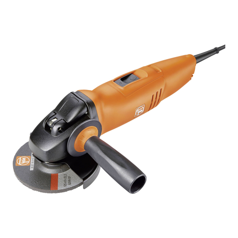
Fein WSg 20-180 Setup guide

cEignimmo
7 221 07/1111SG 20-180
7 221 08/WSG 20-230
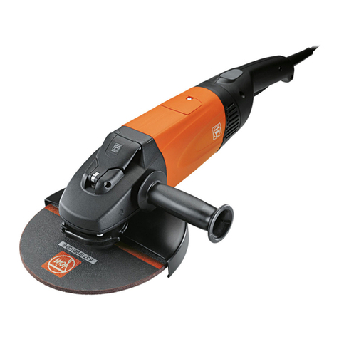
Winkelschleifer
Angle Grinder
Meuleuse d'angle
Technische Änderungen vorbehalten/Subject to technical modifications/Caractdristiques techniques sous reserve de modifications.
Reparaturanleitung
Repair Instructions
Instructions de röparation
1 88 50 315 06 1 X 08.01 Printed in Germany - Imprimd en Allemagne, FEIN Stuttgart

7 221 07/WSG 20-180/7 221 08/WSG 20-230
DE
1.
Technische Daten
Störungssuche
siehe Seite 8.
3.2
Bestellnummer
7 221 07
7 221 08
3.3
Große Funktionsprüfung
siehe Seite 6 und 7.
Bauart
WSG 20-180
WSG 20-230
Leerlaufdrehzahl
8500/min
6600/min.
Nennaufnahme
2000 W
2000 W
Leistungsabgabe
1250W
1250W
4. Demontage
des Schleifers
Stromart
1
1
Gewicht
4,5 kg
4,5 kg
•
Netzstecker ziehen!
Schutzklasse
II
g
II
E
Schleifscheibe:
4.1
Schutzhaube
max. Durchmesser
180 mm
230 mm
4.1.1
Aufgespanntes Werkzeug abnehmen.
Schleifscheibendicke
1-10 mm
1-10 mm
4.1.2
Spannhebel der Schutzhaube (780) lösen und auf der
Elastischer Schleifteller 0
180 mm
230 mm
Lagerplatte (320) drehen und abnehmen.
zulässige Umfangs-
geschwindigkeit
80 m/sec
80 m/sec
4.2
Lagerplatte
Aufnahmebohrung
22,23
22,23
4.2.1
Schrauben (540) lösen und Lagerplatte (320) abnehmen.
4.2.2
Ausgleichscheiben (520) ggf. entnehmen.
4.2.3
Welle (380) abpressen. Sonderwerkzeug
6 41 01 026 00 1 zur Auflage der Lagerplatte (320)
2.
Wartung
und Sonderwerkzeug 6 41 14 029 00 8 verwenden.
4.2.4
Schrauben (370) lösen und Abschlussplatte (360) ab-
Bitte beachten Sie, dass Elektrowerkzeuge grundsätzlich nur
nehmen.
durch Elektrofachkräfte repariert, gewartet und geprüft werden
dürfen, da durch unsachgemäße Reparaturen erhebliche
4.2.5
Kugellager (350), Abdeckscheibe (340) und Filzring
Gefährdungen für den Benutzer entstehen können (BGV A2).
(330) entnehmen.
Wiederholungsprüfungen sind nach DIN VDE 0702-1 durch-
4.3
zuführen. Nach Reparaturen sind die Vorschriften nach
Motor
DIN VDE 0701 Teil 1 / 09.00 zu beachten (Information zur
4.3.1
Schrauben (40) lösen. Deckel (80, 90) abnehmen,
Instandsetzung 5019/137 vom 09.01.1996 beachten).
Kohlebürste (30) entfernen.
Nur Original FEIN-Ersatzteile verwenden!
4.3.2
Schrauben (760, 770) lösen, Getriebegehäuse (300)
Sicherheitshinweise 3 41 30 054 06 1 durchlesen!
mit Anker (660) aus Motorgehäuse herausziehen.
Bei Inbetriebsetzung, beim Arbeiten und bei der Wartung der
4.3.3
Luftleitring (160) entnehmen.
Maschine sind die einschlägigen Unfallverhütungsvorschriften
der Berufsgenossenschaften zu beachten.
Für die bestimmungsgemäße Verwendung gilt das Gesetz über
4.3.4
Schrauben (370) lösen. Anker (660) aus Getriebe-
gehäuse (300) herausziehen.
technische Arbeitsmittel (Gerätesicherheitsgesetz).
4.3.5
Kegeltrieb (710) mit Abziehvorrichtung
6 41 02 070 00 9 und Rohr 6 41 01 002 00 4
abziehen.
4.3.6
Kugellager (700,750) abziehen.
3.
Elektrische
Funktionsprüfung
4.3.7
Halteplatte (670) mit Filzring (680) und Abdeck-
scheibe (690) abnehmen.
3.1
Kleine Funktionsprüfung
4.3.8
Schrauben (1010) lösen, Handgriff-Oberteil (1000),
3.1.1
Prüfung der Selbstanlaufsperre
•
Schleifer im eingeschalteten Zustand ans Netz an-
Verriegelungstaste (990) mit Druckfeder (980) ab-
nehmen.
schließen.
4.3.9
Stecker (840) vom Schalter abziehen.
Schleifer darf nicht anlaufen —
ansonsten ist die
Anschlusslitzen vom Schalter (910) lösen, Schalter
Elektronik defekt!
(910), Kabel (930) und Schutzschlauch entfernen.
•
Schleifer aus- und wieder einschalten.
Schleifer muss anlaufen.
3.1.2
•
Leerlaufdrehzahl
prüfen.
Die Drehzahl ist über die Elektronik eingestellt.
WSG 20-180: 7500/min., WSG 20-230: 5900/min.
2
1 88 50 315 06
1 X 08.01

Deckel (80/90) einsetzen und verschrauben.
Elektronik (140) aufstecken, Lage beachten, auf
Druckpolster (820) achten.
Bei Bedarf Druckpolster (820, 130) austauschen.
Modulgehäuse (110) aufsetzen und verschrauben.
Schalter (910) anschließen, Anschlussplan Seite 5
beachten.
Handgriff-Unterteil (900) auf Modulgehäuse (110)
aufsetzen.
Schalter (910) mit Kabel (930) und Schutzschlauch
(920) einsetzen.
Verriegelungstaste (990) mit Druckfeder (980)
einsetzen.
Handgriff-Oberteil (1000) aufsetzen. Schrauben (1010)
einsetzen.
Achtung:
Zuerst Schrauben kabelseitig anziehen,
danach Schrauben motorseitig anziehen.
Lagerplatte
Filzring (330) und Abdeckscheibe (340) in Lagerplatte
(320) einlegen.
Kugellager (350) einpressen.
Abschlussplatte (360) einlegen und mit Schrauben
(370) verschrauben.
Ring (430) einsetzen und Kegelrad (440) aufpressen.
Dabei Rohr 6 41 01 025 00 8 für Tellerrad
verwenden.
Komplette Lagerplatte in Getriebegehäuse (300)
einsetzen und verschrauben.
Flankenspiel prüfen.
Ggf. mit Ausgleichscheiben (520) einjustieren.
Probelauf durchführen.
Lagerplatte abnehmen und 70 g Getriebefett
0 40 101 0100 4 einfüllen, Lagerplatte montieren.
Schutzhaube (780) montieren.
Handgriff (790) eindrehen. Flansche (800, 810)
montieren.
Funktionsprüfung, Probelauf und Sicherheits-
prüfung durchführen.
5.2.7
5.2.8
5.2.9
5.2.10
5.2.11
5.2.12
5.2.13
5.2.14
5.2.15
5.3
5.3.1
5.3.2
5.3.3
5.3.4
5.3.5
5.3.6
5.3.7
5.3.8
5.3.9
5.3.10
5.3.11
4.5
4.5.1
4.3.10
4.3.11
4.3.12
4.3.13
4.4
4.4.1
5.1
5.1.1
5.1.2
5.1.3
5.1.4
5.2
5.2.1
5.2.2
5.2.3
5.2.4
5.2.5
5.2.6
7 221 07/WSG 20-180/7 221 08/WSG 20-230
DE
Handgriff-Unterteil (900) abnehmen.
Schrauben (1010) lösen. Modulgehäuse (110) mit
Elektronik (140) abnehmen.
Grundplatte (120) abziehen.
Schrauben (70) lösen und Polpaket (60) demontieren.
Getriebegehäuse
Bei Bedarf Arretierbolzen (570) mit Durchschlag aus
Druckknopf (600) herausdrücken. Druckknopf wird
dabei zerstört und muss ersetzt werden.
Schalter
Bei Bedarf Einschaltsperre abnehmen, dazu Bolzen
entfernen. Auf Druckfeder achten! Kontaktplatte
(955) austauschen. Bolzen und Einschaltsperre
montieren.
5. Montage des Schleifers
Anker
Halteplatte (670) mit Filzring (680) und Abdeck-
scheibe (690) auf Ankerwelle auflegen.
Kugellager (700) aufpressen.
Kegeltrieb (710) erwärmen (ca. 100°C) und mit
Aufpressvorrichtung 6 41 01 024 00 4 aufpressen.
Kollektorseitiges Kugellager (750) aufpressen.
Getriebegehäuse und Motorgehäuse
Nadelhülse (310) bis zum Anschlag einpressen.
Bei Bedarf Arretierbolzen (570) mit aufgelegtem
Dichtungsring (580) durch Getriebegehäuse durch-
stecken, Feder (590) auflegen und neuen Druckknopf
(690) aufpressen.
Gummibuchse (650) in Getriebegehäuse (300)
einlegen.
Vormontierten Anker (660) in Getriebegehäuse (300)
einsetzen und verschrauben.
Auf Sicherungsscheibe (720) achten. Vorrichtung
6 41 01 020 00 0 verwenden.
Gummibuchse (740) und Polpaket (60) in Motorge-
häuse (10) einsetzen. Einbaulage beachten (siehe
Abb. Seite 9). Polpaket (60) verschrauben.
Grundplatte (120) aufstecken und mit Stecker von
Polpaket in Motorgehäuse einsetzen und arretieren.
Polpaketanschlusslitzen an Kohlehalter anschließen
und in die Nut der Kohlehalterplatte einlegen, Kohle-
halter (20) mit Kohlebürste (30) in Motorgehäuse
einsetzen und verschrauben.
Achtung: Der Kohlehalter wird mit vormontierter
Kohlebürste ausgeliefert.
Nach Einbau des neuen Kohlehalters muss die Zunge
der Spiralfeder in die Nut am Kohlehalter eingesetzt
werden. Dadurch wird die Kohlebürste frei beweglich
und liegt am Kollektor auf.
3
1 88 50 315 06 1 X 08.01
7 221 07/WSG 20-180/7 221 08/WSG 20-230
6. Sonderwerkzeuge / Special tools / Outils spöciaux
/ /
4 (76)
øS5,242
10
0
Bez.mit
4
0
'6
1
I
0
di
4010
go
r
o
d
—
1
20--
\
.t.
punktgeschweilli
r
;
1
.
\
3x120°
1
1
3
1
b
Aufpressvorrichtung
für Ankerritzel
Pressing-on device
for armature pinion
6 41 01 024 00 4
Bague exterieure
pour pignon dinduit
0245
,
4
1
2
--
////////// /
/
/ 1
/
/ / /
—
1
ii6,2'
11
0
130
0 120
—.
5
6
'kg,
8
-
0
/
2
0110
...
01'
30
2
J
Abziehplatte
für Ankerritzel
Base plate
for armature
Plaque support
pour
pinion
pignon dinduit
6 41 02 070 00 9
Rohr
zur Auflage der Abziehplatte
Pipe
for supporting the base plate
6 41 01 002 00 4
Tube
pour
appliquer la plaque mdractrice
'9)
60 +
0,2
9 (78,3)
b
4.
/
/
/
/
/
/
rn
PI
csi
rn
/
/
/
/
/
7
/
/
1x45°
0O
/ /
b
Rohr
zur Auflage der Halteplatte
Pipe
for supporting the retaining plate
6 41 01 020 00 0
Tube
pour appliquer la plaque de retenue
Rohr
zur Auflage der Lagerplatte
Pipe
for supporting the bearing plate
6 41 01 026 00 1
Tube
pour appliquer la plaque de palier
4
1 88 50 315 06 1 X 08.01
C•1
0
6. Sonderwerkzeuge / Special tools / Outils spöciaux
6
0
+
02
Rohr
zum Ein- und Auspressen der Welle
Pipe
for pressing the shatt in and out
Tube
pour enfoncer et extraire l'arbre
Druckstück
zum Auspressen der Welle
Pressing piece
for pressing out the shaft
6 41 14 029 00 8
Piece d'appui
pour extraire l'arbre
6 41 01 025 00 8
45
12
7 221 07/WSG 20-180/7 221 08/WSG 20-230
Anschlussplan
Connecting plan
Schema des connexions
Netz
Net
Rdseau
Fettmengen und Fettarten
Types and quantities of grease
Types et quantitös de graisse
Fenart
Type of grease
Type de graisse
Tuben-Inhalt
Contents of tube
Contenu de tube
Bestellnummer
Order Reference
Rdference
Fettmenge
Quantity
Quantite
0 40 101 0100
4
85
g
3 21 60
003 01 4
Getriebe/gearing/r6ducteur:
70 g
0 40 101 0100 4
85 g
3 21 60 003 01 4
Nadelhülse/needle bearing/douille ä aiguilles (310)
Rillenkugellager/grooved ball bearing/roulements ä billes (350)
1 88 50 315 06 1 X 08.01
5

langsam hochdrehen
Transformator 230 V / > 4 A (= Leerlaufstrom Motor)
Keine Selbstablaufsperre
Kein Sanftanlauf, daher Spannung
Durchgangsprüfung Motor
Bitte beachten Sie, dass Elektrowerkzeuge
grundsätzlich nur durch Elektrofachkräfte
repariert, gewartet und geprüft werden
dürfen, da durch unsachgemäße Reparatu-
ren erhebliche Gefährdungen für den
Benutzer entstehen können (BGV A2).
Motor (Ersatzmotor)
Reparatur-Set:
Adapter
Achtung:
Kontakte unter
Spannung!
ce
—
X 1.3
—
X 1.1
Handgriff mit Elektronikmodul
Anschluss Schalter
1)
01 t
-
--43)2
t eNt
1
Reparatur-Set:
Verbindungsleitung mit Stecker
für Elektronik (X1.1—X1.3)
Durchgangsprüfung
Schalter—Elektronik
Ersatzlast
1
Glühlampe
100W
7
7N
Keine Drehzahlabsenkung, daher auf max. 165 V hochdrehen
_J
1,
90
SE
05 88 l•
X
OD
Reparatur-Set:
Verbindungsleitungen
mit Flachsteckkontakten
< = 0,8 mm
OE
Z
-
OZ
DSM
/80
1.
ZZ
L/
081.
-
OZ DSA
A/L0
1ZZ
L

I.
90 SI.
E OS 88
1.
X
CO
3.3 Große Funktionsprüfung
Pridanweisung
Vermeiden Sie bei der Fehlersuche unnötige
Trennungen von Steckverbindui igen.
•
Handgriff aufschrauben, Handgriff-Hälften ent-
fernen.
•
Modulgehäuse vom Motorgehäuse trennen, ohne
die Verbindung Schalter — Modulgehäuse zu lösen.
•
Bei allen Prüfungen an Spannung ist der Handgriff
wieder zu schließen.
In diesem Zustand lassen sich alle elektrischen
Funktionen prüfen!
Die Federkontakte in den Steckern dürfen max.
0,8 mm geweitet werden. Verwenden Sie deshalb
unbedingt das angebotene Reparatur-Set, Bestell-
nummer 6 41 32 009 00 9.
3.3.1
Prüfung Motor (ohne Elektronik)
3.3.1.1
Durchgangsprüfung ohne Spannung
über das
3-polige
Steckergehäuse.
Verbindungsleitungen mit Flachsteck-
kontakten aus Reparatur-Set verwenden.
•
Motor gesamt
1D— 2D:
BK — BK
3.3.1.2
Funktionsprüfung mit Spannung
über das
3-polige
Steckergehäuse.
Adapter aus Reparatur-Set ver-
wenden. Prüfspannung über Trafo oder funktionie-
rende Einheit Handgriff-Elektronikmodul.
Achtung:
Bei Trafobetrieb keine Selbstanlauf-
sperre, kein Sanftanlauf, keine Drehzahl-
begrenzung!
Trafospannung daher langsam von 0 V
auf max. 165V hochdrehen!
WSG 20-180:
ca. 7500/min.
WSG 20-230:
ca. 5900/min.
3.3.2
Prüfung Schalter und Verbindungsleitungen zur
Elektronik
3.3.2.1
Sichtprüfung
•
Schraubanschluss N t
•
Steckanschluss Si t
•
Leitungen auf Beschädigung prüfen.
3.3.2.2
Durchgangsprüfung ohne Spannung
über die
Steck-
kontakte (X) der Elektronik
und
Schalteranschlüsse (S).
Schalter in Stellung
"EIN"
•
X 1.1 — S 2 t
3.3.3
Prüfung Elektronik
Funktionsprüfung mit Spannung
über die
Steckkontakte der Elektronik.
Aus Sicher-
heitsgründen ist der Handgriff zu schließen.
Achtung: Die Steckkontakte der Elektronik
sind berührbar und stehen unter
Spannung!
Verbindungsleitung mit 3-poligem Stecker
aus Reparatur-Set verwenden.
3.3.3.1
Anlauf und Regelverhalten
•
Glühlampe 100 W an X 1.1 — X 1.3
anschließen, evtl. Spannung messen.
•
Prüfeinheit Handgriff-Elektronikmodul
an Netz stecken, Schalter einschalten.
—>
Lastspannung steigt langsam an, Endwert
ca. 125 V, bzw. Lampe leuchtet. (Die
Prüfung ist auch mit anderen Glüh-
lannpen > 25 W möglich, die Last-
spannung nimmt dann andere Werte an).
3.3.3.2
Selbstanlaufsperre
Im Anschluss an 3.3.3.1 Netzstecker
ziehen (bei Schalter "EIN") und wieder
stecken.
--> Lastspannung < 1V, bzw. Lampe bleibt
dunkel.
OEZ
-
OZ
DSM/8
0 ZZ
L/08
1.
-
Ot
DSM/L
O 1.
ZZ
L

7 221 07/WSG 20-180/7 221 08/WSG 20-230
3.2 Störungssuche
Störung
Mögliche Ursachen
Prüfmöglichkeiten:
3.2.1
3.2.2
3.2.3
3.2.4
Motor läuft nicht an.
Unterbrechung Netzkabel
oder Steckverbindungen.
Motorschalter defekt.
Kohlebürsten abgelaufen.
Motor defekt.
Elektronik defekt.
3.3.1.1
3.3.2
3.3.2
Sichtkontrolle.
3.3.1
3.3.3
Motor schaltet
"ohne Grund" ab.
Wackelkontakt
(kann zum Ansprechen der
Selbstanlaufsperre führen).
Elektronik defekt.
3.3.1.1
3.3.2
Netzkabel.
3.3.3
Drehzahl schwankt
oder
Maschine zu schwach, kein
Regelverhalten spürbar.
Elektronik defekt.
zusätzliche mechanische Be-
lastung (Getriebe, Lager,
Vibrationen, ...).
Kollektor, Kohlebürsten defekt.
3.3.3
Prüfen.
Leerlaufstrom
messen.
Sichtkontrolle.
Motor läuft an, wenn die einge-
schaltete Maschine an das Netz
gesteckt wird.
Elektronik defekt.
Keine weitere Prüfung erforderlich.
DE
A
8
1 88 50 315 06 1 X 08.01
Schnitt
Section A-A
Coupe
Handgriffverschraubung in
Reihenfolge a, b, c, d
durchführen.
Screws of handle in
following sequence a,b,c,d.
Les vis de la poigne
rnonte en sens a,b,c,d.
C-C
O
EZ
-
OZ
DSM/
80 l•
ZZ L.
1
081,
-
O
7
DSM/Z0
l•
ZZ
L
Co

Führung der Litzen in Nut des Bürstenhalters beachten
Observe guide of brush shunts in groove of brush holder
Respecter le guidage des torons dans la rainure du porte-balai
Einzelheit
Details Z
Details
mit Loctite Nr. 573 abgedichtet
sealed with "Loctite No. 573"
rendu etanche avec «Loctite No. 573»
Lage Elektronik beachten
Ensure that the electronics module is correctly positioned
Attention ä la position de l'electrontque
Lage der Rippe beachten!
Observe position!
Respectez la position!
warm aufgepresst (80°-100 C°)
warm press fit (80°-100 C°)
enfonc6 ä chaud (80°400 C°)
7 221 07/WSG 20-180/7 221 08/WSG 20-230
Lage Stecker/Polpaket beachten
Observe the position of plug/pole housing
Respecter la position du connecteur/stator
Einzelheit
Details Y
Details
10
1 88 50 315 06 1 X 08.01
Description
pressure button
rubber sleeve
armature with winding, compl.,110 V
armature with winding, compl.,120 V
armature with winding, compl.,
220-240 V
retaining plate
felt ring
cover plate
grooved ball bearing
securing disc
rubber sleeve
grooved ball bearing
screw "Ejot-PT"
screw "Ejot-PT"
bolster
connection cable
lower handle section
ON/Off switch, ass.
ON/Off switch, ass.
(dead man design)
oval head screw
protecting sleeve
cable, ass. (220-240 V)
cable, ass. (110V, GB)
cable, ass. (240 V, AU)
cable, ass. (230 V, CH)
cable, ass. (120V, 60 Hz
US, CA)
cable clamping piece
screw "Ejot-PT"
contact plate
oval head screw
pressure spring
locking button
upper handle section
screw "Ejot-PT"
Accessories as listed
safety guard, ass., WSG 20-180
safety guard, ass., WSG 20-230
side handle
grinding wheel flange
grinding wheel flange, US, CA
grinding wheel flange, M 14
grinding wheel flange,
5/8-11 UNC, US, CA
single ended two-slot nut driver
Teil-Nr.
Part.No.
No.
Bestellnummer
Order Reference
Reference
Benennung
600
3
28 05
180 004
1
Druckknopf
650
3
05 07
169 007
1
Gummibüchse
660
5
3 275
002 11
8
1
Anker kpl. mit Wicklung, 110 V
660
53 275
002 12
4
1
Anker kpl. mit Wicklung, 120 V
660
5
3 275
002 23
4
1
Anker kpl. mit Wicklung,
220-240 V
670
3
24 16
106 00
1
1
Halteplatte
680
3
06 01
050 00
2
1
Filzring
690
3
24 11
083 00
1 1
Abdeckscheibe
700
4
17 01
213 09
6
1
Rillenkugellager
720
4
24 43
003 04
3
2
Sicherungsschelbe
740
3
05 07
168 00
3
1
Gummibüchse
750
4
17 01
207 03
3
1
Rillenkugellager
760
4
30 70
029 00
2
2
Ejot-PT-Schraube
770
4
30 70
030 00
4
2
Ejot-PT-Schraube
820
3
14 15
089 00
9
1
Druckpolster
840
3
07 19
595 01
3
1
Verbindungskabel
900
312 04
167 00
0
1
Handgriff-Unterteil
910
3
07 01
245 01
4
1
zus.ges. Ausschalter
3
07 01
247 011
1
zus.ges. Ausschalter
(Totmannausführung)
915
4
30 41
001 99
4
2
Linsenschraube
920
3
14 13
094 00
7
1
Schutzschlauch
930
3
07 07
387 01
2
1
zus.ges. Kabel (220-240 V)
932
3
07 07
391 01
5
1
zus.ges. Kabel (110V, GB)
933
3
07 07
393 01
2
1
zus.ges. Kabel (240 V, AU)
934
3
07 07
394 01
0
1
zus.ges. Kabel (230 V, CH)
935
3
07 07
398 01
9
1
zus.ges. Kabel (120 V, 60 Hz
US, CA)
940
3
24 31
042 00
8
1
Kabelklemmstück
950
4
30 70
035 00
2
1
Ejot-PT-Schraube
955
3
07 17
203 01
4
1
Kontaktplatte
960
4
30 41
016 04
2
2
Linsenschraube
980
3
09 01
343 00
7
1
Druckfeder
990
3
28 16
057 007
1
Verriegelungstaste
1000
3
12 04
168 00
8
Handgriff-Oberteil
1010
4
30 70
031 00
3
8
Ejot-PT-Schraube
Listenmäßiges Zubehör
780
3
18 10
245 01
2
z.g. Schutzhaube, WSG 20-180
3
18 10
246 01
5
z.g. Schutzhaube, WSG 20-230
790
3
21 19
032 00
2
seitlicher Handgriff
800
6
38 01
120 00
6
Schleifscheibenflansch
6
38 01
095 00
8
Schleifscheibenflansch, US, CA
810
6
38 02
052 00
0
Schleifscheibenflansch, M 14
6
38 02
098 00
7
Schleifscheibenflansch,
5/8-11 UNC, US, CA
6
29 10
022 00
2
Zweilochmutterndreher
Designation
bouton ä pression
douille en caoutchouc
induit bobine, compl., 110 V
induit bobine, compl., 120 V
induit bobine, compl.,
220-240 V
plaque de retenue
bague en feutre
rondelle de recouvrement
roulement ä billes rainure
rondelle de securite
douille en caoutchouc
roulement ä billes rainurd
vis "Ejot-PT"
vis "Ejot-PT"
fourrure
cäble de raccordement
partie inferieure de la poignee
ens. interrupteur
ens. interrupteur
(version homme mort)
vis ä tete bombe
gaine protectrice
ens. cäble (220-240 V)
ens. cäble (110V, GB)
ens. cäble (240 V, AU)
ens. cäble (230 V, CH)
ens. cäble (120V, 60 Hz
US, CA)
serre-cäble
vis "Ejot-PT"
plaque de contact
vis ä tete bomb&
ressort ä pression
touche de verrouillage
partie superieure de la poignee
vis "Ejot-PT"
Accessoires suivant liste
ens. capot protecteur, WSG 20-180
ens. capot protecteur, WSG 20-230
poignee laterale
flasque de meule
flasque de meule, US, CA
flasque de meule, M 14
flasque de meule,
5/8-11 UNC, US, CA
cl
e ä ergots
Description
motor housing
brush holder, ass., 220-240 V
brush holder, ass., 110-120V
carbon brush, 220-240 V
carbon brush, 110-120V
screw "Ejot-PT"
pole housing with winding, 110V
pole housing with winding, 120V
pole housing with winding,
220-240 V
remform screw
upper cover
lower cover
module housing base plate
base plate
bolster
electronics module (110V)
electronics module (120V)
electronics module (220 V 60 Hz)
electronics module (230 V)
electronics module (240 V)
air conducting ring
gear housing
needle bearing
bearing plate, WSG 20-180
bearing plate, WSG 20-230
felt ring
collar
grooved ball bearing
cover plate
oval head screw
driving shaft (M 14)
driving shaft (5/8"-11 UNC,
US, CA)
ring
bevel gear, ass., 15/52 teeth
WSG 20-180
bevel gear, ass., 12/53 teeth
WSG 20-230
washer
securing disc
oval head screw
sleeve
retention button
sealing ring
pressure spring
Designation
carter moteur
ens. porte-balais, 220-240 V
ens. porte-balais, 110-120V
balais-charbon, 220-240 V
balais-charbon, 110-120V
vis "Ejot-PT"
stator bobind, 110 V
stator bobine, 120V
stator bobine,
220-240 V
vis Remform
couvercle
couvercle
boitier du module
embase
fourrure
commande dlectronique (110 V)
commande electronique (120 V)
commande electronique (220 V
60 Hz)
commande electronique (230 V)
commande electronique (240 V)
anneau de guidage de l'air
carter de reducteur
roulement ä aiguilles
plaque d'appui, WSG 20-180
plaque d'appui, WSG 20-230
bague en feutre
rondelle de recouvrement
roulement ä billes rainure
plaque de fermeture
vis ä tete bombe
arbre d'entrainement (M 14)
arbre d'entrainement (5/8"-11 UNC,
US, CA)
bague
ens. reducteur ä pignons, 15/52 dents
WSG 20-180
ens. reducteur ä pignons, 12/53 dents
WSG 20-230
disque d'equilibrage
rondelle de securite
vis ä tete bomb&
douille
boulon
bague de securite
ressort ä pression
7 221 07/WSG 20-180/7 221 08/WSG 20-230
Einzelteile
Component Parts Piöces dötachöes
Einzelteile
Component Parts
Piöces dötachöes
Teil-Nr.
Part.No.
No.
Bestellnummer
Order Reference
Reference
Benennung
10
3 19 03
214
006
1
Motorgehäuse
20
3 07 12
090
01 9
2
z.g. Bürstenhalter, 220-240 V
3 07 12
090
031
2
z.g. Bürstenhalter, 110-120V
30
3 07 11
137
00 6
2
Kohlebürste, 220-240 V
3 07 11
143
006
2
Kohlebürste, 110-120V
40
4 30 70
027
00 0
4
Ejot-PT-Schraube
60
51 275
003
11 0
1
Polpaket mit Wicklung, 110V
51 275
003
126
1
Polpaket mit Wicklung, 120 V
5 1 275
003
23 6
1
Polpaket mit Wicklung,
220-240 V
70
4 30 72
011
008
2
Remform-Schraube
3 24 2/
117
00 8
1
Deckel, oben
90
3 24 27
118
00 6
1
Deckel, unten
110
3 12 07
251
008
Modulgehäuse
120
3 14 28
144
00 5
2
Grundplatte
130
3 14 15
092
00 3
1
Druckpolster
140
3 07 62
253
99 7
1
Elektronik (110V)
3 07 62
254
99 5
1
Elektronik (120 V)
3 07 62
357
99 2
1
Elektronik (220 V 60 Hz)
3 07 62
251
99 0
Elektronik (230 V)
3 07 62
256
99 2
Elektronik (240 V)
160
3 14 28
141
000
Luftleitring
300
3 12 06
114
03 1
1
Getriebegehäuse
310
4 17 06
030
00 7
1
Nadellager
320
3 24 19
122
00 9
1
Lagerplatte, WSG 20-180
3 24 19
123
00 3
1
Lagerplatte, WSG 20-230
330
3 06 01
110
00 5
1
Filzring
340
3 24 11
084
00 9
1
Abdeckscheibe
350
4 17 01
224
02 4
1
Rillenkugellager
360
3 24 16
105
00 8
1
Abschlussplatte
370
4 30 64
002
04 3
5
Linsenschraube
380
334 06
289
00 2
1
Antriebswelle (M 14)
334 06
291
00 3
1
Antriebswelle (5/8"-11 UNC,
US, CA)
430
3 26 01
273
00 6
1
Ring
445
338 09
232
01 6
Kegelradgetriebe, 15/52 Zähne
WSG 20-180
338 09
233
01 0
1
Kegelradgetriebe, 12/53 Zähne
WSG 20-230
520
1)
3 26 24
118
02 2
Ausgleichscheibe
530
4 24 43
004
05 7
4
Sicherungsscheibe
540
4 30 64
009
05 4
4
Linsenschraube
560
3 05 07
230
00 9
1
Buchse
570
3 02 17
335
00 5
1
Arretierbolzen
580
4 06 12
137
00 8
1
Runddichtring
590
3 09 01
354
00 4
1
Druckfeder
1)
Anzahl nach Bedarf/Quantity as needed/Quantite suivant les besoins
1)
Anzahl nach Bedarf/Quantity as needed/Quantitd suivant les besoins
14
11
1 88 50 315 06 1 X 08.01

Teil-Nr. Bestellnummer
Part.No. Order Reference
No.
Reference
319 03 214 006
1
3 07 12 090 01 9 220-240V)
3 07 12 090 03 1 110-120
3 07 11 137 00 6 220-240V
3 07 11 143 00 6 110-120V
4 30 70 027 00 0
5 1 275 003 11 0 110V
5 1 275 003 12 6 120V
5 1 275 003 23 6 220 240V)
4 30 72 011 00 8
3 24 27 117 00 8
3 24 27 118 00 6
3 12 07 251 008
314 28 144 00 5
3 14 15 092 00 3
3 07 62 253 99 7
3 07 62 254 99 5
3 07 62 357 99 2
3 07 62 251 99 0
3 07 62 256 99 2
3 14 28 141 000
110V
120 V)
220 V 60 Hz)
230 V)
240 V)
3 12 06 114 03 1
4 17 06 030 007
3 24 19 122 00 9 (WSG 20-180)
3 24 19 123 003 (WSG 20-230)
3 06 01 110 00 5
3 24 11 084 00 9
4 17 01 224 02 4
3 24 16 105 00 8
4 30 64 002 04 3
3 34 06 289 00 2 (M 14)
3 34 06 291 00 3(5/8-11 UNC,
US,CA)
3 26 01 273 00 6
3 38 09 232 01 6 (Z = 15/52)
(WSG 20-180)
3 38 09 233 01 0 (Z = 12/53)
(WSG 20-230)
3 26 24 118 02 2
4 24 43 004 05 7
4 30 64 009 05 4
3 05 07 230 00 9
3 02 17 335 00 5
406 12 137 008
3 09 01 354 00 4
3 28 05 180 004
3 05 07 169 007
5 3 275 002 11 8 110V
5 3 275 002 12 4 120V
5 3 275 002 23 4 220-240 V)
3 24 16 106 00 1
3 06 01 050 00 2
3 24 11 083 00 1
4 17 01 213 09 6
4 24 43 003 04 3
3 05 07 168 00 3
4 17 01 207 03 3
4 30 70 029 00 2
4 30 70 030 00 4
318 10 245 01 2 (WSG 20-180)
318 10 246 01 5 (WSG 20-230)
3 21 19 032 00 2
6 38 01 120 00 6
6 38 01 095 00 8 t.JS CA)
6 38 02 052 00 0 M4)
6 38 02 098 00 7 5/8-11 UNC,
US, CA)
3 14 15 089 00 9
3 07 19 595 01 3
312 04 167 00 0
3 07 01 245 01 4
3 07 01 247 011 (Totmannausf.)
3 14 13 094 00 7
3 07 07 387 01 2
3 07 07 391 01 5
3 07 07 393 01 2
3 07 07 394 01 0
3 07 07 398 01 9
3 24 31 042 008
4 30 70 035 00 2
3 07 17 203 01 4
4 30 41 016 04 2
3 09 01 343 00 7
3 28 16 057 00 7
312 04 168 00 8
4 30 70 031 00 3
220-240 V
110V, GB
240 V, ALM
230V, CH
120V, CA,US)
10
20
30
40
60
70
80
90
110
120
130
140
160
300
310
320
330
340
350
360
370
380
430
445
520
1)
530
540
560
570
580
590
600
650
660
670
680
690
700
720
740
750
760
770
780
790
800
810
820
840
900
910
915
920
930
932
933
934
935
940
950
955
960
980
990
1000
1010
1
2
2
2
2
4
2
1
2
1
1
1
1
1
1
1
1
5
1
1
4
1
2
2
2
1
2
2
1
8
770
120
660
934
932
933
ee
tz
„obA
V.'
710
440
370
340
330
520
30
40<
20'
10
90
160
740
750
70
680
690
700
900
840
130
820
140
930
920
940950
960
915
2
N 08/ CH
N 13/US
N 06/ AU
N
24/ GB
1)
Anza
h
l nac
h
Be
da
r
f/Quan
t
ity
as
nee
de
d/Qu
an
t
it
e su
iva
n
t
les
beso
ins
790
CY\
60
430
360
350
7 221 07/WSG 20-180/7 221 08/WSG 20-230
12
1 88 50 315 06 1 X 08.01
13

7 221 07/WSG 20-180/7 221 08/WSG 20-230
EN
1.
Technical Data
Troubleshooting
see page 17.
Comprehensive function test
see pages 18 and 19.
3.2
Order Reference
7 221 07
7 221 08
Type
WSG 20-180
WSG 20-230
Speed, no load
8500/min
6600/min.
Input
2000W
2000W
Output
1250 W
1250W
Current type
1
1 -
Weight
4.5 kg
4.5 kg
Safety Class
II
g
II EI
Grinding wheel:
Max. diameter
180 mm
230 mm
Max. width
1-10 mm
1-10 mm
Sanding disc 0
180 mm
230 mm
Max. permissible peripheral
speed
80 m/sec
80 m/sec
Diameter of mounting hole
22.23
22.23
3.3
4. Disassembling
the grinder
4.1
4.1.1
4.1.2
•
Remove the power plug from the mains receptacle!
Safety guard
Remove the mounted tool.
Loosen the clamping lever on the safety guard (780)
and rotate on the bearing plate (320) and remove.
Bearing plate
Remove the screws (540) and bearing plate (320).
If required, remove the washers (520).
Force off the shaft (380). Use special tool
6 41 01 026 00 1 for mounting the bearing plate
(320) and special tool 6 41 14 029 00 8.
Remove the screws (370) and cover plate (360).
Remove the ball bearing (350), collar (340) and felt
ring (330).
Motor
Remove the screws (40) and cover (80, 90) and take
out the carbon brush (30).
Remove the screws (760, 770) and pull the gear
housing (300) and armature (660) out of the motor
housing.
Remove the air conducting ring (160).
Remove the screws (370). Pull the armature (660)
out of the gear housing (300).
Remove the bevel gear (710) using extracting device
6 41 02 070 00 9 and pipe 6 41 01 002 00 4.
Remove the ball bearings (700, 750).
Remove the retaining plate (670) together with felt
ring (680) and cover plate (690).
Remove the screws (1010) and upper handle section
(1000) and locking button (990) together with
pressure spring (980).
Remove connection cable (840) from the switch.
Disconnect the brush shunts from the switch (910)
and remove the switch (910), cable (930) and
protecting sleeve.
Remove the lower handle section (900).
Remove the screws (1010) and module housing (110)
together with electronics module (140).
Remove the base plate (120).
Remove the screws (70) and pole housing (60).
4.2
4.2.1
4.2.2
4.2.3
4.2.4
4.2.5
2.
Maintenance
Please note tiat as a basic rule, power tools should only be
repaired, serviced and checked by qualified electricians, since
repairs carried out improperly can be a serious hazard for the
user (BGVA2).
Check tests have to be carried out according to DIN VDE 0702-1.
After repair the regulations laid down in the German Industrial
Standard DIN VDE 0701 Part 1 /9.00 must be connplied with.
See special information booklet (No. 5019/137, 09.01.1996)
on repair work.
Only use original FEIN spare parts! Please read safety
instructions No. 3 41 30 054 06 1 thoroughly!
The relevant German Industrial Insurers' accident prevention
regulations or equivalent must be complied with when starting
up, using and servicing the power tool.
Correct usage of technical tools is as stipulated by the German
Technical EqLipment Safety Act.
4.3
4.3.1
4.3.2
4.3.3
4.3.4
4.3.5
4.3.6
4.3.7
4.3.8
4.3.9
4.3.10
4.3.11
4.3.12
4.3.13
3.
Electrical
Function Test
3.1
3.1.1
3.1.2
Small function test
Safely interlock check
•
With its power switch in the ON position, connect
the grinder to the mains.
Grinder should not start -
However, if it does, the
electronics assembly is defective!
•
Switch grinder OFF, and ON again.
Grinder must statt now.
Check the
no load speed.
The speed has been set via the electronics module.
WSG 20-180: 7500/min., WSG 20-230: 5900/min.
1 88 50 315 06 1 X 08.01
15

Insert and screw on the cover (80/90).
Attach the electronics module (140), ensure that the
slot is correctly positioned and pay attention to
bolster (820).
If required, replace the bolster (820, 130).
Attach and screw on the module housing (110).
Connect the switch (910). Observe the connecting
plan on page 5.
Attach the lower handle section (900) to the module
housing (110).
Insert the switch (910) together with cable (930) and
protecting sleeve (920).
Insert the locking button (990) together with
pressure spring (980).
Attach the upper handle section (1000). Insert the
screws (1010).
Waming! Tighten the screws on the cable side first,
then tighten the screws on the motor side.
Bearing plate
Insert the felt ring (330) and collar (340) in the
bearing plate (320).
Press in the ball bearing (350).
Insert the cover plate (360) and attach using screws
(370).
Insert ring (430) and press on the bevel gear (440).
In
so doing, use supporting tube 6 41 01 025 00 8.
Insert the complete bearing plate into the gear
housing (300) and screw together.
Check gear backlash.
If required, adjust backlash by adding/removing
washers (520).
Perform a test run.
Remove the bearing plate and fill with 70 g of gear
grease 0 40 101 0100 4. Attach the bearing plate.
Attach the safety guard (780).
Screw in handle (790). Assemble flange (800, 810).
Perform a function test, test run and safety check.
5.2.7
5.2.8
5.2.9
5.2.10
5.2.11
5.2.12
5.2.13
5.2.14
5.2.15
5.3
5.3.1
5.3.2
5.3.3
5.3.4
5.3.5
5.3.6
5.3.7
5.3.8
5.3.9
5.3.10
5.3.11
4.4
4.4.1
4.5
4.5.1
5.2
5.2.1
5.2.2
5.2.3
5.2.4
5.2.5
5.2.6
7 221 07/WSG 20-180/7 221 08/WSG 20-230
EN
Gear housing
If required, press out the retention button (570) with
force out of press button (600). Press button
becomes damaged during the process and must be
replaced.
Switch
If required, remove the lock off. To do this, remove
the locking bolt. Beware of pressure spring! Replace
contact plate (955). Fit pin and lock off.
5. Assembling the grinder
Armature
Place the retaining plate (670) together with felt ring
(680) and cover plate (690) on the armature shaft.
Press on the ball bearing (700).
Warm up the bevel gear (710) (to approx. 100 °C)
and press on with the pressing-on device
6 41 01 024 00 4.
Press on the ball bearing (750) on the commutator
side.
Gear housing and motor housing
Press in the needle bearing (310) as far as it will go.
If necessary, press the retention button (570) with
sealing ring (580) placed on, through the gear
housing, place the spring (590) on and press on a
new press button (690).
Insert the rubber sleeve (650) into the gear housing
(300).
Insert the pre-assernbled armature (660) into the gear
housing (300) and screw together.
Pay attention to lock washer (720).
Use device 6 41 01 020 00 0.
Insert the rubber sleeve (740) and pole housing (60)
in the motor housing (10). Pay attention to the
inserting position (see Fig. page 9). Screw on the pole
housing (60).
Attach the base plate (120) and together with the
plug of the pole housing insert into the motor
housing and secure.
Connect pole housing brush shunts to the carbon
holder and position in the groove.
Insert the brush holder (20) together with the carbon
brush (30) into the motor housing and screw
together.
Note:
The brush holder is supplied with a pre-
assembled carbon brush.
After installing the new brush holder, insert the guide
of the coiled spring into the groove in the brush
holder. The carbon brush can now move freely and is
positioned on the commutator.
16
1 88 50 315 06 1 X 08.01
7 221 07/WSG 20-180/7 221 08/WSG 20-230
3.2 Troubleshooting
Problem
Possible cause
Test options:
3.2.1
3.2.2
3.2.3
3.2.4
Motor does not start.
Interruption in mains cable or
3.3.1.1
plug-and-socket connections.
3.3.2
Motor switch defective.
3.3.2
Carbon brushes worn.
Visual inspection.
Motor defective.
3.3.1
Electronics module defective.
3.3.3
Motor switches "OFF" for no
apparent reason.
Loose contact (may trigger
3.3.1.1
the safety interlock).
3.3.2
Mains cable.
Electronics module defective.
3.3.3
Speed tuctuates
1
Electronics module defective.
3.3.3
or
power tool too weak, no control
Additional mechanical load
' Test.
response noticeable.
,
(gears, bearings, vibrations, etc).
Measure no-load current.
Commutator, carbon brushes
, Visual inspection.
defective.
I
Motor starts when power tool
Electronics module defective.
1
No further test required.
with switch in "ON" position is
1
I
connected to the mains.
1
EN
1 88 50 315 06 1 X 08.01
17

7
7•
—
X 1.3
—
X 1.1
Handle with electronics module
Continuity test switch electronics
module
Repair set:
•
011'
,.0
Connection cable with plug for
11)
-
--2)2 t eNT
electronics module (X1.1—X1.3)
230 V 1> 4 A transformer (= no-load current, motor)
No safety interlock !
No slow start, therefore increase
voltage slowly!
Continuity test of motor
Please ensure that electric power tools
are repaired, serviced and checked by
electrical engineers only, as improper
repairs may put the user in considerable
danger (BGV A2).
Switch connection
No reduction in speed, therefore increase to max. 165 V!
OEZ
-
OZ
DSA
N80
1Z
Z
L/081.
-
O
7 D
SANLO
1.
ZZ
L
L
90
SLE
O
S 88 L
Substitute load
Repair set:
Adapter
Motor (replacennent motor)
100 W bulb
Warning:
Live contacts!
Repair set:
Connection cables
with flat-pin contacts
< = 0.8 mm

1.
90
S I.
E O
S 8
8 1.
X
OD
CD
3.3 Comprehensive
function test
Test instructions
3.3.1.2
Function test with voltage
via the
3-pin plug housing.
3.3.3
Testing the electronics module
Use the adapter (see repair set). Test voltage via
Function test with voltage
via the
plug-in
When troubleshooting, do not remove plug-and-
socket connections unless absolutely necessary.
transformer or functioning unit of handle electronics
module.
contacts of the electronics module.
For
safety reasons the handle must be closed.
•
Unscrew the handle and remove the two halves
of the handle.
Warning:
For transformer operation there is no
safety interlock, no slow start, no
VVarning: The plug-in contacts of the
electronics module are exposed
•
Separate the module housing from the motor
speed timid
and live!
housing without disconnecting the switch module
Therefore, increase transformer voltage
Use the connection cable with the 3-pin
housing.
slowly from 0 V to max. 165 V!
plug (see repair set).
•
The handle must be closed again for all voltage
WSG 20-180:
approx. 7500/r.p.rn.
3.3.3.1
Start-up and control response
tests.
WSG 20-230:
approx. 5900/r.p.m.
•
Connect 100W bulb to X 1.1 — X 1.3
In this state all electrical functions can be tested!
3.3.2
Checking the switch and cables connected to the
and measure voltage.
The spring contacts in the plugs may be widened by a
electronics module
•
Connect testing unit of handle electronics
max. 0.8 mm. Therefore, always use the available
module to the mains and switch on the
repair set, order no. 6 41 32 009 00 9.
3.3.2.1
Visual inspection
switch.
•
Screw-type terminal N
T
—> Load voltage increases slowly, upper
3.3.1
Motor test (without electronics module)
•
Plug-in terminal S1 T
range value approx. 125 V, and/or the
•
Check cables for damage.
bulb illuminates. (The test can also be
3.3.1.1
Continuity test without voltage
via the
3-pin plug
performed with other bulbs
>
25 W;
housing.
Use connection cables with flat pin
3.3.2.2
Continuity test without voltage
via the
plug-in
the values of the load voltage will then
contacts (see repair set).
contacts (X) of the electronics module
and
switch
connections (S).
vary).
•
Motor complete
1D— 2D:
BK —
BK
3.3.3.2
Switch in
"ON"
position
Safety interlock
•
X 1.1 — S 2 T
Following 3.3.3.1 pull out the mains plug
(when switch "ON") and plug in again.
—> The load voltage < 1 V and/or the bulb
does not illuminate.
O
EZ
-
OZ
DSM/80
1ZZ
L/08
I,
-
OZ
DSM/LO
LZZ
L

Rdfdrence
7 221 07
Modle
WSG 20-180
Vitesse ä vide
8500/min
Puissance absorhe
2000 W
Puissance utile
1250W
Nature du courant
1
Poids
4,5 kg
Classe de protection
II M
Meule:
Diamätre max.
180 mm
Epaisseur de la meule
1-10 mm
Plateau dlastique max. 0
180 mm
Vitesse päripdrique admissible
80 m/sec
Aldsage de meule
22,23
7 221 08
WSG 20-230
6600/min.
2000 W
1250 W
1
4,5 kg
230 mm
1-10 mm
230 mm
80 m/sec
22,23
3.1.2
3.2
3.3
2.
Entretien
Veuillez tenir compte du fait que les outils dlectriques ne
doivent &re rdparäs, entretenus et contröläs que par un
personnel spdcialisä dtant donnä que des rdparations
inadäquates peuvent entrainer un risque considärable pour
l'utilisateur (BGV A2). Les contröles de rdpätition doivent ästre
effectuds suivant la norme DIN VDE 0702-1. Apräs des
räparations, respecter les prescriptions selon DIN VDE 0701
1äre partie /09.00. (tenir compte des communiquds
d'entretien 5019/137 et du 09.01.1996).
Utiliser uniquement des piäces de rechange FEIN d'origine!
Lire les instructions de säcuritä 3 41 30 054 06 1!
Lors de la mise en service, du travail et de l'entretien de
la machine, il est absolument ndcessaire de tenir compte
des instructions prdventives contre les accidents des
caisses de prdvoyance concerndes.
La loi concernant les moyens de travail techniques (Loi
relative ä la prdvention des accidents dus aux appareils et
ä l'outillage) est valable pour une utilisation des appareils
conforme ä leur destination.
3.
Contröle fonctionnel de la partie ölectrique
3.1
Petit contröle fonctionnel
3.1.1
Contröle de la protection antidämarrage
•
Meuleuse en position enclenchde, branchez sa fiche
mäle dans une prise de courant.
La meuleuse ne doit pas demarrer!
Si eile dämarre,
c'est que sa commande älectroniqud est
däfectueuse!
•
Eteignez puis räenclenchez la meuleuse.
Elle doit demarrer.
4.2
4.2.1
4.2.2
4.2.3
4.2.4
4.2.5
4.3
4.3.1
4.3.2
4.3.3
4.3.4
4.3.5
4.3.6
4.3.7
4.3.8
4.3.9
7 221 07/WSG 20-180/7 221 08/WSG 20-230
FR
1. Caractöristiques techniques
Vdrifier
la vitesse en marche ä vide.
La vitesse se rägle par la connmande dlectronique.
WSG 20-180: 7500/min., WSG 20-230: 5900/min.
Dätection des därangements
voir page 24.
Grand contröle fonctionnel
voir pages 22 et 23.
4. Demontage de la meuleuse
4.1
4.1.1
4.1.2
•
Däbranchez la fiche male de la prise de courant!
Caput protecteur
Retirez l'outil fix
d sur la meuleuse.
Desserrez le levier du capot protecteur (780),
tournez-le sur la plaque de palier (320) retirez-le.
Plaque de palier
Ddvissez les vis (540) puls retirez la plaque de palier
(320).
Le cas dchdant, retirez les rondelles d'dquilibrage
(520).
Utiliser l'outil spdcial 6 41 01 026 00 1 pour
appliquer la plaque de palier (320) ainsi que l'outil
spdcial 6 41 14 029 00 8.
Ddvissez les vis (370) puls retirez la plaque terminale
(360).
Retirez le roulement ä billes (350), la rondelle de
recouvrement (340), la bague en feutre (330).
Moteur
Ddfaites les vis (40). Retirez les couvercles (80, 90),
extrayez le balai de charbon (30).
Däfaites les vis (760, 770), extrayez le carter (300) du
rdducteur avec l'induit (660) hors du carter-moteur.
Retirez l'anneau guide d'air (160).
Däfaites les vis (370). Sortez l'induit (660) hors du
carter (300) du räducteur.
Extrayez le pignon conique (710) au moyen de
l'extracteur 6 41 02 070 00 9 et du tube
6 41 01 002 00 4.
Extrayez les roulements ä billes (700, 750).
Retirez la plaque de retenue (670) avec la bague en
feutre (680) et la rondelle de recouvrement (690).
Ddfaites les vis (1010), retirez la partie supärieure de
la poignde (1000), la touche de verrouillage (990)
avec le ressort de compression (980).
Retirer le connecteur (840) du commutateur.
Ddbranchez les torons de branchement du
commutateur (910), retirez le commutateur (910),
le cäble (930) et la gaine de protection.
20
1 88 50 315 061 X 08.01

5.3
5.3.1
5.3.2
5.3.3
5.3.4
5.3.5
5.3.6
5.3.7
5.3.8
5.3.9
5.3.10
5.3.11
Plaque de palier
Inserer la bague en feutre (330) et la rondelle de
recouvrement (340) dans la plaque de palier.
Enfoncez le roulement ä billes (350).
Poser la plaque de fernneture (360) et la visser ä l'aide
de vis (370).
Introduisez la bague (430) puls enfoncez la pignon
conique (440). Pour cela, utiliser le tube d'appui
6 41 01 021 00 9.
Introduisez la plaque de palier complete dans le carter
de reducteur (300) puls vissez.
Verifiez le jeu des flancs.
Ajustez si necessaire avec rondelles compensatrices
(520).
Effectuez un essai de marche.
Retirez la plaque de palier et versez 70 g de graisse
0 40 101 0100 4 pour reducteur. Remontez la plaque
de palier.
Montez le capot protecteur (780).
Visser la poignde (790). Monter le flasque (800, 810).
Effectuez un contröle fonctionnel, un essai de
marche et un contröle de säcuritä.
4.5
4.5.1
4.3.10
4.3.11
4.3.12
4.3.13
4.4
4.4.1
5.1
5.1.1
5.1.2
5.1.3
5.1.4
5.2
5.2.1
5.2.2
5.2.3
5.2.4
5.2.5
5.2.6
7 221 07/WSG 20-180/7 221 08/WSG 20-230
FR
5.2.7
5.2.8
5.2.9
5.2.10
5.2.11
5.2.12
5.2.13
5.2.14
5.2.15
Retirez la partie inferieure (900) de la poignee.
Defaites les vis (1010). Retirez le boitier de module
(110) avec la commande dlectronique (140).
Retirez l'embase (120).
Defaites les vis (70) puls demontez le stator (60).
Carter du röducteur
Si ndcessaire, extraire le boulon (570) hors du
bouton poussoir ä l'aide d'un poirnon (600). E cette
occasion, le bouton poussoir est detruit et doit ötre
remplace.
Commutateur
Si necessaire, retirez le cran d'arret. Pour ce faire,
enlevez le goujon. Attention au ressort de
compression. Changez la plaque de contact (955).
Montez le goujon et le cran d'arret.
5. Montage de la meuleuse
Indult
Posez la plaque de retenue (670) avec la bague en
feutre (680) et la rondelle de recouvrernent (690) sur
l'arbre de l'induit.
Enfoncez le roulement ä billes (700).
Portez le pignon conique (710) ä env. 100°C puls
montez-le avec le dispositif ä cet effet 6 41 01 024 00 4.
Enfoncez le roulement ä billes (750) situd du cöte du
collecteur.
Carter du röducteur et carter-moteur
Enfoncer la douille ä aiguilles (310) jusqu'en butee. Si
necessaire, faire passer le boulon (570) avec la bague
d'etanchdite pose (580) ä travers le carter du
reducteur, poser le ressort (590) et fixer le bouton
poussoir neuf (690) en appuyant dessus.
Introduisez la douille en caoutchouc (650) dans le
carter du rdducteur (300).
Introduisez l'induit premonte (660) dans le carter du
reducteur (300) puls vissez-le.
Attention ä la rondelle de retenue (720). Utilisez le
dispositif 6 41 01 020 00 0.
Mettre la douille en caoutchouc (740) et le stator (60)
dans le carter-moteur (10). Respecter la position de
montage (voir Fig. page 9). Visser le stator (60).
Branchez l'embase (120) puls introduisez-la avec le
connecteur du stator dans le carter-moteur puls
bloquez-la en position.
Relier les torons de branchement du stator au porte-
balais et insdrer la plaque du porte-balais dans la
rainure. Montez le porte-balai (20) garni d'un balai de
charbon (30) dans le carter-moteur puls vissez.
Attention: le porte-balai est livrö avec balai de charbon
montö travance.
Une fois montd un porte-balai neuf, la languette du
ressort spiral doit rentrer dans la rainure du porte-
balais. Ceci permet au balai de charbon de se deplacer
librement et d'appliquer contre le collecteur.
Remettez les couvercles (80/90) en place puls vissez-
les.
Enfichez la commande dlectronique (140), attention ä
la position de la fente et aux coussinets de
compression (820).
Si ndcessaire, changez le coussinet de compression
(820, 130).
Montez le boitier de module (110) puls vissez-le.
Brancher le commutateur (910). Respecter le schdma
des connexions, page 5.
Montez la partie inferieure (900) de la poignee sur le
boitier de module (110).
Mettez le commutateur (910) en place avec le cäble
(930) et la gaine flexible de protection (920).
Utiliser la touche de verrouillage (990) avec ressort
ä pression (980).
Montez la partie superieure de la poignde (1000).
Mettez les vis (1010) en place.
Attention:
serrez d'abord les vis situies du cöte du
cäble, ensuite serrez le vis du cöte du
moteur.
21
1 88 50 315 06 1 X 08.01

Kit de rdparation:
Adaptateur
Moteur (Moteur de rechange)
Attention:
Les contacts sont
sous tension!
Pas d'abaissement de la vitesse, d'oü hausser ä 165 V maximum.
Kit de rdparation:
Fils de liaison ä contacts
enfichables plats
<= 0,8 mm
Contröle de continuitd du moteur
_i
-
I
.--
1
r
Contröle de continuitd de la commande
dlectronique du
commutateur
Charge de rechange
Ampoule
de 100 W
i
ii)
01 t
..
.„..0
-----
'3
12
t ON't
Kit de rdparation.
Ligne de liaison avec connecteur
pour le module 8lectronique
(X1.1-X1.3)
Poignde avec module dlectronique
Branchement du commutateur
L
n
L
n
®
7
7N
0£Z
-
OZ DSM/80
1ZZ
L/08
L
-
OZ
DS
AA
/L0
1ZZ
L
Transformateur 230 V 1> 4A (intensitd du moteur en marche ä vide)!
Protection anti-ddmarrage inopdrante
Pas de ddmarrage en douceur, donc
4
hausser lentement la tension
Rappelez-vous que la rdparation, l'entre-
tien et le contröle des outils dlectriques
sont exclusivement rdservde ä des
dlectriciens agrdds, dtant donnd que des
rdparations inexpertes s'accompagnent de
risques considdrables pour l'utilisateur
(BGV A2).
1.
90 SI.
E OS 8
8
Other manuals for WSg 20-180
8
This manual suits for next models
3
Table of contents
Languages:
Other Fein Grinder manuals

Fein
Fein WSB10-115T User manual

Fein
Fein CCG18-115 BL User manual

Fein
Fein MSf842-2c User manual

Fein
Fein WSG8-125 User manual

Fein
Fein WSG10-115 User manual

Fein
Fein WSs 12-125 User manual

Fein
Fein WSG8-115 Setup guide

Fein
Fein MSfo 880-ld User manual

Fein
Fein AHSI636c User manual

Fein
Fein WSG 12-70E Quick start guide

Fein
Fein MSh 648 User manual

Fein
Fein HFW 9-125 Setup guide

Fein
Fein MSfv 649 User manual

Fein
Fein GRIT GI 75 User manual

Fein
Fein WSg 20-180 User manual

Fein
Fein 7 223 02 User manual

Fein
Fein AGSZ18-280BL User manual

Fein
Fein WSs 12-125 Quick start guide

Fein
Fein MSf 649-1a User manual

Fein
Fein GRIT GHB 15-50 User manual