FEMA ELECTRÓNICA . Series K . K40-232
2
1. Panel meter K40-232
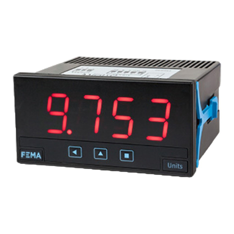
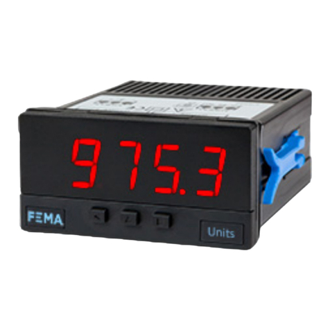
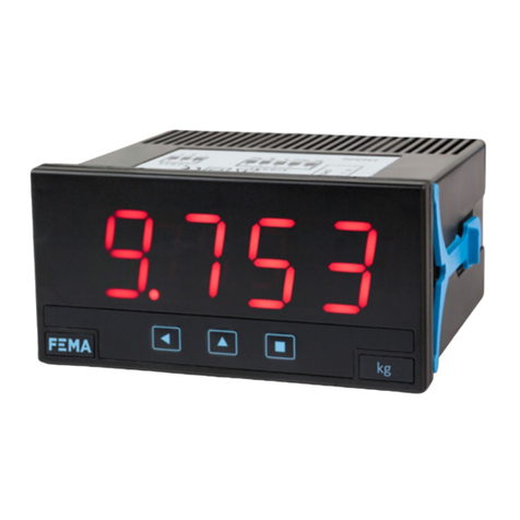
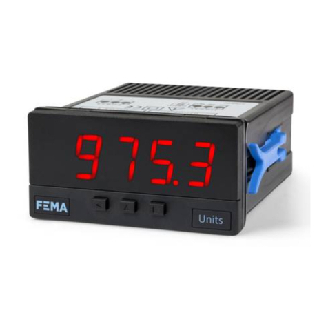
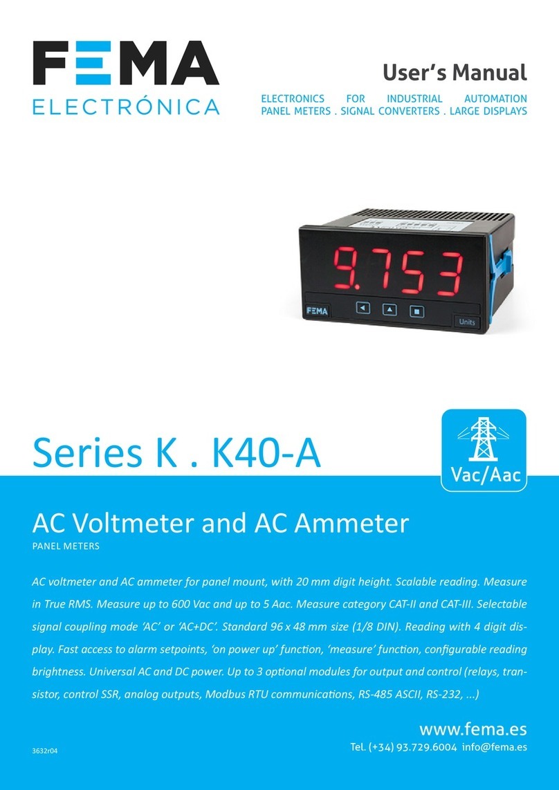
Display for ASCII protocol with RS-232 bus, in 96 x 48 mm (1/8 DIN) format
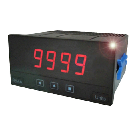
Digital panel meter, with ASCII code repeater funcon, in 96 x 48 mm
size (1/8 DIN) and 4 digits with 20 mm digit height. Reading value,
together with decimal point, are controlled via the RS-232 bus, us-
ing the ASCII protocol described in this document (see secon 1.13).
Reading up to 9999 and -1999.
Three working modes available allow to work with numbers or al-
phanumerical symbols. Alarms can be controlled directly from the
RS-232 bus or locally from the instrument.
• The ‘Process slave’ (see secon 1.2) mode works with numerical
values, and alarms are controlled locally.
• The ‘Full slave’ (see secon 1.3) mode works with numerical val-
ues, and alarms are controlled from the bus.
• The ‘Text’ (see secon 1.4) mode works with alphanumerical val-
ues, and alarms are controlled from the bus.
Bus speed congurable up to 38.400 bps and address congurable
from 1 to 31. Accepts a ‘broadcast’ funcon at address 128. ‘Watch-
dog’ funcon detects if communicaon with the master is lost.
‘Watchdog’ funcon can display a message on display and control
the acvaon of selected alarms (see secon 1.25).
Funcon ‘bus acvity’ is a ulity for troubleshoong communica-
ons (see secon 1.26). Funcon ‘On power up’ denes the alarm
state at start-up (see secon 1.28.8).
Front protecon IP65. Connecons by plug-in screw terminals. For
industrial applicaons.
• ‘Fast access’ menu to selected funcons, accessible with key UP (5)
(see secon 1.28.6)
Memory for maximum and minimum reading, password protecon,
5 brightness levels.
Index
1. Panel meter K40-232. . . . . . . . . . . . . . . . . . . . . . 2
1.1 How to order . . . . . . . . . . . . . . . . . . . . . . . . 3
1.2 ‘Process slave’ mode . . . . . . . . . . . . . . . . . . . . 3
1.3 ‘Full slave’ mode . . . . . . . . . . . . . . . . . . . . . . 3
1.4 ‘Text’ mode . . . . . . . . . . . . . . . . . . . . . . . . . 3
1.5 Typical applicaon . . . . . . . . . . . . . . . . . . . . . 3
1.6 Front view . . . . . . . . . . . . . . . . . . . . . . . . . . 4
1.7 Power connecons . . . . . . . . . . . . . . . . . . . . . 4
1.8 Start up sequence . . . . . . . . . . . . . . . . . . . . . 4
1.9 Rear view . . . . . . . . . . . . . . . . . . . . . . . . . . 4
1.10 Signal connecons . . . . . . . . . . . . . . . . . . . . 4
1.11 Technical specicaons . . . . . . . . . . . . . . . . . . 5
1.12 Mechanical dimensions (mm) . . . . . . . . . . . . . . 5
1.13 ASCII protocol - Types of frames . . . . . . . . . . . . . 6
1.14 Frame structure . . . . . . . . . . . . . . . . . . . . . . 7
1.15 Frame examples . . . . . . . . . . . . . . . . . . . . . . 8
1.15.1 Frames ‘WRA’ (35) and ‘OK’ (39) . . . . . . . . . . . 8
1.15.2 Frame ‘ERR’ (38) . . . . . . . . . . . . . . . . . . . . 8
1.15.3 Frames ‘PING’ (32) and ‘PONG’ (33) . . . . . . . . . 8
1.15.4 Frames ‘RD’ (36) and ‘ANS’ (37) . . . . . . . . . . . 9
1.16 Registers in ‘Process slave’ mode . . . . . . . . . . . .10
1.17 Registers in ‘Full slave’ mode. . . . . . . . . . . . . . .10
1.18 Registers in ‘Text’ mode . . . . . . . . . . . . . . . . . 11
1.19 CRC calculaon . . . . . . . . . . . . . . . . . . . . . . 11
1.20 The ‘Alarm status’ register . . . . . . . . . . . . . . . .12
1.21 Representable characters. . . . . . . . . . . . . . . . . 12
1.22 Messages and errors . . . . . . . . . . . . . . . . . . . 13
1.23 Numerical registers : restricons . . . . . . . . . . . .14
1.24 Addresses and ‘broadcast’ . . . . . . . . . . . . . . . .14
1.25 ‘Watchdog’ funcon . . . . . . . . . . . . . . . . . . . 14
1.26 ‘Bus acvity’ funcon . . . . . . . . . . . . . . . . . . . 14
1.27 How to operate the menus. . . . . . . . . . . . . . . . 15
1.28 Conguraon menu. . . . . . . . . . . . . . . . . . . . 16
1.28.1 Inial set-up . . . . . . . . . . . . . . . . . . . . . .16
1.28.2 Bus conguraon . . . . . . . . . . . . . . . . . . . 16
1.28.3 Conguraon . . . . . . . . . . . . . . . . . . . . .17
1.28.4 Alarms in ‘Full slave’ and ‘Text’ mode . . . . . . . .17
1.28.5 Alarms in ‘Process slave’ mode. . . . . . . . . . . .18
1.28.6 Fast access . . . . . . . . . . . . . . . . . . . . . . .19
1.28.7 Super fast access . . . . . . . . . . . . . . . . . . .19
1.28.8 Menu ‘On Power Up’ . . . . . . . . . . . . . . . . . 19
1.28.9 Menu ‘Setpoint on bus’ . . . . . . . . . . . . . . . . 19
1.28.10 Menu ‘Save to E2PROM’. . . . . . . . . . . . . . .20
1.28.11 Menu ‘Key LE’ . . . . . . . . . . . . . . . . . . . . 20
1.28.12 Funcon ‘Password’ . . . . . . . . . . . . . . . . .20
1.28.13 Factory reset . . . . . . . . . . . . . . . . . . . . .20
1.28.14 Firmware version. . . . . . . . . . . . . . . . . . . 20
1.28.15 Brightness . . . . . . . . . . . . . . . . . . . . . .20
1.28.16 Access to oponal modules . . . . . . . . . . . . . 20
1.29 Factory conguraon . . . . . . . . . . . . . . . . . . .21
1.30 Full conguraon menu . . . . . . . . . . . . . . . . . 22
1.31 To access the instrument . . . . . . . . . . . . . . . . .24
1.32 Modular system . . . . . . . . . . . . . . . . . . . . . .24
1.33 Precauons on installaon . . . . . . . . . . . . . . . .25
1.34 Warranty . . . . . . . . . . . . . . . . . . . . . . . . . .25
1.35 CE declaraon of conformity . . . . . . . . . . . . . . . 25
2. Output and control modules . . . . . . . . . . . . . . . . .26
2.1 Module R1. . . . . . . . . . . . . . . . . . . . . . . . . . 26
2.2 Module T1. . . . . . . . . . . . . . . . . . . . . . . . . .26
2.3 Module SSR . . . . . . . . . . . . . . . . . . . . . . . . .27
2.4 Module AO . . . . . . . . . . . . . . . . . . . . . . . . . 27
2.6 Module RTU. . . . . . . . . . . . . . . . . . . . . . . . . 28
2.5 Module S4. . . . . . . . . . . . . . . . . . . . . . . . . .28
2.7 Module S2. . . . . . . . . . . . . . . . . . . . . . . . . .29
2.8 Modules R2, R4, R6. . . . . . . . . . . . . . . . . . . . . 29
3. Other opons . . . . . . . . . . . . . . . . . . . . . . . . . . 30
3.1 Opon NBT . . . . . . . . . . . . . . . . . . . . . . . . . 30
4. Accessories . . . . . . . . . . . . . . . . . . . . . . . . . . .31
4.1 THM benchtop housing . . . . . . . . . . . . . . . . . . 31
4.2 Adapter DRA-M . . . . . . . . . . . . . . . . . . . . . . . 31
4.3 Adapter KA96 . . . . . . . . . . . . . . . . . . . . . . . .31
4.4 WME housing . . . . . . . . . . . . . . . . . . . . . . . .31
4.5 Protector KIP . . . . . . . . . . . . . . . . . . . . . . . .31


