FEMA ELECTRÓNICA . Series V . V4P
2
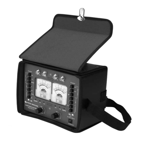
1. Panel meter V4P
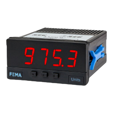
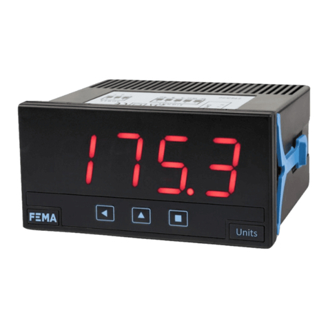
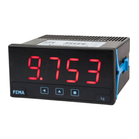
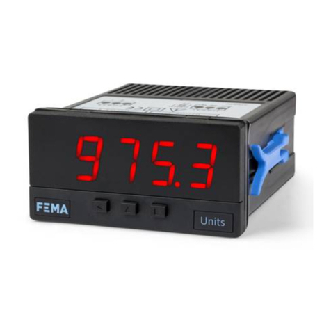
Compact meter 72 x 36 mm (9/128 DIN), mulsignal for OEM applicaons
Compact size 72 x 36 mm panel meter, mulsignal, for OEM applica-
ons. Accepts process signals (mA and Vdc) with excitaon voltage
included, thermocouples K, J, E, N, L, R, S, B, T and C, resisve tem-
perature probes (Pt100, Pt500, Pt1000, Ni100, Ni200, Ni1000, PTC
and NTC), resistances and potenometers. Scalable reading with 4
digits up to 9999 / -1999 with congurable decimal point.
Universal power supply 18 to 265 Vac/dc isolated. Connecons with
plug-in screw terminals.
Index
1. Panel meter V4P . . . . . . . . . . . . . . . . . . . . . . . . 2
1.1 How to order . . . . . . . . . . . . . . . . . . . . . . . . 2
1.2 Installaon and start-up . . . . . . . . . . . . . . . . . . 2
1.3 Front view . . . . . . . . . . . . . . . . . . . . . . . . . . 3
1.4 Rear view . . . . . . . . . . . . . . . . . . . . . . . . . . 3
1.5 Power connecons . . . . . . . . . . . . . . . . . . . . . 3
1.7 Mechanical dimensions (mm (in)). . . . . . . . . . . . . 3
1.6 Signal connecons . . . . . . . . . . . . . . . . . . . . . 3
1.8 Technical specicaons . . . . . . . . . . . . . . . . . . 4
1.9 Internal jumpers . . . . . . . . . . . . . . . . . . . . . . 5
1.10 Process measures . . . . . . . . . . . . . . . . . . . . . 6
1.11 Measuring thermocouples . . . . . . . . . . . . . . . . 7
1.12 Measuring with Pt and Ni probes . . . . . . . . . . . . 8
1.13 Measuring with NTC probes . . . . . . . . . . . . . . . 9
1.14 Measuring with PTC probes . . . . . . . . . . . . . . . 9
1.15 Measuring resistances . . . . . . . . . . . . . . . . . . 10
1.16 Measuring potenometers. . . . . . . . . . . . . . . . 10
1.17 Scaling . . . . . . . . . . . . . . . . . . . . . . . . . . .11
1.18 Oset reading . . . . . . . . . . . . . . . . . . . . . . .11
1.19 ‘Eco’ mode . . . . . . . . . . . . . . . . . . . . . . . . . 11
1.20 External control . . . . . . . . . . . . . . . . . . . . . .11
1.21 Second scaling . . . . . . . . . . . . . . . . . . . . . . . 11
1.22 Messages and errors . . . . . . . . . . . . . . . . . . . 11
1.23 Precauons on installaon . . . . . . . . . . . . . . . .12
1.24 Warranty . . . . . . . . . . . . . . . . . . . . . . . . . . 12
1.25 Factory conguraon . . . . . . . . . . . . . . . . . . .12
1.26 CE declaraon of conformity . . . . . . . . . . . . . . . 12
1.28 To open the instrument. . . . . . . . . . . . . . . . . . 13
1.27 How to operate the menus. . . . . . . . . . . . . . . . 13
1.29 Conguraon menu. . . . . . . . . . . . . . . . . . . . 14
1.29.1 Input signal ranges . . . . . . . . . . . . . . . . . . 14
1.29.2 Scaling . . . . . . . . . . . . . . . . . . . . . . . . . 15
1.29.3 Alarms . . . . . . . . . . . . . . . . . . . . . . . . . 15
1.29.4 External control . . . . . . . . . . . . . . . . . . . .15
1.29.5 Menu ‘Tools’ . . . . . . . . . . . . . . . . . . . . . . 16
1.30 Full conguraon menu . . . . . . . . . . . . . . . . . 18
Designed for industrial use, with potenal integraon in to a wide
range of applicaons, reduced cost, excellent quality and oponal
customizaon of the instrument.
• ‘Eco’ mode reduces power consumpon
(see secon 1.19).
• Simplied scaling conguraon (see secon 1.17).
• Funcon ‘external control’ to acvate special funcons through a
rear terminal (second scaling, decimal point, reading ‘hold’, ‘tare’)
(see secon 1.20).
• 5 congurable brightness levels (see secon 1.29.5).
1.1 How to order
V4P
Model Customizaon
-XXXX (customized)
-(empty)
-
The instrument is provided with the front lter not com-
pletely clipped. In this way it is easy to remove in order to
proceed to the rst conguraon of the instrument : inter-
nal jumpers and conguraon keypad. Once congured, you can
completely clip the front lter as indicated in the last of the steps
listed below.
1. Open the housing as indicated at secon 1.28 and access the
instrument internal board.
2. Select jumpers ‘S’ for the signal range required (see secon
1.9).
3. Select jumper ‘T’ to assign to mulfuncon terminal 5 the re-
quired funconality (see secon 1.9).
4. Reintroduce the instrument into the housing. Do not clip the
front lter yet.
5. Connect the power supply as indicated at secons 1.5.
6. Congure the instrument from the ‘conguraon menu’ (see
secon 1.29).
7. Close the instrument by placing the front lter as indicated at
secon 1.28.
8. Connect the input signal as indicated at secons 1.6.
1.2 Installaon and start-up
!
!When the “aenon” or “risk of electrical shock”
marks appear, read the documentaon for informa-
on on the nature of the risk.


