Fermax MDS-BUS2 User manual

TECHNICAL MANUAL
MDS - BUS2 SYSTEM
System Description
Section I

Code 97586I-1 V06_10Page 2
MDS - BMDS - B
MDS - BMDS - B
MDS - BUS2US2
US2US2
US2
MDS - BMDS - B
MDS - BMDS - B
MDS - BUS2US2
US2US2
US2
MDS-BUS2 TECHNICAL MANUAL
The MDS-BUS2 technical manual is comprised of two sections:
- Section I: Description of the MDS-BUS2 System (Code 97586I-1)
- Section II: MDS-BUS2 installation diagrams (Code 97586I-2)
MDS-BUS2 Technical Manual - Section I
Code 97586I-1 V06_10
This technical document of an informative nature is published by FERMAX ELECTRONICA S.A.E., who reserve the right to
modify the technical characteristics of the products referred to herein at any time and without prior notice. These changes will
be reflected in subsequent editions of this document.

Code 97586I-1 V06_10 Page 3
MDS - BMDS - B
MDS - BMDS - B
MDS - BUS2US2
US2US2
US2
MDS - BMDS - B
MDS - BMDS - B
MDS - BUS2US2
US2US2
US2
TABLE OF CONTENTS
SECTION I - DESCRIPTION OF MDS-BUS2 SYSTEM
MDS - BUS2 SYSTEM ................................................................................................................................................5
- Introduction: ...........................................................................................................................................................5
MDS-BUS2 DECODER ................................................................................................................................................6
- Overview .................................................................................................................................................................6
MDS-BUS2 SYSTEM PROGRAMMING ......................................................................................................................8
- BUS2 Decoder Programming via the MDS Digital Panel .........................................................................................8
- Interior Block Programming under Option "C" via the MDS Digital Panel ................................................................9
- BUS2 Decoder Programming via PC .................................................................................................................... 10
- Examples ............................................................................................................................................................ 11
- Programming BUS2 residential terminals via the interior blocks’ BUS2 panel ....................................................... 17
- Programming BUS2 residential terminals via the interior block’s MDS Digital general entrance panel ................... 18
MDS-BUS2 DECODER TECHNICAL FEATURES ...................................................................................................... 20
MDS-BUS2 SYSTEM SECTIONS TABLE ................................................................................................................. 21

Code 97586I-1 V06_10Page 4
MDS - BMDS - B
MDS - BMDS - B
MDS - BUS2US2
US2US2
US2
MDS - BMDS - B
MDS - BMDS - B
MDS - BUS2US2
US2US2
US2

Code 97586I-1 V06_10 Page 5
MDS - BMDS - B
MDS - BMDS - B
MDS - BUS2US2
US2US2
US2
MDS - BMDS - B
MDS - BMDS - B
MDS - BUS2US2
US2US2
US2
BLOCK 1
Introduction
The BUS2 DECODER allows the user combine MDS infrastructure on General Entrances (MDS DIGITAL NCity entry
panels) and on Interior Blocks, BUS2 equipment, panels and residential terminals.
This provides a wide range of possibilities, taking the best from each system: the multiple MDS functions (various access
points, guard unit/s, various interior blocks, greater distances .....etc) and the simplicity of a BUS2 system: UPT CAT2
twisted pair or PARALLEL Cable (based on distances and terminals). See BUS2 Technical Manual for more details.
This device is typically used to enclose various BUS2 blocks with one or various general entrances and a general guard
unit. The system within the block is entirely BUS2, and uses typical BUS2 components, while MDS elements are used
for General Entrances.
An MDS Digital central unit is used in General Entrances and digital panels with an electronic directory and/or central
guard unit are connected to it. In this case we can connect up to 10 central guard units and up to 32 panels. You can
also make use of all the additional functions an MDS Digital central unit offers: electronic directory, alarm sensors,
building automation, access control, lift control, etc....
MDS - BUS2 SYSTEM
EXAMPLE MDS - BUS2 SYSTEM
GENERAL ENTRANCE
MDS DIGITAL PANEL
CU
GUARD UNIT
MDS DIGITAL
BLOCK 2 n BLOCK
BUS2 PANEL BUS2 PANEL BUS2 PANEL

Code 97586I-1 V06_10Page 6
MDS - BMDS - B
MDS - BMDS - B
MDS - BUS2US2
US2US2
US2
MDS - BMDS - B
MDS - BMDS - B
MDS - BUS2US2
US2US2
US2
Overview
This device has been designed to combine MDS and BUS2 Interior Blocks.
Conversations within each block are independent, they can be held simultaneously with the entry panel or the general
entrance (either of these), this is because the BUS2 Decoder also acts as an audio changer, which when in standby
mode isolates audio within the block from the general entrance allowing the interior panels (BUS2) hold independent
conversations between their various residences. In this way it is possible to maintain simultaneous conversations in
different blocks, each one with their own interior panel. When a call is made from the general entrance to one of the
block’s residences the decoder connects the audio to the general entrance. If the call from the general entrance is
directed to another block the decoder disconnects the changer in such a way that the block’s audio is isolated once
again.
The BUS2 decoder should be installed preferably where the interior block power source is installed, together with the
video switcher where applicable. It is very important to use a power source for every interior block to avoid interference
between the signals generated from one block (calls, call confirmation tones, calls to guard unit etc).
A BUS2 decoder can manage between 1 and 199 residences (maximum allowed by BUS2) depending on how it is
configured.
There can be various construction types, even within the same building.
- Type A: Individual Chalets. This is the simplest case. A BUS2 decoder is used which responds to a unique chalet
address. The decoder output is set up in parallel with the chalet’s BUS2 kit panel and the residential terminal.
- Types B, C or D. Residential Buildings There are various options depending on each building’s capacity. The logical
thing is to choose certain digits to identify the block and others for the residences within the block.
Each residence has an assigned 4 digit call code for calls from the general entrance. These digits can be assigned in
the following manner:
Call Digits No of Blocks No of residences/per block Total residences
Type A (*) VVVV 9999 (0001..9999) 9999
Type B (*) BVVV 10 (0 .. 9) 199 (001..199) 1990
Type C: BBVV 100 (00 .. 99) 99 (01 .. 99) 9900
Type D (*) BBBV 1000 (000..999) 9 (1 .. 9) 9000
B: Block Digits.
V: Residence Digits
Type A -> Individual Residences. Maximum per development: 999 chalets/residences.
Type B -> Large Blocks (more than 100 residences). Maximum per development: 10 blocks with 199
residences per block, (allows you take advantage of the BUS2 system’s maximum capacity, 199
residences in each block).
Type C -> Medium Sized Blocks. Maximum per development: 100 blocks with 99 residences per block.
The most common type.
Type D - > Small Blocks. Maximum per development: 1000 blocks with 9 residences per block.
(*) Note: these options can only be used if MDS Digital Interior Blocks are used in the system (1
Decoder per central unit). See advanced diagrams.
MDS-BUS2 DECODER Ref. 3245

Code 97586I-1 V06_10 Page 7
MDS - BMDS - B
MDS - BMDS - B
MDS - BUS2US2
US2US2
US2
MDS - BMDS - B
MDS - BMDS - B
MDS - BUS2US2
US2US2
US2
The conversation time between the panel and the residence is limited:
- by the "maximum conversation time" parameter on MDS panels (which can range from 10 seconds to 4 minutes).
- by the BUS2 terminals’ own time settings (which limit the maximum conversation time to 90 seconds).
The time set will be the lower of these two.
If a call is made from an interior panel and then you try to call the same block from the MDS Digital general entrance, the
MDS Digital general entrance panel will indicate that the audio line is busy, to faciliate internal communication. This time
is set as the minimum conversation time established on the MDS Digital system.
VERY IMPORTANT
Calls from BUS2 interior panels can NEVER bypass the general entrance guard unit, nor can calls be made from
these interior panels to the guard units.
The limitations inherent to the BUS2 system within each block must be kept in mind (distance, section, power
supply).
Communication cannot be established within two residences even where an MDS guard unit is used, because
the BUS2 system does not facilitate it.
The BUS2 Decoder can act as a main panel, (it allows the user programme residential terminals from the
general entrance panel/guard unit) or alternatively as a secondary panel, (allows the user to programme residential
terminals from the Interior Block’s BUS2 panel). See programming section.
When calling residential terminals from the block programmed as 0, you don’t need to key in the initial zeros.
The BUS2 decoder responds to a range of telephones which should be programmed using an starting value and
an ending value. See programming section.
1 MDS Repeater will be needed Ref. 2339 where the MDS BUS includes more than 120 BUS2 Decoders, (1
Repeater will be connected every 120 decoders).
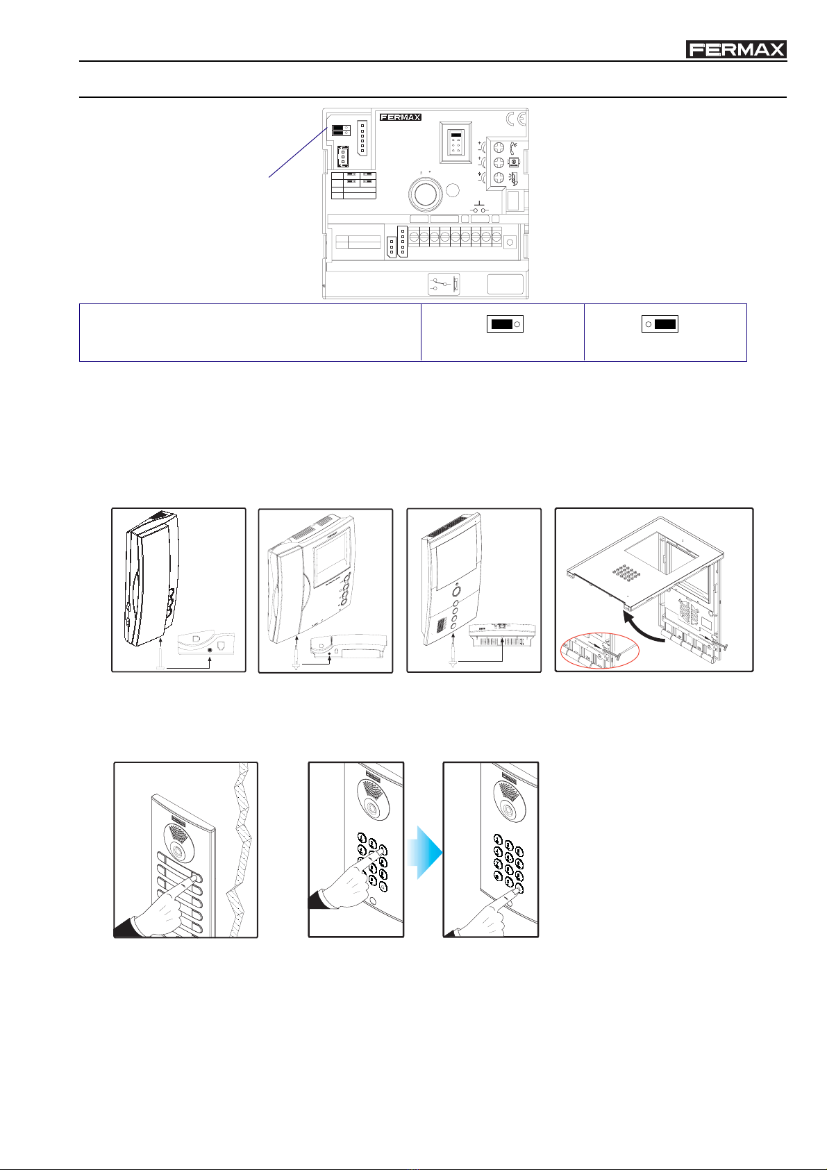
Status Led Operation:
1. BUS2 Bus Connector
2. MDS Bus Connector
3. PC Programming Connector
4. Programming button.
5. Activity Status Led
(See operation)
A. MDS Bus Connector
B. BUS2 Bus Connector
REF.3245
DL
REF.3245
DL
D2 26
D
-
+PC
CT V-
MDSBUS-2
VERSION
D2 2 6D-+
BB
PC
PGM
DECODER MDS-BUS2
CT V -
DIRECCIONES
ADDRESSES
INI. FIN.
B
B
2 3
5
4
3s 3s
off on off
off on on off
3s 3s
off
Not programmed Programmed: Guard unit does not receive calls Programmed: Guard unit receives calls

Code 97586I-1 V06_10Page 8
MDS - BMDS - B
MDS - BMDS - B
MDS - BUS2US2
US2US2
US2
MDS - BMDS - B
MDS - BMDS - B
MDS - BUS2US2
US2US2
US2
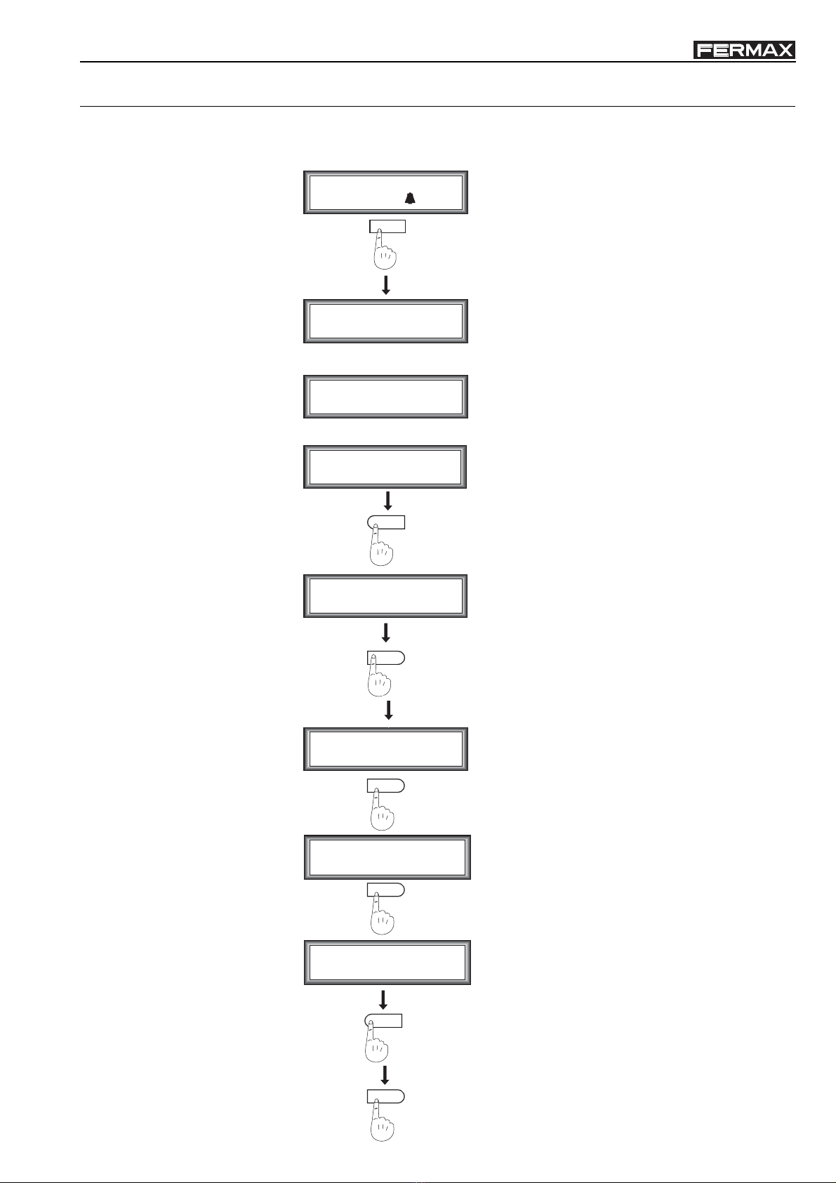
BUS2 Decoder Programming via the MDS Digital Panel
MDS-BUS2 SYSTEM PROGRAMMING
Enter
Programming Mode
1
Programming
BUS2 Decoder
(according to type)
2
2
Enter Code
------
AB21AB
0
Programming Code
-----
19025
DECODERS
- Individual pgm
Press PGM button
in decoder ...
Main Menu:
2 - DECODERS
B
Audio-4:
Telephone : _ _ _ _
Audio-4:
Telephone 2: _ _ _ _
Audio-4:
Telephone 3: _ _ _ _
Audio-4:
Telephone 4: FFFF
B
Tipo A, B, C o D
Search name
and press
See NOTES
(It can be substituted for another one)
Enter PROGRAMMING MODE
Programming Menu: DECODERS
Decoders Menu: INDIVIDUAL PROGRAMMING
PC
DECODER BUS2
BUS2 DECODER
DIRECCIONES
B
MDS
PGM
BUS2
DL
D2D
-
62
+
BCt V
M
PGM
Enter START ADDRESS: number assigned to the first
terminal connected to the BUS2 Decoder. (See NOTE 1).
Enter END ADDRESS: number assigned to the last
terminal connected to the BUS2 Decoder. (See NOTE 1).
0000 if the residential terminals are programmed from
the BUS2 panel. (See NOTE 2).
FFFF: : if the residential terminals are programmed from
the general entrance. (See NOTE 2).
FFFF: do not touch. (See NOTE 3).
To move to the
next display
once the data
has been
entered,
confirm
pressing
the "B" key
B
Code 97586I-1 V06_10 Page 9
MDS - BMDS - B
MDS - BMDS - B
MDS - BUS2US2
US2US2
US2
MDS - BMDS - B
MDS - BMDS - B
MDS - BUS2US2
US2US2
US2
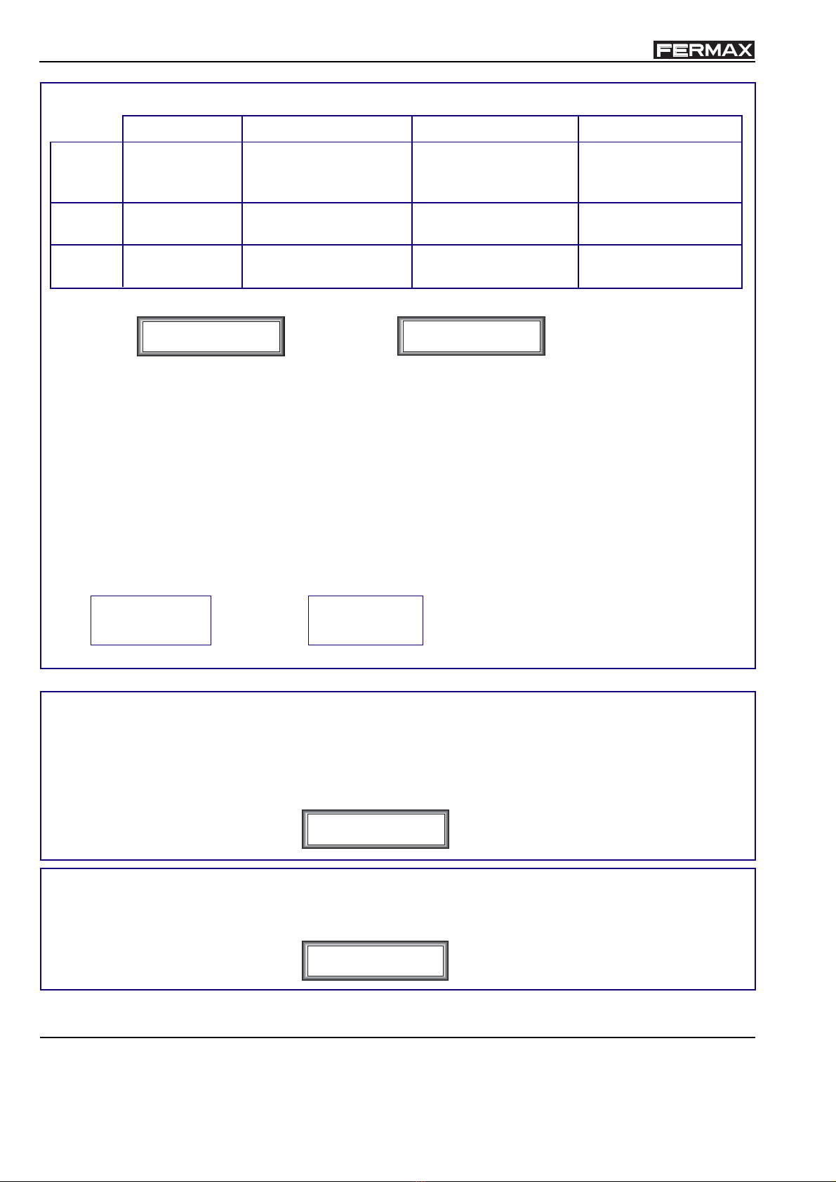
Interior Block Programming under Option "C" via the MDS Digital Panel
Enter Code
------
AB21AB
Search name
and press
0
Programming Code
-----
19025
Configuracion
6 - MDS - City
Press PGM button
in panel ...
B
Use blocks?
(A) - No. (B) - Yes.
6 digits Call?
(A) - No. (B) - Yes.
B
B
A
6
4
Main Menu:
4 - CONFIGURATION
(It can be substituted for another one)
Enter PROGRAMMING MODE
Programming Menu: CONFIGURATION
MDS-CITY
SKIP THIS STEP
PRESS "B"
CHOOSE "YES"
PRESS "B"
CHOOSE "NO"
PRESS "A"
EXIT
As described above there can be different types of set-up. If you choose option C, the Interior Block option should be
selected via the MDS DIGITAL Panel, as detailed below.
Code 97586I-1 V06_10Page 10
MDS - BMDS - B
MDS - BMDS - B
MDS - BUS2US2
US2US2
US2
MDS - BMDS - B
MDS - BMDS - B
MDS - BUS2US2
US2US2
US2
NOTE 2 -> The value is assigned.
- 0 0 0 0, if the residential terminals (telephone systems/monitors are going to be programmed via the Interior
Block’s BUS2 panel. See the section on programming the residential terminals from the interior block.
- F F F F, if the residential terminals (telephone systems/monitors are going to be programmed via the
General Entrance panel or guard unit. See the section on programming the residential terminals from
the general entrance.
NOTE 1 -> DECODER Address based on the set-up type (A, B, C or D):
Audio-4:
Telefono 3: _ _ _ _
Audio-4:
Telefono 4: FFFF
Audio-4:
Telefono : _ _ _ _
Start
Address
Audio-4:
Telefono 2: _ _ _ _
End
Address
Small Blocks:
- 9 Residences per block
- 999 Blocks
B =Block no. B B =Block no. B B B =Block no.
i i i i =f f f f
End
Address
Start
Address
TYPE A:
features Individual Chalet or
Residence
Large Blocks
- 199 Residences per block
- 9 Blocks
Medium Sized Blocks.
- 99 Residences per block
- 99 Blocks
i i i i
f f f f
TYPE B:
B i i i
B B f f
B B i i
B B f f
B B B i
B B B f
TYPE C: TYPE D:
Observations:
You can mix different types of set-ups within the same development but always respecting the following
LIMITATIONS:
a.) - Up to 9 Type B Blocks, (max. 199 Residences per block).
- Up to 99 Type C Blocks, (max. 99 Residences per block).
- Up to 999 Type D Blocks, (max. 9 Residences per block).
- Up to 9999 Type A Residences, (max. 9999 Individual Chalets or Residences).
b.) The same address should not be repeated on 2 different decoders, even where different TYPES of set-ups
are used.
Example: Cannot co-exist
BLOCK 1 BLOCK 11
RESIDENCE 115 RESIDENCE 15
as both have the address 115.
and
NOTE 3 -> Leave UNPROGRAMMED (F F F F).
If the value is re-set accidentally, the F F F F value can be re-assigned via the MDS DIGITAL panel using the
bell key.
VDS DECODER Programming via PC
a) Connect the decoder-PC interface to the CN3 connector. The decoder should use a +12V power supply on CN1.
(+, -). CN2 does not need to be powered up (+18V).
b) Start up the "Decowin" programme and select the "Decoders" "Programming" "Individual" option.
c) Follow the programme instructions. Request our DecoWin Programming Manual.

Code 97586I-1 V06_10 Page 11
MDS - BMDS - B
MDS - BMDS - B
MDS - BUS2US2
US2US2
US2
MDS - BMDS - B
MDS - BMDS - B
MDS - BUS2US2
US2US2
US2
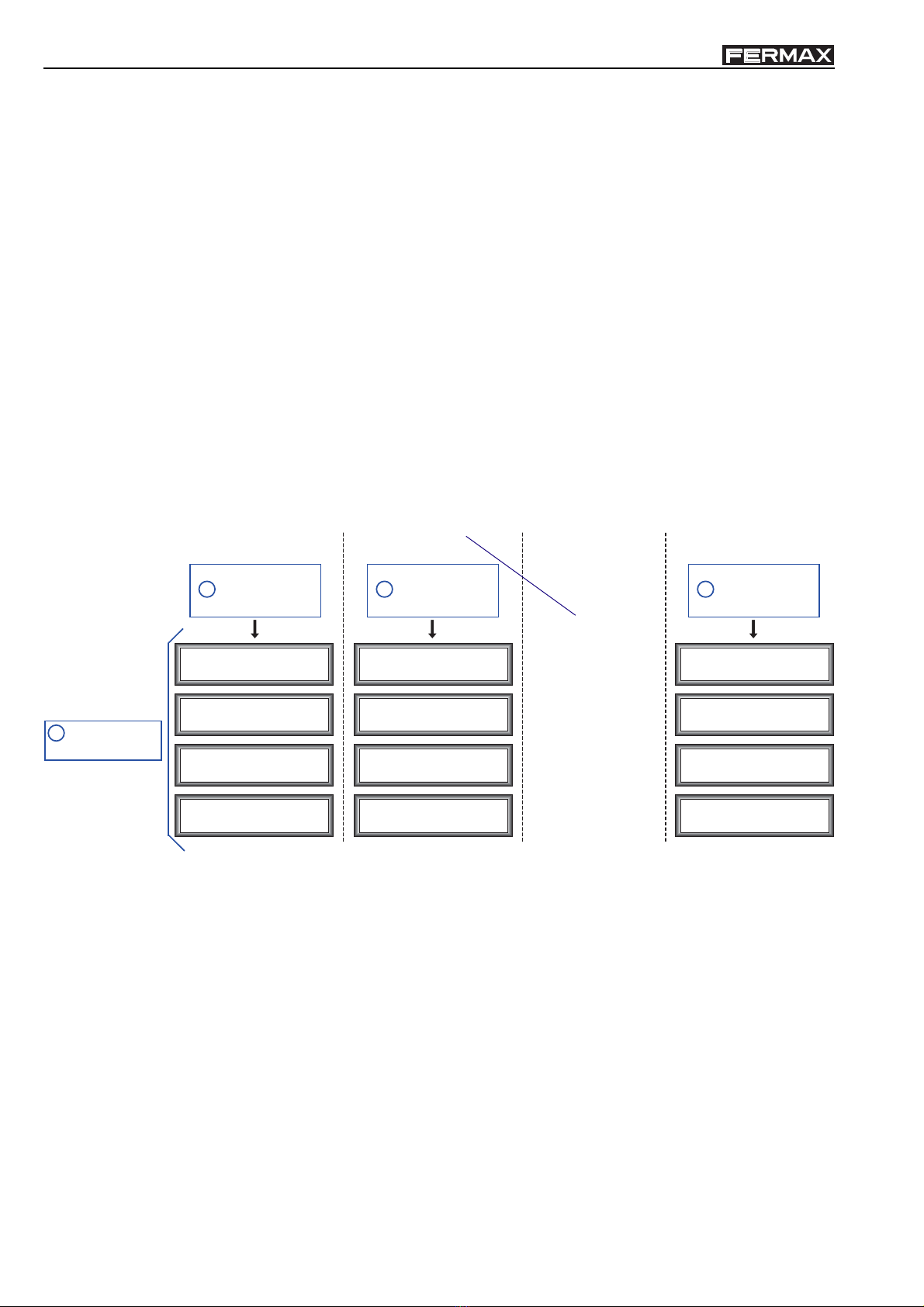
EXAMPLE 1:
16 block system (each block with a BUS2 panel).
* 10 Blocks with 45 residences each, (Block 1, 2, 3, 4, 5, 6, 7, 8, 9 and 10).
* 6 Blocks with 30 residences each, (Block 11, 12, 13, 14, 15 and 16).
Observations:
- The residences in each of the blocks should be numbered from 1 upwards.
- The residential terminals (monitors/telephones) should be programmed via the Interior Block’s BUS2 panel. See the
"Programming residential terminals via the INTERIOR BLOCK" section.
- Based on system features all the blocks would be TYPE C systems --> B B i i / B B f f, (Medium Sized Blocks, 99
residences per block and up to 99 blocks).
Programming:
1. Follow the steps for "Entering Programming Mode".
2. Follow the steps detailed in "Programming the BUS2 Decoder" (according to type), (there is one decoder per block).
Enter
STEPS
1
Programming mode
Enter
STEPS
1
Programming mode
Enter
STEPS
1
Programming mode
Audio-4:
Telephone : 1 1 0 1
Audio-4:
Telephone 2: 1 1 3 0
Audio-4:
Telefono 3: 0 0 0 0
Audio-4:
Telefono 4: F F F F
Block 11
(30 Apartments)
Audio-4:
Telephone : 1 2 0 1
Audio-4:
Telephone 2: 1 2 3 0
Audio-4:
Telephone 3: 0 0 0 0
Audio-4:
Telephone 4: F F F F
Block 12
(30 Apartments)
Audio-4:
Telephone : 1 0 1
Audio-4:
Telephone 2: 1 3 0
Audio-4:
Telephone 3: 0 0 0 0
Audio-4:
Telephone 4: F F F F
Block 1
(30 Apartments)
...................................
ADS Decoder
2
Programming
Blocks, 13, 14 and 15
(programmed in the same way)
Enter
STEPS
1
Programming mode
Enter
STEPS
1
Programming mode
Enter
STEPS
1
Programming mode
Audio-4:
Telephone : 0 1 0 1
Audio-4:
Telephone 3: 0 0 0 0
Audio-4:
Telephone 4: F F F F
Block 1
(45 Apartments)
Audio-4:
Telephone : 0 2 0 1
Audio-4:
Telephone 2: 0 2 4 5
Audio-4:
Telephone 3: 0 0 0 0
Audio-4:
Telephone 4: F F F F
Block 2
(45 Apartments)
Audio-4:
Telephone : 1 0 0 1
Audio-4:
Telephone 2: 1 0 4 5
Audio-4:
Telephone 3: 0 0 0 0
Audio-4:
Telephone 4: F F F F
Block 10
(45 Apartments)
...................................
Audio-4:
Telephone 2: 0 1 4 5
ADS Decoder
2
Programming
Blocks 3, 4, 5, 6, 7, 8, 9
(programmed in the same way)
Start Address
02: block no.
01: starting residence no.
End Address
02: block number
45: ending residence no.
0000 -> monitor/tele-
phone programming will
be done via the ADS
panel.
This output IS NOT
PROGRAMMED. Leave
as FFFF.
Examples
Code 97586I-1 V06_10Page 12
MDS - BMDS - B
MDS - BMDS - B
MDS - BUS2US2
US2US2
US2
MDS - BMDS - B
MDS - BMDS - B
MDS - BUS2US2
US2US2
US2
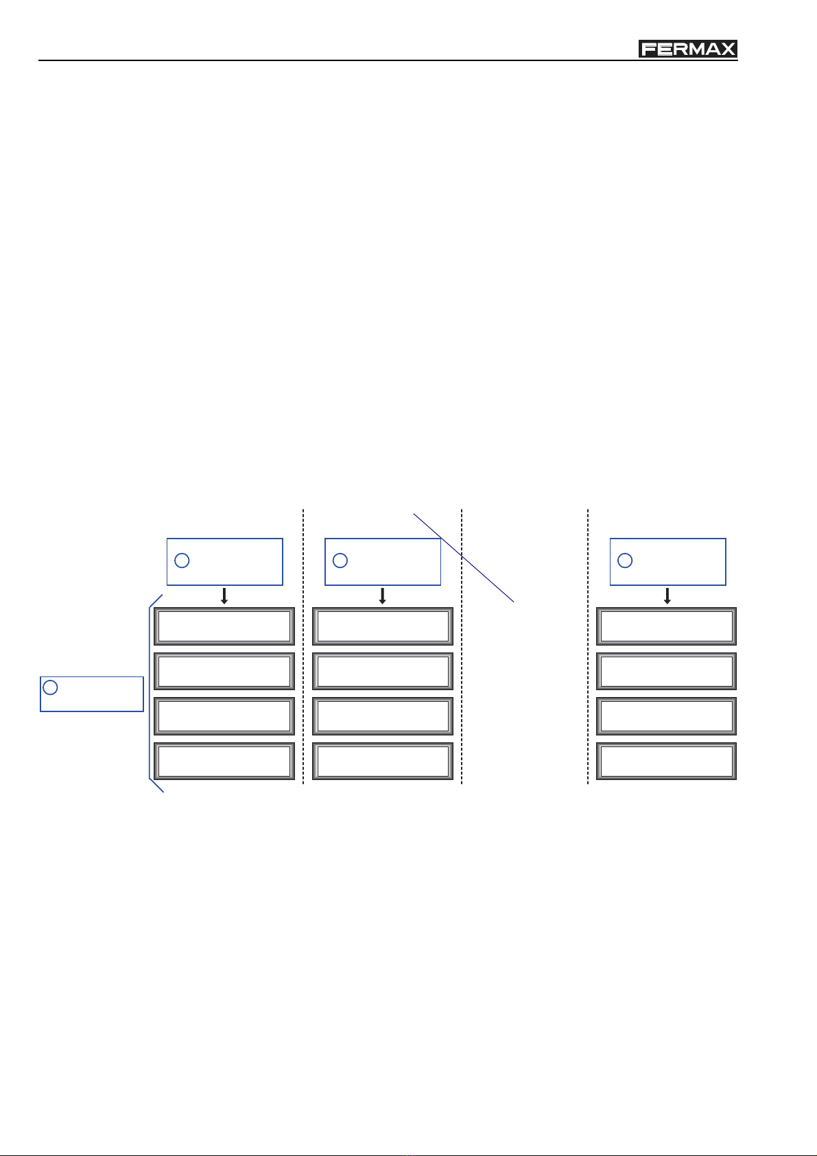
EXAMPLE 2:
230 Chalet System with a single 1 line panel on each one.
Observations:
- The chalets should be numbered from 1 upwards.
- The residential terminals (monitors/telephones) should be programmed via the Chalet’s BUS2 1 line panel. See the
"Programming residential terminals via the INTERIOR BLOCK" section.
- Based on the features of the system we would be in a TYPE A system --> i i i i / f f f f, (Chalets, up to 9999).
Programming:
1. Follow the steps for "Entering Programming Mode".
2. Follow the steps detailed in "Programming the BUS2 Decoder" (according to type), (there is one decoder per block).
Enter
STEPS
1
Programming mode
Enter
STEPS
1
Programming mode
Enter
STEPS
1
Programming mode
Audio-4:
Telephone : 0 0 0 1
Audio-4:
Telephone 2: 0 0 0 1
Audio-4:
Telephone 3: 0 0 0 0
Audio-4:
Telephone 4: F F F F
Chalet 1
( House)
Audio-4:
Telephone : 0 0 0 2
Audio-4:
Telephone 2: 0 0 0 2
Audio-4:
Telephone 3: 0 0 0 0
Audio-4:
Telephone 4: F F F F
Chalet 2
( House)
Audio-4:
Telephone : 0 2 3 0
Audio-4:
Telephone 2: 0 2 3 0
Audio-4:
Telephone 3: 0 0 0 0
Audio-4:
Telephone 4: F F F F
Chalet 230
( House)
...................................
ADS Decoder
2
Programming
Chalets 3 to 229
(programmed in the same way)
Start Address: 2
End Address: 2
0000 -> monitor/tele-
phone programming will
be done via the ADS
panel.
This output IS NOT
PROGRAMMED. Leave
as FFFF.

Code 97586I-1 V06_10 Page 13
MDS - BMDS - B
MDS - BMDS - B
MDS - BUS2US2
US2US2
US2
MDS - BMDS - B
MDS - BMDS - B
MDS - BUS2US2
US2US2
US2
EXAMPLE 3:
8 block system with 115 residences each, (each block has a BUS2 panel).
Observations:
- The residences in each of the blocks should be numbered from 1 upwards.
- The residential terminals (monitors/telephones) should be programmed via the General Entrance panel. See the
"Programming residential terminals via the GENERAL ENTRANCE" section.
- Based on system features all the blocks would be TYPE B systems --> B i i i / B f f f, (Large Blocks, 199 residences
per block and up to 9 blocks).
Programming:
1. Follow the steps for "Entering Programming Mode".
2. Follow the steps detailed in "Programming the BUS2 Decoder" (according to type), (there is one decoder per block).
Enter
STEPS
1
Programming mode
Enter
STEPS
1
Programming mode
Enter
STEPS
1
Programming mode
Audio-4:
Telephone : 1 0 0 1
Audio-4:
Telephone 2: 1 1 1 5
Audio-4:
Telephone 3: F F F F
Audio-4:
Telephone 4: F F F F
Block 1
( 5 Apartments)
Audio-4:
Telephone : 2 0 0 1
Audio-4:
Telephone 2: 2 1 1 5
Audio-4:
Telephone 3: F F F F
Audio-4:
Telephone 4: F F F F
Block 2
( 5 Apartments)
Audio-4:
Telephone : 8 0 0 1
Audio-4:
Telephone 2: 8 1 1 5
Audio-4:
Telephone 3: F F F F
Audio-4:
Telephone 4: F F F F
Block 8
( 5 Apartments)
...................................
ADS Decoder
2
Programming
Start Address
2: block number
001: starting residence
no.
End Address
2: block number
115: ending residence no.
FFFF -> monitor/tele-
phone programming will
be done via the E.G.
panel.
Blocks 3, 4, 5, 6, 7,
(programmed in the same way)
This output IS NOT
PROGRAMMED. Leave
as FFFF.
Code 97586I-1 V06_10Page 14
MDS - BMDS - B
MDS - BMDS - B
MDS - BUS2US2
US2US2
US2
MDS - BMDS - B
MDS - BMDS - B
MDS - BUS2US2
US2US2
US2
EXAMPLE 4:
10 block system with 45 residences each, (each block has a BUS2 panel).
Observations:
- All the residences in each block should be numbered from 1 upwards. Where we want the blocks to be numbered from
1 upwards even where there is no BUS2 panel we will number them Block 1, Block 2, ..... , etc., while calls from the
General Entrance will be numbered 1 0 1, 1 0 2, ... for Block 1. Then 2 0 1, 2 0 2, ... for Block 2, and so on for all the
blocks.
- As there is not a BUS2 panel for each block, we can only programme the residential terminals (monitors/telephones)
from the General Entrance. See the "Programming residential terminals via the GENERAL ENTRANCE" section.
- Based on system features all the blocks would be TYPE C systems --> B B i i / B B f f, (Medium Sized Blocks, 99
residences per block and up to 99 blocks).
Programming:
1. Follow the steps for "Entering Programming Mode".
2. Follow the steps detailed in "Programming the BUS2 Decoder" (according to type), (there is one decoder per block).
Enter
PASOS
1
Programming mode
Enter
PASOS
1
Programming mode
Enter
PASOS
1
Programming mode
Audio-4:
Telephone : 0 1 0 1
Audio-4:
Telephone 3: F F F F
Audio-4:
Telephone 4: F F F F
Block 1
(45 Apartments)
Audio-4:
Telephone : 0 2 0 1
Audio-4:
Telephone 2: 0 2 4 5
Audio-4:
Telephone 3: F F F F
Audio-4:
Telephone 4: F F F F
Block 2
(45 Apartments)
Audio-4:
Telephone : 1 0 0 1
Audio-4:
Telephone 2: 1 0 4 5
Audio-4:
Telephone 3: F F F F
Audio-4:
Telephone 4: F F F F
Block 10
(45 Apartments)
...................................
Audio-4:
Telephone 2: 0 1 4 5
ADS Decoder
2
Programming
Start Address
02: block number
01: starting residence no.
End Address
02: block number
45: ending residence no.r
This output IS NOT
PROGRAMMED. Leave
as FFFF.
Blocks 3, 4, 5, 6, 7, 8, 9
(programmed in the same way)
FFFF -> monitor/tele-
phone programming will
be done via the E.G.
panel.

Code 97586I-1 V06_10 Page 15
MDS - BMDS - B
MDS - BMDS - B
MDS - BUS2US2
US2US2
US2
MDS - BMDS - B
MDS - BMDS - B
MDS - BUS2US2
US2US2
US2
EXAMPLE 5:
10 block system, (each block with a BUS2 panel) and 80 chalets with a 1 line digital kit panel (BUS2) in each.
* 6 Blocks with 45 residences each, (Block 1, 2, 3, 4, 5 and 6).
* 4 Blocks with 30 residences each, (Block 7, 8, 9 and 10).
Observations:
- The residences in each of the blocks should be numbered from 1 upwards.
- The chalets should be numbered from 1 upwards.
- The residential terminals (monitors/telephones) should be programmed via the Block or Chalet’s BUS2 panel. See the
"Programming residential terminals via the INTERIOR BLOCK" section.
- Based on the system features this would be a:
Chalets. TYPE A --> i i i i / f f f f, (up to 9999).
Blocks: TYPE C --> B B i i / B B f f, (Medium Sized Blocks, 99 residences per block and up to 99 blocks).
Programming:
1. Follow the steps for "Entering Programming Mode".
2. Follow the steps detailed in "Programming the BUS2 Decoder" (according to type), (there is one decoder per block
and per chalet).
VERY IMPORTANT NOTE:
The same address should not be repeated on 2 different decoders, even where different TYPES of set-ups are used.
TYPE A: Chalets.
Enter
STEPS
1
Programming mode
Enter
STEPS
1
Programming mode
Enter
STEPS
1
Programming mode
Audio-4:
Telephone : 0 0 0 1
Audio-4:
Telephone 2: 0 0 0 1
Audio-4:
Telephone 3: 0 0 0 0
Audio-4:
Telephone 4: F F F F
Chalet 1
( House)
Audio-4:
Telephone : 0 0 0 2
Audio-4:
Telephone 2: 0 0 0 2
Audio-4:
Telephone 3: 0 0 0 0
Audio-4:
Telephone 4: F F F F
Chalet 2
( House)
Audio-4:
Telephone : 0 0 8 0
Audio-4:
Telephone 2: 0 0 8 0
Audio-4:
Telephone 3: 0 0 0 0
Audio-4:
Telephone 4: F F F F
Chalet 80
( House)
...................................
ADS Decoder
2
Programming
Chalets 3 to 79
(programmed in the same way)
Start Address: 2
End Address: 2
0000 -> monitor/tele-
phone programming will
be done via the ADS
panel.
This output IS NOT
PROGRAMMED. Leave
as FFFF.

Code 97586I-1 V06_10Page 16
MDS - BMDS - B
MDS - BMDS - B
MDS - BUS2US2
US2US2
US2
MDS - BMDS - B
MDS - BMDS - B
MDS - BUS2US2
US2US2
US2
TYPE C: Medium Sized Blocks.
Enter
PASOS
1
Programming mode
Enter
PASOS
1
Programming mode
Enter
PASOS
1
Programming mode
Audio-4:
Telephone : 0 1 0 1
Audio-4:
Telephone 2: 0 1 4 5
Audio-4:
Telephone 3: 0 0 0 0
Audio-4:
Telephone 4: F F F F
Block 1
(45 Apartments)
Audio-4:
Telephone : 0 2 0 1
Audio-4:
Telephone 2: 0 2 4 5
Audio-4:
Telephone 3: 0 0 0 0
Audio-4:
Telephone 4: F F F F
Block 2
(45 Apartments)
Audio-4:
Telephone : 0 0 1
Audio-4:
Telephone 2: 0 4 5
Audio-4:
Telephone 3: 0 0 0 0
Audio-4:
Telephone 4: F F F F
Block
(45 Apartments)
...................................
ADS Decoder
2
Programming
Blocks, 3, 4 and 5
(programmed in the same way)
Block 9
(programmed in the same way)
Enter
STEPS
1
Programming
Enter
STEPS
1
Programming
Enter
STEPS
1
Programming
Audio-4:
Telephone : 0 7 0 1
Audio-4:
Telephone 2: 0 7 3 0
Audio-4:
Telephone 3: 0 0 0 0
Audio-4:
Telephone 4: F F F F
Block 7
(30 Apartments)
Audio-4:
Telephone : 0 8 0 1
Audio-4:
Telephone 2: 0 8 3 0
Audio-4:
Telephone 3: 0 0 0 0
Audio-4:
Telephone 4: F F F F
Block 8
(30 Apartments)
Audio-4:
Telephone : 1 0 0 1
Audio-4:
Telephone 2: 1 0 3 0
Audio-4:
Telephone 3: 0 0 0 0
Audio-4:
Telephone 4: F F F F
Block 10
(30 Apartments)
...................................
ADS Decoder
2
Programming
Start Address
02: block number
01: starting residence no.
End Address
02: block number
45: ending residence no.
0000 -> monitor/tele-
phone programming will
be done via the ADS
panel.
This output IS NOT
PROGRAMMED. Leave
as FFFF.
Code 97586I-1 V06_10 Page 17
MDS - BMDS - B
MDS - BMDS - B
MDS - BUS2US2
US2US2
US2
MDS - BMDS - B
MDS - BMDS - B
MDS - BUS2US2
US2US2
US2
Programming BUS2 residential terminals via the interior blocks’ BUS2 panel, monitors and telephones.
The programming procedure for BUS2 terminals is the same for monitors and telephones.
The residential terminals will not function if they have not been programmed
Terminal programming is carried out in 2 steps:
PROG
.
PROG
.
1.- Terminal Programming Setup:
2.- Allocation of Call Codes
Loft Telephone Loft Monitor Compact Loft Monitor iLoft Monitor
Button Panels Keypad Panels
Press the residence’s
call button
Using the keypad, enter the call code
and press the bell
A time period of 2 minutes exists
within which to carry out step 2
after terminal programming
setup.
Once this time has passed, the
terminal will exit programming
mode.
The Loft Compact and iLoft monitors have an additional function which enables monitor programming from the same
monitor, without having to carry out any operation from the outdoor entry panel.
It is recommended that each of the Interior Block’s residences are programmed from 1 upwards.
A detailed description of the features and functions corresponding to each terminal is given in the technical documentation:
Manuals available on the Fermax website: www.fermax.com.
Press the monitor programming setup button.
i
Configuration switch:
JP2 : Main/Secondary Panel Selection Switch Secondary PanelMain Panel
JP3
JP2
CN
CN2
MIC
NC NO C -
BS
BUS-2
EXITEXIT
BB
+12
S
JP3
JP2
PACK EXTENSION
CN1
CN2
LEDS ON
SLAVE
MASTER
LEDS OFF
TARJETERO
CARD HOLDER
CN4
CN3
AUDIO
BUS-2 VERSTÄRKER
AMPLIFICATEUR BUS-2
BUS-2 AMPLIFIER
AMPLIFICADOR BUS-2
PROG
TEST
C
NO
NC
STATUS LEDS
LEDS ESTADO
VERSION :
LANGUAGE
IDIOMA
10
PAN & TILT
D
C
B
A
JP3 JP2
CN4
CN3
SW1
MIC
Leave the JP2 switch in
place as the MAIN Panel

Code 97586I-1 V06_10Page 18
MDS - BMDS - B
MDS - BMDS - B
MDS - BUS2US2
US2US2
US2
MDS - BMDS - B
MDS - BMDS - B
MDS - BUS2US2
US2US2
US2
4
2
0
See NOTE
Press lock release
in telephone ...
Starting Number:
0000
DECODERS MENU
PROGRAMMING
TELEPHONE
FINISHED OPERATION
B
Sequential
Programming
See NOTE
Attended
Programming
Prog. Telephone
-Pr. Attended
2
Prog. Telephone
2-Pr. Sequential
Press lock release
in telephone ...
See NOTE 2
ENTER
PROGRAMMING MODE
Programming Code
-----
19025
B
B
Search name
and press
Decoders
4 -Pr. Telephone
Main Menu
2 - Decoders
Enter Code
------
AB21AB
New : 0 0 0 0
Original: _ _ _ _
to do againto do again
BUS2 Residential terminal programming via the General Entrance MDS DIGITAL Panel
(It can be substituted for another one).
See NOTES on the next page.
Press the programming
set-up button on the
telephone or monitor.
PROG
.
PROG
.

Code 97586I-1 V06_10 Page 19
MDS - BMDS - B
MDS - BMDS - B
MDS - BUS2US2
US2US2
US2
MDS - BMDS - B
MDS - BMDS - B
MDS - BUS2US2
US2US2
US2
NOTES:
Remember that if you want to start the programming process from an MDS panel (including guard units) they
VDS decoder must have been pre-programmed as detailed under the "BUS2 Decoder Programming" section,
(Telephone 3: FFFF).
First make a call from the entry panel to any address in this block to activate the audio channel.
Telephone systems programmed with the sub-option "ANSWERED" will need one person on the entry panel and
another person to go from residence to residence. A conversation can be held between the person on the entry
panel and the residence to indicate what residence the other person is in.
Telephone systems programmed with the sub-option "SEQUENTIAL" should use consecutive numbers and just
need one person to go from residence to residence.
NOTE 1-> A message reading "press lock-release button on telephone system" will appear, but actually you
will need to press the programming button on the monitor or telephone.
NOTE 2-> The telephone’s current number will appear on the panel, or alternatively will be set to 0000 if it
hasn’t yet been programmed.
Audio-4:
Telefono 3: F F F F

Code 97586I-1 V06_10Page 20
MDS - BMDS - B
MDS - BMDS - B
MDS - BUS2US2
US2US2
US2
MDS - BMDS - B
MDS - BMDS - B
MDS - BUS2US2
US2US2
US2
Power Supply
12 Vdc
Consumption
standby: 20 mA
active: 30 mA
Operating Temperature: 0 ÷+50 ºC
Installation
Within a flush mounted box or within a building.
Connection Terminals
CN1: BUS2 System.
B, B: Power Supply and Data Signal (audio/video).
CN2: MDS System.
+,-: 12 Vdc power supply.
D1,D2:Decoder Bus Data. RS-485.
2, 6: MDS Audio Panels.
2: Entry Panel Audio Direction.
6: residence direction.
CN3:PC-Decoder interface connector for PC programming.
CN5: VIDEO System.
Ct: Video Activation.
V, -: Coaxial
* V: Live
* -: mesh
MDS-BUS2 DECODER TECHNICAL FEATURES
Status Led Operation:
3s 3s
off on off
off on on off
3s 3s
off
Not programmed Programmed: Guard unit does not receive calls Programmed: Guard unit receives calls
This manual suits for next models
1
Table of contents
Other Fermax Media Converter manuals

Fermax
Fermax 2426 User manual

Fermax
Fermax DECODER VDS User manual

Fermax
Fermax 2436 User manual

Fermax
Fermax DUOX PLUS User manual

Fermax
Fermax 2430 User manual

Fermax
Fermax 1300 Installation guide

Fermax
Fermax DUOX PLUS 9419 User manual

Fermax
Fermax DUOX User guide

Fermax
Fermax 2429 User manual

Fermax
Fermax DUOX PLUS 9419 User manual


