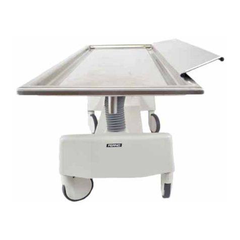
Ferno 103 User manual

Users’ Manual
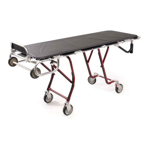
Model 103 Combination Table
August 2009 GLO
Pub. No. 234-0037-05
Read this Manual
and Retain for
Future Reference
FERNO®
Mortuary

2© Ferno-Washington, Inc 234-0037-05 August 2009
Model 103 Combination Table
© Copyright Ferno-Washington, Inc. All Rights Reserved.
USERS’ MANUAL
To request additional free users’ manuals,
contact Ferno Customer Relations, your
Ferno distributor, or visit www.ferno.com.
Disclaimer
This manual contains general instructions for the use, operation
and care of this product. The instructions are not all-inclusive. Safe
and proper use of this product is solely at the discretion of the
user. Safety information is included as a service to the user. All
other safety measures taken by the user should be within and under
consideration of applicable regulations. It is recommended that
training on the proper use of this product be provided before using
this product in an actual situation.
Retain this manual for future reference. Include it with the product
in the event of transfer to new users. Additional free copies are
available upon request from Customer Relations.
Proprietary Notice
The information disclosed in this manual is the property of Ferno-
Washington, Inc., Wilmington, Ohio, USA. Ferno-Washington, Inc.
reserves all patent rights, proprietary design rights, manufacturing
rights, reproduction use rights, and sales use rights thereto, and
to any article disclosed therein except to the extent those rights
are expressly granted to others or where not applicable to vendor
proprietary parts.
Limited Warranty Statement
The products sold by Ferno are covered by a limited warranty,
which is printed on the invoice you received when you purchased
the product. Please refer to the warranty terms as printed on
your invoice. The complete terms and conditions of the limited
warranty, and the limitations of liability and disclaimers, are also
available upon request by calling Ferno at 1.800.733.3766 or
1.937.382.1451.
Ferno Customer Relations
For ordering assistance or general information:
CANADA AND THE U.S.A.
Telephone (Toll-free) 1.877.733.0911
Telephone 1.937.382.1451
Fax (Toll-free) 1.888.388.1349
Fax 1.937.382.1191
Internet www.ferno.com
ALL OTHER LOCATIONS
For assistance or information, please contact your Ferno distributor.
If you do not have a Ferno distributor, please contact Ferno
Customer Relations:
Ferno-Washington, Inc.
70 Weil Way
Wilmington, Ohio 45177-9371, U.S.A.
Telephone +1.937.382.1451
Fax +1.937.382.6569
Internet www.ferno.com
Ferno Technical Support
Customer service and product support are important aspects of each
Ferno product. Please have the product serial number available
when calling, and include it in all written communications. For
technical support questions:
Telephone (Toll-free) 1.800.733.3766 ext. 1010
Telephone 1.937.382.1451 ext. 1010
Email quality[email protected]
Serial Number _________________________
Location: Lower Frame of Table End
3
© Ferno-Washington, Inc 234-0037-05 August 2009
Model 103 Combination Table
TABLE OF CONTENTS
Section Page Section Page
Ferno Customer Relations______________________ 2
Ferno Technical Support _______________________ 2
1 - Safety Information___________________________ 4
1.1 Warning________________________________ 4
1.2 Important_______________________________ 4
1.3 Bloodborne Disease Notice_________________ 4
1.4 Symbol Glossary_________________________ 4
1.5 Safety and Instruction Labels _______________ 5
2 - Operator Skills and Training __________________ 5
2.1 Skills __________________________________ 5
2.2 Training________________________________ 5
3 - About the Table _____________________________ 6
3.1 Description _____________________________ 6
3.2 GeneralSpecications ____________________ 6
3.3 Components ____________________________ 7
4 - Setup ______________________________________ 8
4.1 Attach the Lower Rails And Table Ends_______ 8
4.2 Attach Frame Braces______________________ 8
4.3 Attach the Table Top ______________________ 9
4.4 Remove the Ratchet Pins __________________ 9
5 - Using the Table_____________________________ 10
5.1 Before Placing the Table in Service _________ 10
5.2 General Guidelines for Use________________ 10
5.3 Swivel Locks___________________________ 10
5.4 Adjusting the Height of the Table Top _______ 11
6 - Maintenance _______________________________ 12
6.1 Maintenance Schedule ___________________ 12
6.2 Disinfecting and Cleaning the Table_________ 12
6.3 Inspecting the Table _____________________ 12
6.4 Waxing the Table Legs and Frame __________ 13
6.5 Lubricating the Table ____________________ 13
7 - Accessories and Related Products _____________ 13
8 - Parts and Service ___________________________ 14
8.1 U.S.A. and Canada ______________________ 14
8.2 Worldwide_____________________________ 14
8.3 Parts List ______________________________ 14
Training Record ______________________________ 15
Maintenance Record___________________________ 15

4© Ferno-Washington, Inc 234-0037-05 August 2009
Model 103 Combination Table
1 SAFETY INFORMATION
1.1 Warning
Warning notices indicate a potentially hazardous situation
which, if not avoided, could result in injury or death.
WARNING
Untrained operators can cause injury or be injured. Permit
only trained personnel to operate the table.
Improper use of the table can cause injury. Use the table
only for the purpose described in this manual.
Improper operation can cause injury. Operate the table
only as described in this manual.
Improper maintenance can cause injury. Maintain the
table only as described in this manual.
Attaching improper items to the table can cause injury.
Use only Ferno-approved items on the table.
Improper parts and service can cause injury. Use only
Ferno parts and Ferno-approved service on the table.
Modifying the table can cause injury and damage. Use
the table only as designed by Ferno.
1.2 Important
Important notices emphasize important usage or maintenance
information.
Important
1.3 Bloodborne Disease Notice
To reduce the risk of exposure to bloodborne diseases such
as HIV-1 and hepatitis when using the table, follow the
disinfecting and cleaning instructions in this manual.
Safety Information
1.4 Symbol Glossary
The symbols dened below are used on the table and in
this users’ manual. Ferno uses symbols recognized by the
International Standards Organization (ISO), American
National Standards Institute (ANSI) and the mortuary
services industry.
General Warning
of Potential Injury
Unlocked Locked
Product meets European
Union Standards
Do Not
Lubricate
Lubricate
Read the Users’
Manual
Load Limit
Operation Requires
One Trained Operator

5
© Ferno-Washington, Inc 234-0037-05 August 2009
Model 103 Combination Table
1.5 Safety and Instruction Labels
Safety and instruction labels place important information from the users’manual on the table. Read and follow label instructions.
Replace worn or damaged labels immediately. New labels are available from EMSAR (page 14) or from your distributor. The
labelshownbelowisafxedtothebottomofthetable.
Safety Information, Skills and Training
2 OPERATOR SKILLS AND TRAINING
2.1 Skills
Operators using the table need:
a working knowledge of mortuary-service procedures.●
a complete understanding of the procedures described●
in this manual.
WARNING
Untrained operators can cause injury or be injured.
Permit only trained personnel to operate the table.
2.2 Training
Operator trainees need to:
read and understand this manual.●
be trained on the use of the table.●
practice with the table before using it with a body.●
record their training information. A sample training●
record sheet is provided on page 15.

6© Ferno-Washington, Inc 234-0037-05 August 2009
Model 103 Combination Table
3 ABOUT THE TABLE
3.1 Description
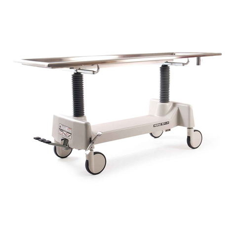
The Model 103 Combination Table (called the table in this
manual) is a mortuary-service product designed to provide
an adjustable surface for embalming, transfer, and dressing.
The table-top is constructed of stainless steel. The table has
a total of seven level locking positions and can be adjusted
between 31-1/2" and 37-1/2" at one or both ends. The table-
topisconvexandhasadeepperimetertroughtoguideuids
to a drain at the foot end.
The table has 6" (15 cm) caster wheels that swivel and lock.
INCLUDED WITH PURCHASE
A 3/16" Allen wrench is included with the purchase of a
table.
WARNING
Improper use of the table can cause injury. Use
the table only for the purpose described in this
manual.
About the Table
Load Limit
Inspect the table if the load limit
has been exceeded (See Inspecting
the Table, page 12).
USERS’ MANUAL
To request additional free users’ manuals,
contact Ferno Customer Relations, your
Ferno distributor, or visit www.ferno.com.
3.2 General Specications
Height
Minimum 31-1/2 in./80 cm
Maximum 37-1/2 in./95 cm
Length 80 in./205 cm
Width (Overall) 30 in./77 cm
Wheelbase 27 x 53 in./69 x 135 cm
Weight 80 lb/36 kg
Load Limit 1000 lb/454 kg
Generalspecicationsare rounded to the nearest whole number.
Metric conversions are calculated before rounding the Imperial
measurements. For more information, contact Ferno Customer
Relations (page 2) or your Ferno distributor.
Fernoreservestherighttochangespecicationswithoutnotice.

7
© Ferno-Washington, Inc 234-0037-05 August 2009
Model 103 Combination Table About the Table
3.3 Components
Table Top
Drain
Trough
Ratchet
Control Bar
(Each End)
Wheel Swivel
Lock (4)

8© Ferno-Washington, Inc 234-0037-05 August 2009
Model 103 Combination Table
4 SETUP
Setup
Follow the instructions in this section to prepare the table for use. All hardware is supplied.
4.2 Attach Frame Braces
Use a #2 Phillips screwdriver to attach the four frame
braces to the lower rails and corner posts using the
eight Phillips pan-head screws provided (Figure 2).
Frame Brace
Phillips
Pan-Head
Screw
Figure 2 - Attaching the Frame Braces
4.1 Attach the Lower Rails
And Table Ends
One Allen-head screw and two lock washers are1.
threaded into each of the four table-end wheel
castings. Remove these parts from their shipping
positions using the 3/16" Allen wrench provided
with the table.
Insert the lower rails into the table-end corner2.
castings (Figure 1). Verify that the holes for the
frame braces and table-ends are properly aligned
as follows:
The frame-brace mounting holes must face○
straight upward as shown in Figure 1 (not at
an angle).
The holes at the ends of the lower-rails are○
angled to properly align with the table-end
castings. After inserting the lower rails into
the table ends, verify that these holes are
visible in the table-end castings.
If the holes in the lower rail are not visible○
inside the table-end castings OR if the
frame-brace holes are not facing straight
up, turn the lower rail end-for-end.
Verify that there are two lock washers on each of3.
the four Allen-head mounting screws.
Secure the rails to the table ends using the 3/16"4.
Allen wrench and four socket-head cap screws
provided (Figure 1 inset).
Lower Rail (2)
Frame-Brace
Mounting Hole (4)
Table End (2)
Figure 1 - Attaching the Lower Rails and Table Ends
Socket-Head
Cap Screw (4)

9
© Ferno-Washington, Inc 234-0037-05 August 2009
Model 103 Combination Table Setup
4.3 Attach the Table Top
Before attaching the table top to the lower frame, be
aware of the following:
The table top is heavy. Use a minimum of two●
people to attach the table top to the lower frame.
There are cotter pins inside each of the four●
corner posts. DO NOT REMOVE the cotter pins
at this time.
The inside of the table-end frame tube is●
lubricated at the factory. You should not need to
lubricate the ratchet tubes during initial setup.
Using a minimum of two people, lift the table top1.
above the lower frame.
Align the ratchet tubes on the table top with the2.
corner posts on the table ends (Figure 3), then
lower the table top into the corner posts
4.4 Remove the Ratchet Pins
During assembly and shipping, the ratchet1.
control handles are held in the open position by
a small cotter pin inserted in each corner-post
casting.Useneedle-nosepliersorasmallathead
screwdriver to remove and discard the four pins
before placing the table in service (Figure 4).
Inspect the table before placing the table in2.
service. See Inspecting the Table, page 12.
Figure 4 - Remove the Four Pins
Pin
(4)
Figure 3 - Align the Table Top with the Corner Posts
Important
Do not remove the cotter pins from the four corner posts until
AFTER the table top has been inserted into the corner posts.

10 © Ferno-Washington, Inc 234-0037-05 August 2009
Model 103 Combination TableUsing the Table
5 USING THE TABLE
5.1 Before Placing the Table in Service
Personnel who will work with the table need to read this●
manual.
Set up the table, following the instructions in the● Setup section
on pages 8 and 9.
Conrmthatthetableoperatesproperly.See● Inspecting the
Table, page 12.
5.2 General Guidelines for Use
The table is for professional use only, by a trained operator.●
Follow standard mortuary-service procedures when using●
the table.
Lift only the weight you can safely handle. Use additional●
help when working with a heavy body.
Operation Requires
One Trained Operator Load Limit
WARNING
Improper operation can cause injury. Operate
the table only as described in this manual.
5.3 Swivel Locks
Eachof the fourwheels is ttedwith a lockingcaster. Lock the
casters to help hold the table steady and unlock the casters to roll
the table.
To lock a caster, turn the swivel lock toward the end of the●
table (Figure 5).
To unlock the caster, turn the swivel lock toward either of the●
long sides of the table (Figure 5).
To help prevent the table from rolling during use, lock the●
casters at 90° angles as shown in Figure 6:
(1) Align two wheels of opposite corners parallel to the
long sides of the table and lock them.
(2) Turn the remaining two wheels perpendicular to the
long sides of the table and lock them.
Figure 5 - Using the Swivel Lock
Figure 6 - Conguring the Casters
To Hold the Table Stationary
Caster (4)

11
© Ferno-Washington, Inc 234-0037-05 August 2009
Model 103 Combination Table Using the Table
5.4 Adjusting the Height
of the Table Top
The table top is adjustable between seven level positions.
Each end of the table can be adjusted independently. To tilt
the table top, raise one end of the table higher than the other.
Raising the end opposite of the drain will assistNote:
draining.
RAISING THE TABLE TOP
Grasp one end of the table with both hands and lift1.
slightly to assume the weight of the table top and
body. Use additional help as needed to help control the
weight of a heavy body.
Press downward on the crossbar with one foot as you2.
raise the table top a little higher than the desired height
(Figure 7).
Slowly lower the table top until it locks into the nearest3.
locking position.
If keeping the table level, move to the opposite end of4.
the table and repeat Steps 1-3.
LOWERING THE TABLE TOP
Stand at the end of the table you wish to lower.1.
With one hand, grasp the table top and lift slightly2.
to assume the weight of the table top and body. Use
additional help as needed to help control the weight of
a heavy body.
Placing your other hand3. in the center of the ratchet
control bar (Figure 8), pull and hold the ratchet
control bar to disengage the lock, then lower the table
top until it is almost the desired height.
Release the ratchet control bar and continue lowering4.
the table top until it locks into the nearest locking
position.
If keeping the table level, move to the opposite end of5.
the table and repeat Steps 1-4.
Figure 7 - Raising the Table Top
Figure 8 - Grasp the Center of the Ratchet Control Bar
When Lowering the Table Top

12 © Ferno-Washington, Inc 234-0037-05 August 2009
Model 103 Combination Table
6 MAINTENANCE
6.1 Maintenance Schedule
The table requires regular maintenance. Set up and follow
a maintenance schedule. The table at right represents
minimum intervals for maintenance.
Keep maintenance records. A sample maintenance record
sheet is provided on page 15.
When using maintenance products, follow the manufacturers’
directions and read the manufacturers’ material safety data
sheets. You can purchase a recommended disinfectant from
your Ferno distributor or Ferno Customer Relations (page 2).
WARNING
Improper maintenance can cause injury. Maintain
the table only as described in this manual.
Maintenance
6.2 Disinfecting and Cleaning
the Table
Ferno recommends inspecting the table for visible wear and
damage as you disinfect and clean it.
To disinfect:● Apply disinfectant to all surfaces
according to the disinfectant manufacturer’s
instructions for application method and contact time.
To clean:● Hand wash all parts of the table with warm
water and a mild detergent. Rinse with warm, clear
water. Dry with a towel or allow the table to air-dry.
Important
Disinfectants and cleaners containing bleach,
phenolics, or iodines can cause damage. Do not use
products containing these chemicals.
Important
Using abrasive cleaning compounds or applicators
on the table can cause damage. Do not use abrasive
materials to clean the table.
Important
Water under high pressure, or steam, can penetrate
joints, ush away lubricant, and cause corrosion. Use
caution when cleaning moving parts such as joints and
hinges, and reapply lubricant if needed.
6.3 Inspecting the Table
Inspect the table regularly. Follow the checklist below and
operate the table through all its functions as described in
this manual.
If inspection shows damage or excessive wear, remove
the table from service until repair is made. See Parts and
Service, page 14.
INSPECTION CHECKLIST
Are all components present?●
Is the table free of excessive wear?●
Are all screws, nuts, bolts and roll pins securely in●
place?
Do all moving parts operate smoothly and properly?●
Does each end of the table top lock properly into all●
six raised positions?
Do the wheels roll without wobbling and are the tires●
free of abrasions and wear?
Do the casters lock and unlock properly?●
Minimum
Maintenance Intervals
Each Use
As Needed
Each Month
Disinfecting (this page) •
Cleaning (this page) •
Inspecting (this page) • •
Waxing (page 13) •
Lubricating (page 13) •

13
© Ferno-Washington, Inc 234-0037-05 August 2009
Model 103 Combination Table Maintenance, Accessories
6.4 Waxing the Table Legs and Frame
While it is not necessary to wax this table, waxing the
aluminum legs and lower frame will not damage them, and
will maintain the table's appearance. Do not wax the table
top, which is constructed of stainless steel.
Disinfect and clean the table before applying wax. Use an
automotive wax as directed by the wax manufacturer.
6.5 Lubricating the Table
Disinfect and clean the table before applying lubricant. Use
the lubricants designated below to lubricate the table. Do not
lubricate points marked with the “do not lubricate” symbol.
Do Not Lubricate Lubricate
Important
Lubricating parts that should not be lubricated allows
dirt and foreign particles to collect on those parts,
resulting in damage. Lubricate only the numbered
reference points shown.
LUBRICATION POINTS
Use a small amount of lubricant. Lubricate identical
points on each side of the table.
1. Ratchet tubes (4) White lithium grease
2. Wheel Bearing (4) WRL-191S or E-Z-1 (1-2 drops)
LUBRICATIONFREE ITEMS
Ratchet control bar spring Do not lubricate
7 ACCESSORIES AND RELATED PRODUCTS
Ferno offers a full line of mortuary service accessories
and products. Always follow the instructions packed with
accessories. Keep the instructions with this manual. Be
aware of any special considerations (loading heights, door
widths, etc.) when using accessories.
Contact Ferno Customer Relations (page 2) or your Ferno
distributor for product information.
WARNING
Attaching improper items to the table can cause
injury. Use only Ferno-approved items on the table.
Model Description Part Number
14 Body Lifter 010-1400
38-BB Body Bridge 069-5790
Ultra Care 4000™Body/Casket Lift (U.S.A.) 066-3914
Ultra Care 4000™Body/Casket Lift (50 Hz) 066-3915
2
1

14 © Ferno-Washington, Inc 234-0037-05 August 2009
Model 103 Combination Table
8.2 Worldwide
To order Ferno parts and for professional repair, contact your
Ferno distributor. Your distributor is the only agent authorized
by Ferno to manage, service, and repair Ferno products.
8 PARTS AND SERVICE
8.1 U.S.A. and Canada
IntheUnitedStatesandCanada,toorderpartsorforprofessional
table repair, contact EMSAR®- the only agent authorized by
Ferno to manage, service, and repair Ferno products.
Telephone (Toll-Free) 1.800.73.EMSAR
Telephone 1.937.383.1052
Fax +1.937.383.1051
Internet www.EMSAR.com
WARNING
Improper parts and service can cause injury. Use
only Ferno parts and Ferno-approved service on the
table.
WARNING
Modifying the table can cause injury and damage.
Use the table only as designed by Ferno.
Parts and Service
8.3 Parts List
No. Part Description Qty
1 090-0930 Upper frame and braces (no table-top) 1
2 090-5530 Table-top (stainless steel, bolt-on, no frame)* 1
3 090-0871 Ratchet tube w/hardware Model 103 1
4 090-0350 End frame assy. (without casters) 1
5 090-0320 Lower frame rail 2
6 090-0791 Diagonal brace w/hardware 1
7 090-0793 Lock bar w/springs 1
8 090-0796 6" Swivel caster assy.
(Serial Number K-13739 and higher) 1
9 090-2904 6" Wheel w/bearing 1
10 190-1783 Label sheet 1
*Replacement stainless-steel table-top "skin" only, without tube frame.
This is a bolt-on version. All earlier versions are unavailable.
1
3
4
5
6
7
98
10 Not Shown
2

15
© Ferno-Washington, Inc 234-0037-05 August 2009
Model 103 Combination Table
TRAINING RECORD
Date Name Training Method
MAINTENANCE RECORD
Date Maintenance Performed By
Table of contents
Other Ferno Medical Equipment manuals

Ferno
Ferno One Man 27-1 User manual

Ferno
Ferno PRO F1 User manual

Ferno
Ferno 50-E User manual

Ferno
Ferno Pedi-Mate 678 User manual

Ferno
Ferno Mobile Transporter 35A Series User manual

Ferno
Ferno Kit 069-5796 User manual

Ferno
Ferno Mini Cot User manual

Ferno
Ferno Child EasyFix Manual

Ferno
Ferno 101-H User manual

Ferno
Ferno 125 User manual

Ferno
Ferno CCT Six-P User manual

Ferno
Ferno PEZO2 User manual

Ferno
Ferno Viper Stretcher User manual

Ferno
Ferno PROFlexX User manual

Ferno
Ferno 175 Series Reference manual

Ferno
Ferno COMPACT 1 CARRY CHAIR User manual

Ferno
Ferno 24 MAXX User manual

Ferno
Ferno CHI User manual

Ferno
Ferno Harrier LT-LBS User manual

Ferno
Ferno RS5 User manual