Ferno 50-E User manual

Model 50-E
Easy Load Stretcher
December 2004 INT
Users’Manual
Pub. No. 234-3257-01

2© Ferno-Washington, Inc. 234-3257-01 December, 2004
Ferno Model 50-E
Disclaimer
This manual contains general instructions for the use, operation and
care of this product. The instructions are not all-inclusive. Safe and
proper use of this product is solely at the discretion of the user. Safety
information is included as a service to the user. All other safety
measures taken by the user should be within and under consideration
of applicable regulations. It is recommended that training on the proper
use of this product be provided before using this product in an actual
situation.
Retain this manual for future reference. Include it with the product in
the event of transfer to new users. Additional free copies are available
upon request from Customer Relations.
Proprietary Notice
The information disclosed in this manual is the property of Ferno-
Washington, Inc., Wilmington, Ohio, USA. Ferno-Washington, Inc.
reserves all patent rights, proprietary design rights, manufacturing
rights, reproduction use rights, and sales use rights thereto, and to any
article disclosed therein except to the extent those rights are expressly
granted to others or where not applicable to vendor proprietary parts.
© Copyright Ferno-Washington, Inc. All Rights Reserved.
Ferno Australia
11 Johnstone Road
Brendale, Queensland 4500
Internet .................................. www.ferno.com.au
E-mail ..................................... info.ferno.com.au
Phone .......................................... (07) 3205.5055
Fax .............................................. (07) 3881.1125

© Ferno-Washington, Inc. 234-3257-01 December, 2004 3
Ferno Model 50-E
TABLE OF CONTENTS
1 - Safety Information ................................................. 5, 6
1.1 Warning ................................................................ 5
1.2 Important .............................................................. 5
1.3 Bloodborne Disease Notice ................................. 5
1.4 Stretcher-Fastener Compatibility ......................... 5
1.5 Safety and Instruction Labels .............................. 6
2 - Operator Skills and Training.................................... 7
2.1 Skills .................................................................... 7
2.2 Training ................................................................ 7
2.3 Clearance, Height & Strength Considerations ..... 7
3 -About the Stretcher............................................... 8-10
3.1 Description ........................................................... 8
3.2 Vehicle Considerations ........................................ 8
3.3 General Specifications ......................................... 8
3.4 Component Specifications ................................... 9
3.5 Combined Stretcher Specifications...................... 9
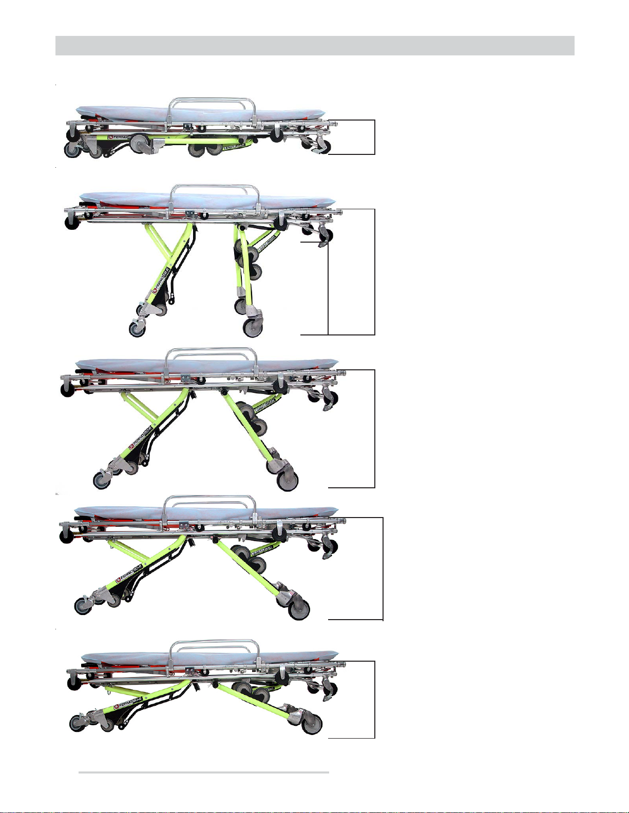
3.6 Stretcher Positions ............................................. 10
4 - Model 50-E Undercarriage ................................ 11-14
4.1 Components ........................................................ 11
4.2 Touch Bars .......................................................... 11
4.3 Quick Fix Lock .................................................. 12
4.4 Position Control Handles ................................... 13
4.5 Foot-End Caster Wheel Locks ........................... 13
4.6 Head-End Caster Swivel Locks ......................... 14
5 - Model 155-E Stretcher Top ................................ 15-18
5.1 Components ....................................................... 15
5.2 Stretcher Top Positions ...................................... 15
5.3 Changing Stretcher-Top Positions ..................... 16
5.4 Gas-Assist Backrest ........................................... 16
5.5 Side Rails ........................................................... 17
5.6 Carrying Handles - Recumbent Position ........... 17
5.7 Carrying Handles - Chair Position..................... 18
6 - Stretcher Setup.................................................... 19-23
6.1 Preparing the Stretcher for Use ......................... 19
6.2 Guidelines for Using Restraints ......................... 19
6.3 Attaching One-Piece Restraints ......................... 20
6.4 Attaching Harness Components ................... 20, 21
6.5 Adjusting Restraint Length ................................ 22
6.6 Securing the Patient ..................................... 22, 23
6.7 Unfastening the Harness .................................... 23
6.8 Removing the Restraints .................................... 23
7 - Using the Stretcher ............................................. 24-33
7.1 Before Placing the Stretcher in Service ............. 24
7.2 General Guidelines for Use ............................... 24
7.3 Attaching Stretcher Top to Undercarriage ......... 25
7.4 Removing Stretcher Top from Undercarriage ... 26
7.5 Raising/Lowering the Stretcher
With Two Operators ........................................... 27
7.6 Raising/Lowering the Stretcher
With One Operator ............................................. 28
7.7 Transferring the Patient ..................................... 29
7.8 Rolling the Stretcher .......................................... 30
7.9 Increasing the Loading Height ........................... 30
7.10 Loading the Stretcher Into an Ambulance ......... 31
7.11 Unloading the Stretcher from an Ambulance .... 32
7.12 Using Additional Help ....................................... 33
8 - Maintenance ........................................................ 34-36
8.1 Maintenance Schedule ....................................... 34
8.2 Disinfecting and Cleaning the Restraints .......... 34
8.3 Disinfecting and Cleaning the Mattress ............. 34
8.4 Disinfecting and Cleaning the Stretcher ............ 35
8.5 Waxing the Stretcher .......................................... 35
8.6 Tracker™............................................................. 35
8.7 Inspecting the Stretcher ..................................... 35
8.8 Lubricating the Stretcher ................................... 36
9 - Accessories and Related Products .......................... 37
10 - Repair Parts and Service ...................................... 38
10.1 Parts and Service - Australia .............................. 38
10.2 Parts and Service - Worldwide .......................... 38
11 - Limited Warranty .................................................. 39
12 - Ferno Customer Relations .................................... 39
Training Record............................................................. 40
Maintenance Record ..................................................... 41
PageSection PageSection

4© Ferno-Washington, Inc. 234-3257-01 December, 2004
Ferno Model 50-E
ILLUSTRATIONS
Safety and Instruction Labels ............................................ 6
Height and Strength Considerations .................................. 7
Stretcher Positions ........................................................... 10
Model 50-E Stretcher Components .................................. 11
Figure 1 - Touch Bars ....................................................... 11
Figure 2 - Undercarriage Head-End Hooks .................... 12
Figure 3 - Lock Bar (Bottom of Stretcher Top) .............. 12
Figure 4 - Engaging the Quick Fix Lock ......................... 12
Figure 5 - Head-End Control Handle (Red) .................... 13
Figure 6 - Foot-End Control Handles ............................. 13
Figure 7 - Engaging a Wheel Lock ................................. 13
Figure 8 - Caster Lock Release Lever ............................. 14
Figure 9 - Locking the Swivel Caster .............................. 14
Model 155-E Stretcher Top Components....................... 15
Stretcher Top Positions.................................................... 15
Figure 10 - Changing Stretcher Top Positions ................ 16
Figure 11 - Backrest Release Handle .............................. 16
Figure 12 - Using the Gas-Assist Backrest ..................... 16
Figure 13 - Using the Stretcher Top Side Rail ................ 17
Figure 14 - Telescoping Head-End Handles ................... 17
Figure 15 - Folding Foot-End Handles ........................... 17
Figure 16 - Chair Carrying Points ................................... 18
Figure 17 - Restraints Prepared for Use.......................... 19
Figure 18 - Patient Secured ............................................. 19
Figure 19 - Attaching a One-Piece Restraint
Through the Backrest .................................... 20
Figure 20 - Threading a One-Piece Restraint
Through the Seat Panel ................................. 20
Figure 21 - Positioning the Pelvis Strap.......................... 20
Figure 22 - Attaching the Pelvis Strap Bracket ............... 20
Figure 23 - Attaching a Brackrest Strap Bracket
to a Mounting Post ........................................ 21
Figure 24 - Fitting the Retaining Plug ............................. 21
Figure 25 - Adjusting Restraint Length ........................... 22
Figure 26 - Fitting the Harness ........................................ 22
Figure 27 - Adjusting the Shoulder Straps ...................... 22
Figure 28 - Patient Secured ............................................. 23
Figure 29 - Removing the Harness .................................. 23
Figure 30 - Attaching the Stretcher Top .......................... 25
Figure 31 - Stretcher Top Rollers
and Undercarriage Hooks ............................. 25
Figure 32 - Engaging the Quick Fix Lock ....................... 25
Figure 33 - Disengaging the Quick Fix Lock .................. 26
Figure 34 - Removing the Stretcher Top ......................... 26
Figure 35 - Raising the Stretcher..................................... 27
Figure 36 - Lowering the Stretcher ................................. 27
Figure 37 - Lowering by One Level ................................ 28
Figure 38 - Raising by One Level ................................... 28
Figure 39 - Placing Stretcher Top Near Patient .............. 29
Figure 40 - Placing Stretcher Near Patient ..................... 29
Figure 41 - Rolling the Stretcher ..................................... 30
Figure 42 - Increasing the Loading Height ..................... 30
Figure 43 - Preparing to Load the Stretcher .................... 31
Figure 44 - Head-End Legs Folded; Foot-End
Touch Bar in Contact with Bumper .............. 31
Figure 45 - Check That Foot-End Legs Lock ................. 32
Figure 46 - Check That Head-End Legs Lock ................ 32
Using Additional Help ..................................................... 33
Maintenance Table .......................................................... 34
Figure 47 - Tracker™........................................................ 35
Lubrication Diagrams ...................................................... 36
Serial Number Locations ................................................. 39

© Ferno-Washington, Inc. 234-3257-01 December, 2004 5
Ferno Model 50-E
1 - SAFETY INFORMATION
1.1 Warning
Warning notices indicate a potentially hazardous
situation which, if not avoided, could result in injury.
The following warnings appear in this manual.
1.3 Bloodborne Disease Notice
To reduce the risk of exposure to bloodborne diseases such
as HIV-1 and hepatitis when using the stretcher, follow the
disinfecting and cleaning instructions in this manual.
Safety Information
1.2 Important
Important notices emphasize important usage or
maintenance information.
Improper parts and service can cause injury.
Use only Ferno parts and Ferno-approved
service on the stretcher.
Modifying the stretcher can cause injury and
damage. Use the stretcher only as designed
by Ferno.
WARNING
!
1.4 Stretcher-Fastener Compatibility
For the purpose of the following notice, the 50-E and all
Ferno stretchers are included under the generic term, cot:
Combining different manufacturer’s products into a
“mixed-component” cot/cot fastener system can increase
the users’risk of injury and damage. Ferno-Washington,
Inc. strongly recommends that only Ferno-manufactured
cots be used in Ferno-manufactured cot fasteners, and
that only Ferno-manufactured cot fasteners be used for
securing Ferno-manufactured cots in ambulances.
ANY COMBINATION OF A FERNO COT OR COT
FASTENER WITH A NON-FERNO COT OR COT
FASTENER IS MISUSE OF THE FERNO PRODUCT.
Responsibility for the outcome of known, intentional
misuse rests squarely on the misuser.
Important
The stretcher top Safe Working Load (S.W.L.)
is less than the S.W.L. for the system of
stretcher top and undercarriage. Do not exceed
the S.W.L. limits shown in this manual.
Untrained operators can cause injury or be
injured. Permit only trained personnel to
operate the stretcher.
Improper use of the stretcher can cause injury.
Use the stretcher only for the purpose described
in this manual.
Modifying the stretcher can cause
unpredictable operation and injury. Do not alter
or modify the stretcher to fit the ambulance.
Releasing the swivel locks increases the
possibility for the stretcher to tip. Maintain
control of the stretcher at all times.
Worn or damaged restraints can fail and cause
injury. Inspect restraints regularly. Dispose of
restraints that are worn, damaged, or have been
involved in a vehicular accident.
Improper operation can cause injury. Operate
the stretcher only as described in this manual.
An unattended patient can be injured. Stay with
the patient at all times.
An unrestrained patient can fall off the stretcher
and be injured. Use restraints to secure the
patient on the stretcher.
An improperly attached stretcher top can
separate from the undercarriage and cause
injury. Attach the stretcher top only with the
head end facing the undercarriage loading end.
An unlocked undercarriage can cause injury.
Verify that each set of legs locks when
unloading the stretcher.
Helpers can cause injury. Maintain control of
the stretcher, operate the controls, and direct
all helpers.
Helpers can be injured. Show helpers where to
grasp the stretcher to avoid pinch points.
Improper maintenance can cause injury. Maintain
the stretcher only as described in this manual.
Attaching improper items to the stretcher can
cause injury. Use only Ferno-approved items on
the stretcher.
WARNING
!

6© Ferno-Washington, Inc. 234-3257-01 December, 2004
Ferno Model 50-E
1.5 Safety and Instruction Labels
Safety and instruction labels place important information from the users’ manual on the stretcher. Read and follow
label instructions. Replace worn or damaged labels immediately. New labels are available from your Ferno distributor
(page 39). The following labels are affixed to the stretcher.
Safety Information
MODEL 50-E UNDERCARRIAGE LABELS
Foot-End Control Label (1)
Head-End Control Label (1)
Pinch Point Label (2)
Backrest Control
Label (1)
Shock Position Release
Lever Label (2)
MODEL 155-E STRETCHERTOP LABELS
Identification Label - Head End (2) Identification Label - Foot End (2)
Quick Fix Lock Label (2)
Safe Working Load Information Label (1)

© Ferno-Washington, Inc. 234-3257-01 December, 2004 7
Ferno Model 50-E
2 - OPERATOR SKILLS ANDTRAINING
2.1 Skills
Operators using the stretcher need:
a working knowledge of emergency patient-
handling procedures.
the ability to assist the patient.
a complete understanding of the procedures
described in this manual.
2.3 Clearance, Height, and Strength Considerations
The Model 50-E is designed so that under normal
conditions, the operator lifts only until the rear set of
legs unfolds and locks.
However, if the ambulance is parked in a low area or on
an incline, the operator (and any helpers) may need to
lift the stretcher foot end off the ground to provide
clearance for the foot-end legs to unfold completely and
lock (see illustration above). When the legs have locked,
set the stretcher on the ground.
After the head-end legs have unfolded, test that they have
locked by pushing them gently against the ambulance
2.2 Training
Trainees need to:
follow a training program designed by their
training officer.
read this manual. For additional free users’
manuals, contact your Ferno distributor (page 39).
Operator Skills and Training
bumper. The legs should not fold. If they do, again lift
the stretcher off the ground to allow clearance for the
head-end legs to unfold completely and lock.
Be aware that supporting the weight of the stretcher,
patient and equipment requires greater strength from a
short operator than from a tall operator because a short
operator must raise his or her arms higher in relation to
the shoulders.
Note: Use additional help as needed when lifting the
weightofthe stretcher,patient,and equipment (seeUsing
Additional Help, page 33).
Untrained operators can cause injury or be
injured. Permit only trained personnel to
operate the stretcher.
WARNING
!
practice with the stretcher before using it in
regular service.
be tested on their understanding of the stretcher.
record their training information. A form is
provided on page 40.
Clearance

8© Ferno-Washington, Inc. 234-3257-01 December, 2004
Ferno Model 50-E
3.2 Vehicle Considerations
The ambulance patient compartment must have:
• A smooth, level floor large enough for the
stretcher.
• An approved, installed Ferno stretcher fastener
configured for use with the Model 50-E.
• Floor height at the specified dimension (see the
Loading Height on page 9).
If needed, modify the ambulance to fit the stretcher by
adding ramps, a folding rear step, etc. Do not alter the
stretcher or the stretcher operating procedures.
3 - ABOUTTHE STRETCHER
3.1 Description
The Model 50-E Series Easy Load Stretcher is an
emergency patient-handling device. Its components are
a Model 155-E removable stretcher top and a Model
50-E undercarriage. In this manual, the system of
stretcher top plus undercarriage will be referred to as
the “stretcher.”
The stretcher is for use by trained operators. Ferno
strongly recommends using two operators, even though
the stretcher can be operated by one trained operator.
The stretcher is designed for roll-in loading to help
reduce the risk of back injury to medical service
personnel.
About the Stretcher
STRETCHERTOP FEATURES
• Side rails
• Carrying handles
• 4 Positions (recumbent, 2 shock, and chair)
• Infinitely-adjustable gas-assist backrest
• Quick Fix lock
UNDERCARRIAGE FEATURES
• 5 Level positions with multi-level positioning (can
be locked into a different level at each end)
• Automatic head-end-leg safety lock touch bar
• Automatic foot-end-leg release touch bar
• 150 mm casters with swivel locks (head end)
• 125 mm casters with wheel locks (foot end)
• Loading wheels and intermediate loading wheels
Improper use of the stretcher can cause
injury. Use the stretcher only for the purpose
described in this manual.
WARNING
!
3.3 General Specifications
General specifications are rounded to the nearest whole
number.
• Stretcher-top heights are measured from the
ground with the stretcher top removed from the
undercarriage.
• Stretcher heights are measured from the ground
to the top of the stretcher top main frame.
• Weights do not include the mattress, restraints,
equipment brackets, or accessories.
• Loading height is measured from the ground to
the bottom of the front loading wheels.
Ferno reserves the right to change specifications
without notice.
Modifying the stretcher can cause
unpredictable operation and injury. Do not
alter or modify the stretcher to fit the
ambulance.
WARNING
!

© Ferno-Washington, Inc. 234-3257-01 December, 2004 9
Ferno Model 50-E About the Stretcher
3.4 Component Specifications
155-E STRETCHERTOP (RECUMBENT POSITION)
Length (handles extended) .......................... 2360 mm
Length (handles retracted) .......................... 1960 mm
Width ............................................................. 560 mm
Height (top of side rail) ................................. 330 mm
Height (top of mattress) ................................ 230 mm
155-E STRETCHERTOP (SEATED POSITION)
Height (seat) .................................................. 580 mm
Height (back) ............................................... 1470 mm
Depth (at seat) ............................................... 710 mm
Weight................................................................ 17 kg
Safe Working Load (S.W.L.) ........................... 159 kg
50-E UNDERCARRIAGE
Length .......................................................... 1980 mm
Width ............................................................. 560 mm
Weight................................................................ 32 kg
SYSTEM
SAFEWORKING LOAD
(System = Undercarriage
plus StretcherTop)
Length .......................................................... 1980 mm
Width ............................................................. 560 mm
Loading height ............................................... 710 mm
Height
Position A ................................................ 855 mm
Position B ................................................ 762 mm
Position C ................................................ 645 mm
Position D ................................................ 427 mm
Folded ...................................................... 175 mm
Combined Weight .............................................. 49 kg
Safe Working Load (S.W.L.) ........................... 250 kg
STRETCHERTOP
SAFEWORKING LOAD
159 kg
S.W.L.
3.5 Combined Stretcher Specifications (StretcherTop & Undercarriage)
250 kg
S.W.L.
LOAD LIMIT
LOAD LIMIT
Important
The stretcher top Safe Working Load (S.W.L.)
is less than the S.W.L. for the system of
stretcher top and undercarriage. Do not exceed
the S.W.L. limits shown in this manual.

10 © Ferno-Washington, Inc. 234-3257-01 December, 2004
Ferno Model 50-E
3.6 Stretcher Positions
About the Stretcher
FOLDED
POSITION A:
ROLLING/LOADING
POSITION B:
TRANSFER
POSITION D:
TRANSFER
POSITION C:
TRANSFER
175 mm
855 mm
762 mm
645 mm
427 mm
Loading Height
710 mm

© Ferno-Washington, Inc. 234-3257-01 December, 2004 11
Ferno Model 50-E 50-E Undercarriage
4 - MODEL 50-E UNDERCARRIAGE
4.2 Touch Bars
The undercarriage has two touch-bar mechanisms
(Figure 1) that automatically function as the stretcher
is being loaded into an ambulance.
When the operator activates the foot-end control handle
(page 13) to load the stretcher into the ambulance, the
following events occur:
• The head-end touch bar is activated when it contacts
the ambulance floor. It releases a secondary lock and
allows the head-end legs to fold.
• The foot-end touch bar is activated when it contacts
the ambulance bumper. It unlocks the foot-end legs.
For complete loading instructions, see page 31. Figure 1 - Touch Bars
Head-End
Touch Bar
Foot-End
Touch Bar
4.1 Components
Foot-End Leg
Override Handle
Loading or Foot-End
Lowering Handle
5" Swivel Wheel
with Wheel Lock (2)
6" Swivel Wheel (2)
Head-End Quick Fix
Lock Hook (4)
Swivel Lock
Release Lever
Loading
Wheel (2)
Foot-End
Touch Bar
HEAD END
FOOT END
Head-End Touch Bar
Head-End
Lowering Handle
Intermediate
Loading Wheel (4)
Intermediate
Loading Wheel (2)
Tracker

12 © Ferno-Washington, Inc. 234-3257-01 December, 2004
Ferno Model 50-E50-E Undercarriage
4.3 Quick Fix Lock
The Quick Fix lock is a system of hooks that secures the
stretcher top to the undercarriage. It is composed of:
• Undercarriage: 4 stationary hooks at the
head end (Figure 2)
• Stretcher top: 2 stationary foot-end hooks and
a lock bar with 2 hooks (Figure 3)
The six stationary hooks help hold the stretcher top on
the undercarriage. The lock bar secures the two
components together. Leave the lock bar disengaged
when the stretcher top is not on the undercarriage.
USINGTHE LOCK BAR
The lock bar is located under the stretcher top and has
two hooks that grasp the undercarriage main frame. It
is engaged by moving it across the undercarriage from
the patient left to the patient right.
OPERATOR STANDING ON PATIENT LEFT
To engage the lock bar (Figure 4):
1. Lift the lock lever (the hooks will drop down).
2. Push the lock bar hook across the stretcher.
3. Release the lock lever.
To disengage the lock bar:
1. Lift the lock lever.
2. Pull the lock bar hook toward yourself.
3. Release the lock lever (the hooks will swing up).
OPERATOR STANDING ON PATIENT RIGHT
To engage the lock bar:
1. Lift the lock lever (the hooks will drop down).
2. Pull the lock bar tab toward yourself.
3. Release the lock lever.
To disengage the lock bar:
1. Lift the lock lever.
2. Push the lock bar tab toward the stretcher center.
3. Release the lock lever (the hooks will swing up).
Figure 2 - Undercarriage Head-End Hooks
Hooks
Figure 4 - Engaging the Quick Fix Lock
Lock Lever
Hook
Figure 3 - Lock Bar (Bottom of Stretcher Top)
Lock Bar
Foot-End
Hook (2)

© Ferno-Washington, Inc. 234-3257-01 December, 2004 13
Ferno Model 50-E 50-E Undercarriage
4.4 Position Control Handles
There are three control handles for lowering the
stretcher or loading it into an ambulance. Do not use
the control handles when raising the stretcher.
• To lower the stretcher head end, use the head-
end red control handle (Figure 5).
• To load the stretcher into an ambulance, use the
foot-end red control handle.
Note:Thefoot-endred control handle must be activated
throughout the process of loading the stretcher into an
ambulance. For complete instructions, see Loading the
Stretcher Into an Ambulance, page 31.
• To lower the stretcher foot end, use both the
yellow/black override handle and the foot-end
control handle (Figure 6). The override handle
bypasses the rear touch bar mechanism. Pull it
and then pull the red control handle to lower the
foot end. See Raising/Lowering the StretcherWith
Two Operators, page 27 for complete instructions.
4.5 Foot-End Caster Wheel Locks
The foot end casters are fitted with wheel locks
designed to help keep the stretcher from rolling during
patient transfer and certain medical procedures.
Stay with the stretcher and maintain control of it at all
times. Do not use the wheel locks as a substitute for
operator control.
To engage a wheel lock, press the lock lever down with
your toe (Figure 7). To disengage, slide your toe under
the lever and lift it up.
Figure 5 - Head-End Control Handle (Red)
Figure 7 - Engaging a Wheel Lock
Figure 6 - Foot-End Control Handles
Lower/Load
Handle (Red)
Override Handle
(Yellow/Black)

14 © Ferno-Washington, Inc. 234-3257-01 December, 2004
Ferno Model 50-E50-E Undercarriage
Important
The head-end casters lock only when the
release handle is released and the trailing part
of each caster orients with the lock pin.
Figure 8 - Caster Lock Release Lever
4.6 Head-End Caster Swivel Locks
The stretcher’s head-end casters are locked by default.
In this condition, the wheels can roll (but not swivel)
giving the stretcher greater stability for rolling.
The operator unlocks the casters to allow the wheels to
swivel. This makes the stretcher more maneuverable.
Note: The risk of the stretcher tipping is greater when
the swivel casters are unlocked.
To unlock the casters: At the head end, swing the
release lever to the left and hold it in place (Figure 8).
This unlocks the casters and allows the wheels to swivel
freely. Hold the lever in this position as long as
additional maneuverability is needed.
To lock the casters: Release the release lever and roll
the stretcher toward the head end until the wheels rotate
and lock (Figure 9).
GUIDELINES FOR USE:
The swivel lock release lever is for use only when the
stretcher is in the rolling position (see Position A, page
10). Remember to:
• Lock the casters before loading the stretcher into
an ambulance so the wheels will not swivel and
interfere with loading/unloading.
• Lock the casters before lowering the stretcher. At
a lower position, shifting weight on the stretcher
can cause an unlocked front wheel to swivel
suddenly.
Releasing the swivel locks increases the
possibility for the stretcher to tip. Maintain
control of the stretcher at all times.
WARNING!
Figure 9 - Locking the Swivel Caster
Lock Pin
Swivel Caster
Lock (Metal)

© Ferno-Washington, Inc. 234-3257-01 December, 2004 15
Ferno Model 50-E
5 - MODEL 155-E STRETCHERTOP
155-E Stretcher Top
5.1 Components
Folding Foot-End
Handle (2)
Telescoping Head-End
Handle (2)
Side Rail (2)
Side Rail
Release Pin (2)
Quick Fix Lock
Release Lever (2)
Stretcher Top Position
Release Lever
Integrated Side
Rail IV Pole
(optional)
Gas-Assist
Backrest Control
Handle
5.2 Stretcher Top Positions
1 - Recumbent Position
4 - Seated Position3 - Shock Position - High
2 - Shock Position - Low
HEAD
END
FOOT
END
Chair Position
Carrying Handles

16 © Ferno-Washington, Inc. 234-3257-01 December, 2004
Ferno Model 50-E155-E Stretcher Top
5.3 Changing Stretcher-Top Positions
The stretcher-top leg section has four locking positions:
recumbent, seated, and two shock positions (see
illustrations on page 15). Position changes can be made
with the stretcher top on or off the undercarriage.
To change the stretcher-top position:
1. Standing at either side of the stretcher, push the
red release lever down and lift or lower the leg
section using the lifting strap (Figure 10).
2. When the desired position is reached, release the
release lever.
3. Raise or lower the leg section until the lock
engages.
5.4 Gas-Assist Backrest
The gas-assist backrest can be elevated to any angle
between 0º and 90º. To adjust the backrest:
1. Support the weight of the backrest and patient.
2. Lift the red control handle toward the backrest
frame and raise or lower the backrest (Figures
11 and 12).
3. Release the handle to lock the backrest.
Note: The backrest gas spring is under pressure.
Control the upward movement of the backrest so it does
not move too quickly. Figure 11 - Backrest Release Handle
Release Handle
Figure 12 - Using the Gas-Assist Backrest
Figure 10 - Changing Stretcher-Top Positions
Lifting Strap
Release
Lever

© Ferno-Washington, Inc. 234-3257-01 December, 2004 17
Ferno Model 50-E
TELESCOPING HEAD-END HANDLES
To extend: Press the detent button (Figure 14) and pull
the handle out until it locks.
To retract: Press the detent button and push the handle
in until it locks.
155-E Stretcher Top
FOLDING FOOT-END HANDLES
To extend: Swing the handle out until the lock sleeve
snaps over the hinge.
To fold: Slide the lock sleeve toward the handle grip
and fold the handle (Figure 15).
5.5 Side Rails
The side rails provide patient security and comfort.
Keep the side rails raised except during patient
transfer. To lower, pull the lock pin (Figure 13) and
swing the side rail down. To raise, swing the side rail
up until it locks.
Figure 13 - Using Stretcher-Top Side Rail
5.6 Carrying Handles - Recumbent Position
Extend and use the carrying handles to lift and carry the stretcher top when it is in the recumbent position.
Figure 15 - Folding Foot-End HandlesFigure 14 - Telescoping Head-End Handles
Detent
Button
Lock
Sleeve
Important
Do not lift the stretcher by the side rails. The
side rails are not designed for lifting. Lift the
stretcher by grasping the main frame of the
stretcher or stretcher top, following the
instructions in this manual.

18 © Ferno-Washington, Inc. 234-3257-01 December, 2004
Ferno Model 50-E155-E Stretcher Top
5.7 Carrying Handles -
Chair Position
To lift and carry the stretcher top in the chair position:
• The foot-end operator raises and grasps the
handles on the chair legs.
• The head-end operator grasps the crosstube,
(Figure 16), the stretcher-top main frame, or the
leg posts.
An optional stair chair handle kit (not supplied) is
available. See Accessories and Related Products,
page 37.
Figure 16 - Chair Carrying Points
Head-End
Operator Grasps:
• Crosstube
• Main Frame
• Leg Posts
Foot-End
Operator Grasps
Chair Handles

© Ferno-Washington, Inc. 234-3257-01 December, 2004 19
Ferno Model 50-E Setup
6 - STRETCHER SETUP
6.2 Guidelines for Using Restraints
• Three restraints must be used to properly secure
a patient: one harness restraint (torso and pelvis
straps) and two one-piece restraints. See
Accessories and Related Products, page 37 to
order restraints.
• To meet Australian crash standards, all three
restraints must be used and attached as shown in
this manual.
• Dispose of and replace restraints that are worn,
damaged, or have been involved in a vehicular
accident. Restraints that have been involved in a
vehicular accident could have hidden damage.
• Unbuckle the restraints and lay the straps out of
the way before transferring the patient (Figure 17).
• Adjust restraints to safely secure the patient
without causing discomfort or impairing
circulation (Figure 18).
• Keep restraints fastened when not in use to prevent
them from interfering with stretcher operation.
6.1 Preparing the Stretcher for Use
Attach Australian Standards-approved restraints
as shown in this section.
Put the mattress in place.
Worn or damaged restraints can fail and
cause injury. Inspect restraints regularly.
Dispose of restraints that are worn, damaged,
or have been involved in a vehicular accident.
WARNING
!
Attach any accessories that will be used with the
stretcher. Follow the instructions included with
accessories. Keep accessory instruction manuals
with this manual.
Conduct a preliminary inspection of the stretcher
(See Inspecting the Stretcher, page 35).
Figure 18 - Patient Secured
Harness
Restraint
One-Piece
Restraint
(For Chest)
One-Piece
Restraint
(For Thighs)
Figure 17 - Restraints Prepared for Use
Harness
Torso Strap
(2)
Link (2)
Harness
Pelvis Strap
One-Piece
Restraint
(For Thighs)
Harness
Cross-Strap
One-Piece
Restraint
(For Chest)

20 © Ferno-Washington, Inc. 234-3257-01 December, 2004
Ferno Model 50-ESetup
6.3 Attaching One-Piece Restraints
Weave the one-piece restraints through the backrest and
leg section as follows:
1. Unbuckle the restraints, raise the backrest and
place the leg section in the highest shock position.
2. Pass a buckle through one backrest slot from back
to front, pull it across the backrest panel and pass
it through the other slot (Figure 19).
3. Partially unzip the fabric cover on the leg section.
4. Thread a buckle through a slot in the cover, pass
it inside the cover and through the slot on the other
side (Figure 20).
5. Zip the cover closed.
6.4 Attaching Harness Components
The harness has two components: a shoulder harness
and a pelvis strap.
ATTACHTHE PELVIS STRAP
1. Position the pelvis strap on the seat panel and
make sure the straps are not twisted.
2. Hook the metal bracket to the mounting post on
the main frame. Pull the bracket to seat the post
in the bracket (Figures 21 and 22).
3. Repeat Step 2 to attach the other half of the
restraint to the post on the opposite side of the
stretcher top.
Figure 19 - Attaching a One-Piece Restraint
Through the Backrest
Figure 20 - Threading a One-Piece Restraint
Through the Seat Panel
Figure 21 - Positioning the Pelvis Strap
(Post Not
Shown)
Figure 22 - Attaching the Pelvis Strap
Bracket
Post
Table of contents
Other Ferno Medical Equipment manuals

Ferno
Ferno 175 Series Reference manual

Ferno
Ferno Ultra Care 4000 User manual

Ferno
Ferno CCT Six - M User manual

Ferno
Ferno FL1 User manual

Ferno
Ferno SCOOP EXL Stretcher Operating instructions

Ferno
Ferno Child EasyFix Manual

Ferno
Ferno Viper Stretcher User manual

Ferno
Ferno 103 User manual

Ferno
Ferno 26 Cot User manual

Ferno
Ferno PROFlexX User manual

Ferno
Ferno Pedi Mate 678 User manual

Ferno
Ferno Stretcher Series User manual

Ferno
Ferno 23 User manual

Ferno
Ferno Mondial MB64 User manual

Ferno
Ferno B-lock head immobiliser Operating instructions

Ferno
Ferno Mini Cot User manual

Ferno
Ferno 26-S User manual

Ferno
Ferno 35A-NM User manual

Ferno
Ferno 24 MAXX User manual

Ferno
Ferno 28-Z PROFlexx User manual