5 Commissioning
5.1 Automatic switching point setting: auto teach-in
Prerequisite: proximity sensor is in delivery status.
1. Mount the proximity sensor roughly in the end positionè 4.2 Mechanical.
2. Connect the proximity sensorè 4.1 Electrical.
ÄProximity sensor is automatically taught in during operation, e.g. upon
initial commissioning of the complete system.
Application notes on auto teach-in
During auto teachin, each >100ms stop of the piston within the sensing range is
output as a switching point. If the piston at this position reverses its direction of
movement and leaves the sensing range without further stops, this switching
point is saved temporarily.
If the piston stops 4x consecutively at the same position, reverses its direction of
movement and leaves the sensing range without further stops, this position is
saved as a final switching point. Auto teachin is complete.
The process described corresponds with the classic use case: proximity sensor
query at the end stop of the piston stroke or at the end stop of the customer
application.
If the piston stroke is smaller than the sensing range of the SDBTMSX, ensure
that the second reversal point of the piston is outside the sensing range during
auto teachin è Tab. 3.
Application notes on auto teach-in
Auto teachin possible:
End position A
Auto teachin possible:
End position B
Auto teachin not possible. The
switching point must be set
using the capacitive operating
key.
Tab. 3
5.2 Manual operation using capacitive operating key
The proximity sensor is parameterised once it is installed.
• Be mindful of the surface temperature of the capacitive operating key and of
the drive.
• Avoid contamination and moisture on the proximity sensor.
5.2.1 Setting the switching point
1. Move the piston into the sensing range of the proximity sensor.
2. Actuate the capacitive operating key 3 times to activate setup mode.
3. Actuate the capacitive operating key once to switch to the menu item "Set
switching point".
4. Actuate the capacitive operating key once.
ÄThe current piston position is taught in as the switching point.
5.2.2 Setting the switching point with variable switching window width
1. Move the piston into the sensing range of the proximity sensor.
2. Actuate the capacitive operating key 3 times to activate setup mode.
3. Actuate the capacitive operating key twice to switch to the menu item "Set
switching point with variable switching window width".
4. Actuate the capacitive operating key once.
ÄThe current piston position is taught in as a switching point with approx.
2mm switching window width.
Every other keystroke increases the switching window width by approx.
1mm. A max. switching window width of 15mm is possible.
5.2.3 PNP/NPN switch-over
1. Actuate the capacitive operating key 3 times to activate setup mode.
2. Actuate the capacitive operating key 3 times to switch to the menu item
"Switch over between PNP / NPN".
3. Actuate the capacitive operating key once to switch between PNP> NPN or
NPN> PNP.
5.2.4 NO/NC switch-over
1. Actuate the capacitive operating key 3 times to activate setup mode.
2. Actuate the capacitive operating key 4 times to switch to the menu item
"Switch over between NO / NC".
3. Actuate the capacitive operating key once to switch between NO> NC or
NC> NO.
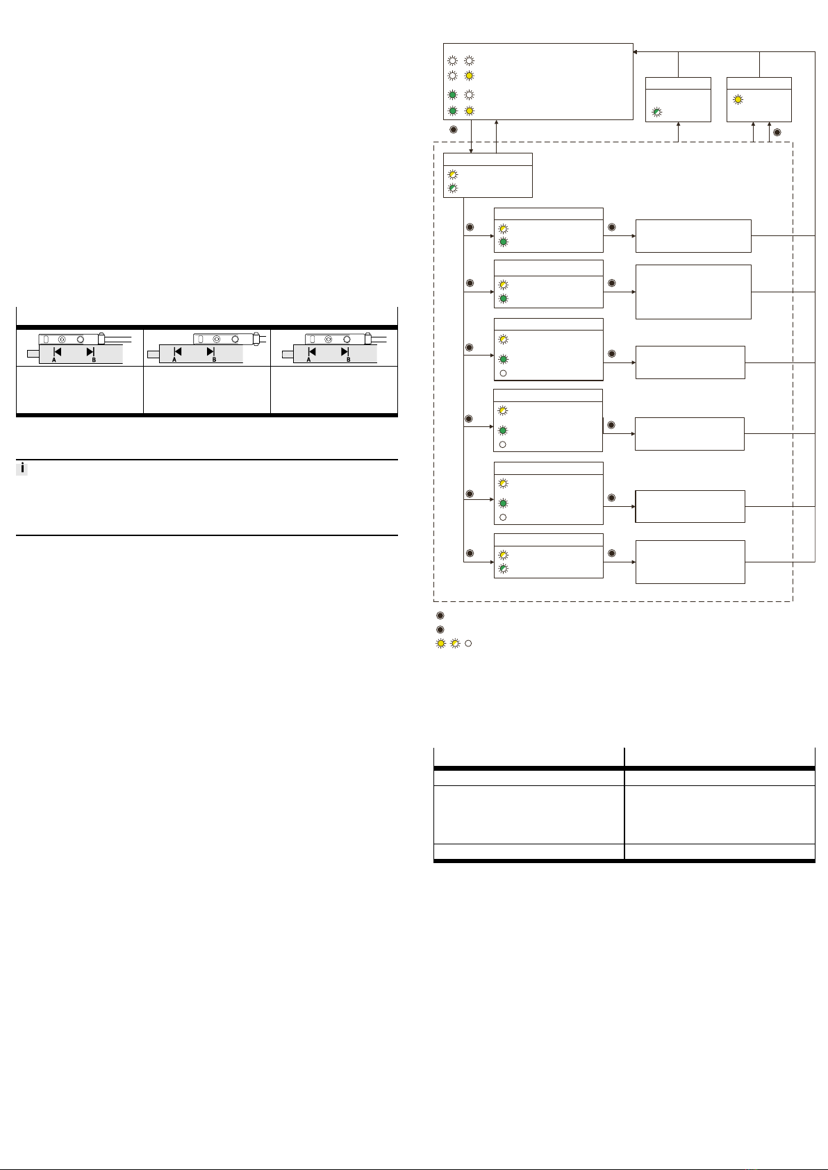
5.3 Menu structure
Green LED on & yellow LED off:
piston magnet in sensing range; no switching point
Set-up mode
Flashes yellow and
green in the form of
moving lights
Set switching point
Green ON: teach-in possible1)
Flashes yellow once, then 2 s
pause
Set switching point with variable width
of switching window
Flashes yellow 2 times, then 2 s
pause
Switch: PNP ßà NPN
Flashes yellow 3 times, then 2 s
pause
Current status: Green ON: PNP
green OFF: NPN
Reset to factory settings
Yellow + green flash
simultaneously at 2.5 Hz
3 x Number of actuations invalid
1 x
2 x
3 x
10 x
Switching point set
Width of switching window 2 mm
1 x
N x
1 x
No switching point set
PNP (SDBT-…-PU)
NPN (SDBT-…-NU)
NO
1 x
Termination
Yellow lights up
for 0.5 s
3 s
t > 60 s
Error
Green flashes at
3 Hz for 1 s
N x = press capacitive operating key (e.g.: 3 x);
Max. 1 second pause between two consecutive presses. After a 1 second pause, entry is copied.
= LED ON / LED flashes / LED OFF (e.g.: yellow LED)
1) A switching point can only be set when the green LED is ON.
When the green LED is flashing at 1.5Hz, the magnet is located in the region of the function reserve. It is not possible to set a
switching point. The function reserve is required for the safe setting of switching points in the edge region.
When the green LED is OFF, the magnet is outside the sensing range. It is not possible to set a switching point.
Switch:
PNP àNPN or:
NPN àPNP
3 s = hold the capacitive operating key pressed for at least 3 seconds
Menu: (green LED flashes when the capacitive operating key is pressed)
Both LEDs off:
Outside the sensing range; no switching point
Both LEDs on:
Piston magnet in sensing range; switching point
Green LED off & yellow LED on: cylinder switch operation:
switching point finally programmed as a teach-in value
Green ON: teach-in possible1)
Switching point set & width of switching
window + 1 mm:
N=1: 2 mm
N=2: 3 mm
…
N=14: 15 mm (max. width of switching
window)
Display: PNP / NPN
Flashes yellow 5 times, then 2 s
pause
Current status: Green ON: PNP
green OFF: NPN
5 x 1 x
Exit
Switch: NO ßà NC
Flashes yellow 4 times, then 2 s
pause
Current status: Green ON: NO
Green OFF: NC
4 x
1 x Switch:
NO àNC or:
NC àNO
Display with factory settings [NO]
Fig. 4
6 Reset to factory settings.
Parameter Factory setting
Operating mode Auto teachin
Switching output No switching point programmed
Configuration of the switching output:
– SDBT…PU: PNP
– SDBT…NU: NPN
Switching element function: NO
Variable switching window width Not programmed
Tab. 4
1. Actuate the capacitive operating key 3 times to activate setup mode.
2. Actuate the capacitive operating key 10 times to switch to the menu item
"Reset to factory settings".
3. Actuate the capacitive operating key once.
ÄProximity switch is reset to factory settings.


