manuals.online logo
Brands
  1. Home
  2. •
  3. Brands
  4. •
  5. Festo
  6. •
  7. Accessories
  8. •
  9. Festo SRAP-M-CA1 Series User manual

Festo SRAP-M-CA1 Series User manual

Sensor box
SRAP−M−CA1−...
Festo AG & Co. KG
Postfach
D−73726 Esslingen
++49/711/347−0
www.festo.com
(en) Operating instructions 745898
1006NH
Original: de
1 Operating elements and connections
12
3
4
5
6
8
9aJ
aA
aB
aC
8
7
aD
4
a
2
a
1Cover with plastic cap
2Socket head screws (M5)
3Indicator ring of the position
indicator
4Sections of the position indicator
5Shaft
6Baseplate
7Teach button
8Mounting screws
(captive)
9LED (yellow)  status display for
teach procedure
aJ Earth terminal
aA Terminal strip
aB LED (green)  power supply
indicator
aC Magnet holder
aD Cable connector (max. 2)
a = included separately
Fig.1: Design, operating elements and connections of the sensor box
2 Design
The sensor box SRAP is contained in a sturdy aluminium housing. A transparent
plastic cap in the cover allows the three−dimensional visual position indicator to be
seen (èFig.1 1). A shaft (èFig.1 5) leads outwards from the centre of the
baseplate, and is linked mechanically with the position indicator. On the sides, the
sensor box has up to two cable connectors, depending on the model (èFig.1 aD ).
The visual position indicator is comprised of sections. The sections can be put
together so as to display the flow paths of single−way or multiple−way valves
(èFig.1 3and 4).
The housing contains the device electronics and a 9−pin terminal strip for electrical
connection (èFig.1 aA ). The device electronics include an analogue sensor which
picks up the movement of the shaft via a co−rotating magnet (èFig.1 aC ) and
converts it into an analogue current signal.
The device electronics also include a microcontroller which conditions the sensor
signal so that the start and end point of the measuring range can be defined indi
vidually using a "teach" procedure.
Four captive mounting screws (èFig.1 8) in the baseplate of the sensor box are
for mounting it mechanically on quarter−turn actuators having a mechanical inter
face in accordance with VDI/VDE Guideline 3845 (hole pattern 30 x 80 [mm] ).
The sensor box SRAP is available in various designs. Position indicators can be
supplied in a range of colours and materials, and with a number of cable connector
options.
Features Type code Description
Sensor function SRAP Sensors for angular position, analogue, series P
Product design M Mainly metal
Design C Box module
Mechanical interface A1 Direct mounting, hole pattern 30 x 80 mm
Type of display Without display
yp p y
BB Blue/black 1)
GR Green/red 1)
YB Yellow/black 1)
Measuring range 270 Angle of rotation 0 ... 270°
Nominal operating voltage 1 24 V DC
Output signal A 4 to 20 mA
Electrical connection T Terminal box (terminal strip)
Valve connection No valve connection
2 With valve connection (two cable glands) 2)
Cable connection M20 With cable gland M20, metal
P20 With cable gland M20, polymer
1) Blue, green or yellow for valve open; black or red for valve closed
2) To relay the control signal for a solenoid valve through the sensor box
Fig.2:Type code of the sensor box SRAP
3 Function
The rotation of the quarter−turn actuator and valve mounted under the sensor box
is transmitted to the shaft of the sensor box. The shaft transmits the rotation to
the visual position indicator.
The visual position indication shows whether the valve is open or closed. When the
valve is open, the indicator ring (èFig.1 3) is lowered and the sections indicate
the flow path. A raised indicator ring indicates that the valve is closed.
1Indicator ring is
lowered (valve
open)
2Indicator ring is
raised (valve
closed)
Fig.3: Example  display for single−way v alves
1 2
The rotation of the shaft is evaluated with the aid of the co−rotating magnet by a
magnetically sensitive sensor element. The sensor signal is conditioned and output
as an analogue current signal. The sensor box SRAP returns an angle−proportional
output signal of 4 mA ... 20 mA within the taught measuring range.
If the end points of the defined measuring range are exceeded by up to 7.2° the
active output signal is kept constant (as a buffer to compensate for seal wear in
the process valve). If this range is exceeded (>7.2°), an output signal of 2 mA is
generated (out of range).
Two internal LEDs supply status information (visible during commissioning while
the housing cover is not in place). The green LED (èFig.1 aB ) lights up when the
operating voltage is correct. The yellow LED (èFig.1 9) supplies status informa
tion about the teaching procedure. The teaching procedure allows the end points
of the measuring range to be set individually within the availableturn angle
(0 ... 270°).
The output signal is linear between the taught end points, either rising or falling 
according to the positions of the taught end points.
The electric output signal is applied to the electrical connection (ècircuit diagram
in Fig.13). This signal can be conveyed to higher−level systems for ev aluation.
The following figures show examples of possible signal curves.
Example 1: end point 1 (MIN, 4 mA) at an angle w of 0°;
end point 2 (MAX, 20 mA) at an angle w of 90°
Fig.4:Possiblecur ve after teaching procedure  example 1
Example 2: end point 1 (MIN, 4 mA) at an angle w of 90°;
end point 2 (MAX, 20 mA) at an angle w of 0°
Fig.5:Possiblecur ve after teaching procedure  example 2
Analogue
signal
Assignment
0 mA No valid signal (e.g. wire break)
2 mA Shaft out of measuring range 1)
4 mA Taught value MIN 2) reached 4)
20 mA Taught value MAX 3) reached 4)
>4 mA
...
<20 mA
Shaft within the measuring range at the corresponding position
1) Value < MIN  position hysteresis or > MAX + position hysteresis
2) Is assigned to the current position upon the first teach signal
3) Is assigned to the current position upon the second teach signal
4) Position hysteresis (buffer): 7.2 °
Fig.6
4 Application
The sensor box SRAP is intended to be used for detecting, transmitting and dis
playing the position of quarter−turn actuators in process automation systems. The
sensor box detects the actuation position of the driven process valve.
It is suitable for use with quarter−turn actuators which actuate butterfly valves and
ball valves (process valves) with slow movements and low cycles in media−filled
pipelines.
The sensor box is optimally designed for use with Festo’s quarter−turn actuator
DFPB. It can be mounted directly on the DFPB with a suitable coupling (èFig.7 1),
without mechanical adapter bridges. It can also be used with other quarter−turn
actuators from Festo or from other manufacturers if these have a mechanical inter
face in accordance with VDI/VDE Guideline 3845 and suitable mechanical adapter
bridges are available (èwww.festo.com/catalogue).
The maximum sensing range for the sensor box is 270°.
The device is designed for use in the process industries and in industrial applica
tions.
5 Transport and storage
Ensure the following storage conditions:
 Short storage periods in cool, dry, shaded and corrosion−protected locations.
6 Requirements for product use
Fitting and commissioning is to be carried out only by qualified personnel in ac
cordance with the operating instructions.
Warning
Pinch point! Body parts can be injured by the rotating shaft.
· Vent the system before mounting or removing.
· Ensure that no one can put their hands near any moving parts.
It must not be possible to touch the shaft until the system is unpressurized.
Note
Improper handling can result in malfunctions.
· Make sure that all the instructions in this chapter are observed. The product
will then function correctly and reliably.
· Compare the maximum values specified in these operating instructions with
your actual application (e.g. currents, voltages, torques, temperatures). The
product can only be used in accordance with the relevant safety guidelines if the
maximum load limits are observed.
· All applicable national and international regulations must be complied with.
· Remove the packaging. The packing is intended for recycling (except for: oiled
paper = general waste).
· Take into consideration the ambient conditions at the location of use. Corrosive
environments reduce the service life of the product.
· Use the product only in process industries and in industrial applications, only as
intended, in its original condition without unauthorized modifications, and in
perfect technical condition. Only the conversions and modifications described in
this documentation are permitted.
· The product is not a safety component and must only be used as designated.
·Ifcommercially−availablevalves are connected, the specified limits for pres
sures, temperatures, electrical data, torques, etc. must not be exceeded.
· Please select the appropriate accessories, for example adapter bridges, coup
lings and electric cable, from our catalogue www.festo.com/catalogue.
7 Installation
Caution
Uncontrolled movements of the drive can cause damage during mounting.
· Before installing the sensor box, make sure that the compressed air and
power supply are switched off and the quarter−turn actuator is unpressurized.
· Lock out the system to prevent it being restarted.
7.1 Mechanical installation
· For use with the
DFPB, use a suitable
mechanical coupling
1. When using
other quarter−turn
actuators, you will
need suitable
adapter bridges 2
(see accessories in
ècatalogue
www.festo.com/
catalogue).
· Mount and assemble
the sensor box so
that it works in the
manner desired.
Fig.7
1
2
For mounting on quarter−turn actuators, the sensor box has a pattern of mounting
holes in accordance with VDI/VDE Guideline 3845 (ècatalogue www.festo.com/
catalogue).
The four mounting screws (èFig.1 8) are already captive−attached in the base
plate. To mount the sensor box, you must remove the housing cover (èFig.1 1)
and the 9−pin terminal strip (èFig.1 aA ).
Before mounting
1. Put the valve in one of its end positions.
2. Ensure there is no tension or pressure applied.
Mounting
1. Undo the four socket head screws on the cover (èFig.1 2).
2. Carefully lift up the cover.
3. Using a suitable tool (e.g. a pin or screwdriver), carefully press down the two red
release levers on the pin strip, one after the other. This releases the terminal
strip.
1Release levers on the
pin strip
2Screwdriver
Fig.8
1
2
1
4. Remove the terminal strip from the housing. You can now access the two mount
ing screws underneath.
5. Using a suitable tool or with the aid of the coupling, align the shaft of the sensor
box so that the shaft of the sensor box, the coupling and the shaft of the
quarter−turn actuator all intermesh in the desired way (see example in Fig.9).
1Quarter−turn actuator
(here DFPB)
2Coupling for force
transmission
3Shaft of the sensor box
4Sensor box SRAP
(view from below)
Fig.9
12
3
2
4
6. Position the sensor box on the quarter−turn actuator so that the two shafts en
gage. If necessary, use appropriate mechanical adapter bridges and couplings
(ècatalogue www.festo.com/catalogue).
7. Tighten the four mounting screws (Fig.1 8)  torque max. 5 Nm.
7.2 Adjusting the visual position indicator
You may need to adapt the visual three−dimensional position indicator to the re
quirements of your valve. To do so, you must remove the indicator ring and disas
semble the sections of the position indicator. You can then put the sections back
together according to your requirements.
Removing the indicator ring
1. Turn the indicator ring until the bottom edge of the indicator ring and the bottom
edge of the plastic cap are flush.
2. Pivot the indicator ring around 90° (see Fig.10).
3. You can now remove the indicator ring from the cover of the sensor box.
Fig.10:Removing the indicator ring
1
23
Assembling the sections
Caution
If handled improperly, the clips on the position indicator sections could break
off.
· Take care to clip the sections together without breaking off the fastening
clips.
1. Clip the sections of the visual position indicator together in such a way that the
open paths of the valve are displayed.
Fig.11: Clipping the sections of the indicator ring together
Be sure to make the centre piece (position pointer) and the indicator ring each
from sections of the same colour. One section is included separately.
Fig.12: Construction of the position indicator  examples
Mounting the position indicator
1. Insert the indicator ring back into the sensor box cover, by reversing the steps
for removal (èalso Fig.10).
2. Push the centre piece (position pointer) of the position indicator back onto the
shaft of the sensor box. Make sure the alignment is correct.
Before you put the cover of the sensor box back in place, you must carry out the
electrical installation (èsection 7.3).
After that you can put the cover of the sensor box back in place  torque
max.5Nm.
7.3 Electrical installation
Warning
Use only power units which guarantee reliable electrical isolation of the opera
ting voltage as per IEC/DIN EN60204−1.Obser ve also the general requirements
for PELV power circuits as per IEC/DIN EN 60204−1.
Caution
Installation errors can damage the electronics or cause faults.
 Use an electrical connecting cable with a nominal outside diameter of 5 to
13mm.
 Make sure that the length of the signal cable does not exceed the permissible
length of 30 m.
Totransmit analogue signals, use only screened cables with twisted pairs.
Attach the cable screening at one end to the higher−level system.
 Connect the earth connection (èFig.1 aJ) with low impedance (short cable
with large cross−sectional area) to the earth potential.
Caution
The sensor box contains electrostatically sensitive devices. The internal electro
nic components may be damaged if they are not handled correctly.
· Observe the handling specifications for electrostatically sensitive devices.
· Discharge yourself electrostatically before fitting or removing componentsin
order to protect the components against discharges of static electricity.
The electrical connection terminals are built into the device. The device must be
opened for electrical installation. To dismantle, see the steps in section 7.1.
1. If not already done, open the cover and release the terminal strip, as described
in section 7.1.
2. Route the electric cable through the cable connector.
3. Use wire end sleeves suitable for the connection and wire the terminal strip
according to the pin allocation  cable cross section max.2.5 mm³; torque max.
0.6 Nm.
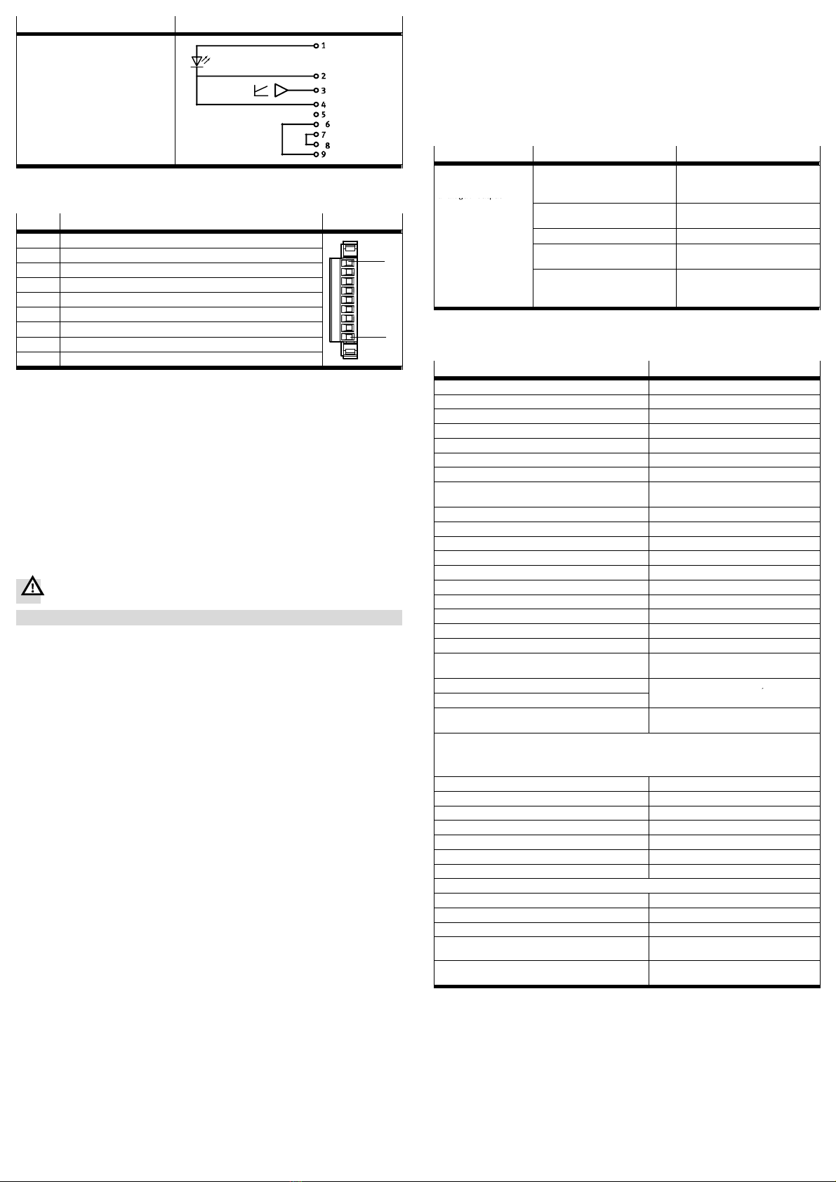
Type Circuit diagram 1)
SRAPMCA1...
1) For pin allocation, see Fig.14
Fig.13:
Pin Allocation Connection
1 Plus (+) 1)
2 Minus () 1)
9
3 (+) Out 4 ... 20 mA (sensor signal +)
9
4 () Out 4 ... 20 mA (sensor signal )
5 External Teach 2) (+24 V DC)
6 MV_IN (+) 3) 4)
7 MV_IN () 3) 4)
1
8 MV_OUT () 3) 5) 1
9 MV_OUT (+) 3) 5)
1) For the permissible operating voltage range, see section 13, Technical data
2) Input for an external teach signal, as an alternative to the teach button. For the current position to be
adopted, the teach signal (+24 V) must be present for min. 500 ms  as when pressing the teach button.
3) Can only be used with variants with valve connection SRAP−...−...−...−2..
4) For optional use to relay the control signal for the solenoid valve (MV)  infeed
5) For optional use to relay the control signal for the solenoid valve (MV)  forward relay
Fig.14
4. Connect the earth connection (èFig.1 aJ ) with low impedance (short cable
with large cross−sectional area) to the earth potential.
5. Carefully plug the terminal strip onto the pin strip. Make sure that release levers
engage properly.
6. Tighten the union nut on the cable connector. This ensures the right tensile load
capacity and IP protection class.
8 Commissioning
Warning
· Keep hands away from movingparts (see section 6).
During commissioning you define the two end positions of the actuator or process
valve corresponding to the end points of the desired measuring range. In order to
do this proceed as follows:
1. Switch on the operating voltage. The green LED lights up (power supply indica
tor èFig.1 aB ).
2. Move the quarter−turn actuator into the position which is to be adopted as the
minimum teach point (teach Min.  teach point for 4mA signal).
3. Hold down the teach button for at least about 0.5 sec or supply a corresponding
external teach signal (see Fig.14, pin 5). The current position will then be
adopted as the lower teach point, which is signalled by the yellow LED flashing.
The new teach point is effective immediately. However it is initially saved to a
volatile buffer memory which is cleared if there is a voltage drop.
4. Move the quarter−turn actuator into the position which is to be adopted as the
maximum teach point (teach Max.  teach point for 20mA signal).
5. Hold down the teach button again for at least about 0.5 sec or supply a corre
sponding external teach signal (see Fig.14, pin 5). Both teach points are then
adopted permanently as the new end points of the measuring range. This is
signalled by the yellow LED (èFig.1 9) lighting up for 3seconds. The LEDthen
goes out. That completes the teaching procedure.
6. Now, check the signalling response of the sensor box in a test run. If the end
points have been taught correctly, the sensor box will return a corresponding
signal curve (examples èFig.4and Fig.5). If an error was made, repeat
points 2. to 6.
7. When commissioning is finished, mount the cover on the sensor box  torque
max. 5 Nm.
9 Operation
· Compare the maximum values specified in these operating instructions with
your actual application (e.g. pressures, forces, torques, masses, speeds, tem
peratures). The product can only be used in accordance with the relevant safety
guidelines if the maximum load limits are observed.
10 Service and maintenance
If used as designated in the operating instructions, the device will be free of main
tenance.
· Clean the outside of the product with a soft cloth. The permitted cleaning agent
is soap suds.
11 Removal and repairs
Make sure that the following energy sources are switched off:
 Electrical power supply
 Compressed air supply
· Remove the sensor box in the reverse order of installation
(èsection 7.1).
For information about spare parts and auxiliary means èwww.festo.com/spare
parts.
12 Eliminating malfunctions
Malfunction Possible cause Remedy
Incorrect or unex
pected signal at the
analogue output
Operating voltage below the per
mitted range
Adjust the operating voltage to
within the permitted tolerance
range
analogue
output
Short circuit/overload at relevant
output
Eliminate short circuit/overload
Broken wire Replace cable
End points of the measuring range
incorrectly defined
Define the end points again using
the teaching procedure
Noisy or slow measuring signal
due to incorrect filter setting in
the PLC/IPC
Correct the filter setting in PLC/IPC
Fig.15
13 Technical data
SRAP−...−...
Based on standard VDI/VDE 3845 (NAMUR)
Mounting position Any
Protection against short circuit Yes
Measured variable Rotation angle
Measuring principle Magnetic Hall
Reverse polarity protection All electrical terminals
Setting range, angle sensing [°] 0 ... 270
Sensing range tolerance at the end posi
tions
[°] Min. 5/max. +5
Operating principle Non−contacting semiconductor output
Analogue output [mA] 4 ... 20 1)
Operating voltage range DC [V DC] 15 ... 30
Overload protection Yes
Idle current [mA] < 40
Max. load resistance at current output [] 300 (up to 500  in case of overload)
Linearity [°] ±5
Hysteresis [°] ±2
Repetition accuracy of analogue value [°] ±1
Temperature coefficient [°/K] < 0.15
Position hysteresis (buffer on the teach
points)
[°] 7.2
Interference immunity See declaration of conformity
è
Interference emission
y
èwww.festo.com
CE mark (see declaration of conformity
èwww.festo.com)
In accordance with EU EMC Directive 2)
Continuous shock resistance to DIN/IEC 68, part 2−82
Shock resistance to DIN/IEC 68, part 2−27
Vibration resistance to DIN/IEC 68, part 2−6
 When directly mounted on DFPB−... Severity level 2
 When mounted with mounting bracket Severity level 1
Protection class IP 65
Ambient temperature [°C] 20 ... +80
Surge capacity [kV] 0.8
Insulation voltage [V] 50
Degree of contamination 3
Materials information 3)
 Housing, shaft Wrought aluminium alloy
 Cover of position indicator Polycarbonate
 Seal Nitrile rubber, fluoro elastomer
 Mounting screws, toothed disc, retaining
washer Stainless steel (A2−70)
 Sensor system, position indicator
(internal) Polyacetate
1) At positions outside the defined measuring range (out of range): 2 mA
2) In residential areas, measures for radio interference suppression may be necessary.
3) For information on the resistance of materials to aggressive media èwww.festo.com.
Fig.16

Other manuals for SRAP-M-CA1 Series

1

This manual suits for next models

25

Other Festo Accessories manuals

Festo SOPA Series User manual

Festo

Festo SOPA Series User manual

Festo VMPAF-FB-PS Series User manual

Festo

Festo VMPAF-FB-PS Series User manual

Festo SOPA Series User manual

Festo

Festo SOPA Series User manual

Festo SDE5 series User manual

Festo

Festo SDE5 series User manual

Festo SDE5 series User manual

Festo

Festo SDE5 series User manual

Festo SDE1 Series User manual

Festo

Festo SDE1 Series User manual

Festo SOEL-RTD-Q50-PP-S-7L Service manual

Festo

Festo SOEL-RTD-Q50-PP-S-7L Service manual

Festo SFAH Operating and installation instructions

Festo

Festo SFAH Operating and installation instructions

Festo SFAM-62-***-T User manual

Festo

Festo SFAM-62-***-T User manual

Festo SRBC User manual

Festo

Festo SRBC User manual

Festo SOPA User manual

Festo

Festo SOPA User manual

Festo SRBP-M-CA1 series User manual

Festo

Festo SRBP-M-CA1 series User manual

Festo Sorting Station Inline User manual

Festo

Festo Sorting Station Inline User manual

Festo NEBU-M12W8-K N-LE8 Series User manual

Festo

Festo NEBU-M12W8-K N-LE8 Series User manual

Festo SPAU User manual

Festo

Festo SPAU User manual

Festo SPAN-B Series User manual

Festo

Festo SPAN-B Series User manual

Festo SPAW series User manual

Festo

Festo SPAW series User manual

Festo SFE3 Series User manual

Festo

Festo SFE3 Series User manual

Festo SFAB User manual

Festo

Festo SFAB User manual

Festo SRBG User manual

Festo

Festo SRBG User manual

Festo Span Series User manual

Festo

Festo Span Series User manual

Festo MS6-SFE-F5-AGD Series User manual

Festo

Festo MS6-SFE-F5-AGD Series User manual

Festo VMPA-FB-PS Series User manual

Festo

Festo VMPA-FB-PS Series User manual

Festo SDE3 series User manual

Festo

Festo SDE3 series User manual

Popular Accessories manuals by other brands

Dytran 3089A operating guide

Dytran

Dytran 3089A operating guide

Homelite 18987 instruction sheet

Homelite

Homelite 18987 instruction sheet

Flarion RadioRouter installation guide

Flarion

Flarion RadioRouter installation guide

Philips CPWBS154 Quick start quide

Philips

Philips CPWBS154 Quick start quide

On Point Products Inflatable Sport Boards SB.10.6 Owner's operating manual & safety information

On Point Products

On Point Products Inflatable Sport Boards SB.10.6 Owner's operating manual & safety information

Cobra 5452 installation manual

Cobra

Cobra 5452 installation manual

Edge Technologies SENSA.IO SENSA.TEMP 613-00003 instruction manual

Edge Technologies

Edge Technologies SENSA.IO SENSA.TEMP 613-00003 instruction manual

Roland TRI-Capture owner's manual

Roland

Roland TRI-Capture owner's manual

Tait TB9100 Installation and operation manual

Tait

Tait TB9100 Installation and operation manual

Hipcam Doorbell manual

Hipcam

Hipcam Doorbell manual

Ellia REFRESH ARM-560 quick start guide

Ellia

Ellia REFRESH ARM-560 quick start guide

SwitchDoc Labs WeatherSense Assembly and Test Manual

SwitchDoc Labs

SwitchDoc Labs WeatherSense Assembly and Test Manual

Advaning SG Series owner's manual

Advaning

Advaning SG Series owner's manual

AGI WESTFIELD 1500 Series Operator's manual

AGI

AGI WESTFIELD 1500 Series Operator's manual

Matchmaster 34MM-HDS2 instruction manual

Matchmaster

Matchmaster 34MM-HDS2 instruction manual

Smanos DS2300 user manual

Smanos

Smanos DS2300 user manual

IFM Electronic Efector160 LK3 operating instructions

IFM Electronic

IFM Electronic Efector160 LK3 operating instructions

Qel QTS-1710 SERIES Installation, operation and maintenance manual

Qel

Qel QTS-1710 SERIES Installation, operation and maintenance manual

manuals.online logo
manuals.online logoBrands
  • About & Mission
  • Contact us
  • Privacy Policy
  • Terms and Conditions

Copyright 2025 Manuals.Online. All Rights Reserved.