manuals.online logo
Brands
  1. Home
  2. •
  3. Brands
  4. •
  5. Festo
  6. •
  7. Accessories
  8. •
  9. Festo SDAT-MHS User manual

Festo SDAT-MHS User manual

Position sensor
SDAT-MHS
Festo SE & Co. KG
Ruiter Straße 82
73734 Esslingen
Germany
+49 711 347-0
www.festo.com
Operating instructions
(Translation of the original instructions)
8080039
2017-11e
[8080041]
Position sensor English...............................................
1 About this document
This document describes the use of the above-mentioned product.
For detailed specifications on the product, a complete description, the software
for the device (IODD) and the declaration of conformity
èwww.festo.com.
For all available product documentation èwww.festo.com/pk
2 Safety
2.1 General safety information
 Only use the product in its original condition without unauthorised modifications.
 Avoid having magnetic bodies near the position sensor. These could influence
the magnetic field and thereby the behaviour of the sensor.
 This product can generate high frequency interference, which may make it ne
cessary to implement interference suppression measures in residential areas.
 Installation and commissioning only by qualified personnel and in accordance
with the operating instructions.
2.2 Intended use
The position transmitter SDAT-MHS is intended for contactless detection of
the piston position of magnetic-sensing drives and grippers. It is appropriate
for use with with Festo drives with T-slot (profile slot 8) as well as round cylinders
and tie-rod cylinders with mounting kits.
 Use the SDAT-MHS only for the suitable drives and grippers from Festo
èwww.festo.com/catalogue.
2.3 Range of application and certification
The information in this section, in combination with the UL marking on the product,
must be observed in order for there to be compliance with the certification condi
tions of Underwriters Laboratories Inc. (UL) for USA and Canada. Observe the fol
lowing English-language remarks from UL:
UL approval information
Product category code NRKH, NRKH7
File number E232949
Considered standards UL 60947-1 and UL 60947-5-2, C22.2 No. 14-13
UL mark
Product category
Control Number
Ind. Cont. EQ.
(Industrial Control Equipment)
2MD1
Only for connection to an NEC Class 2 supply.
Raccorder Uniquement a un circuit de Classe 2.
This device is intended to be used with a Class 2 power source or Class 2 trans
former in accordance with UL1310 or UL1585.
As an alternative, an LV/C (Limited Voltage/Current) power source with one of
the following properties can be used:
– This device shall be used with a suitable isolating source such that the
maximum open circuit voltage potential available to the product is not more
than 30 V DC and the current is limited to a value not exceeding 8 amperes
measured after 1 minute of operation.
– This device shall be used with a suitable isolating source in conjunction with
a fuse in accordance with UL248. The fuse shall be rated max. 3.3 A and
be installed in the 30 V DC power supply to the device in order to limit
the available current.
Note that, when more than one power supply or isolating device is used,
connection in parallel is not permitted.
Electrical and environmental ratings
Input voltage Max. 30 V DC, Class 2
Input current 160 mA / max. 4.8 W
Analog output 4 … 20 mA
Transistor output max. 30 V DC, 100 mA G.P.
Maximum ambient temperature 70 °C / 158 °F
Enclosure type rating Type 1
3 Service
Contact your regional Festo contact person if you have technical questions
èwww.festo.com.
4 Accessories
Accessories èwww.festo.com/catalogue
5 Product overview
5.1 Function
The position transmitter SDAT-MHS records the magnetic field of the piston
magnet and continuously senses the piston movement in the sensing range.
Available output signals include:
– Analogue current signal (4 … 20 mA)
– Programmable switching output (24 V)
– IO-Link communication mode
5.2 Configuration
1
2
3
2
4
5
6
7
1Connecting cables
2Mounting screw
3Plug M8, rotatable
4Red LED: status display
5Green LED: ready status display
6Yellow LED: switching status
display
7Operating key
Fig. 1
6 Mounting and installation
Warning
Risk of injury due to electric shock.
Injury caused by electric shock, damage to machine and to system
 For the electric power supply, use only PELV circuits that ensure a reliable
electric disconnection from the mains network.
 Observe IEC 60204-1/EN 60204-1.
 Switched-mode power supplies are permitted, provided that they ensure
reliable separation in accordance with EN 60950/VDE 0805.
6.1 Circuit diagram and pin allocation
Fig. 2
Pin Allocation
1Operating voltage +24 V DC M8x1, 4-pin
2Switching output 2
30 V
4Switching output 1
Fig. 3
6.2 Installation
1
2
3
0.5 Nm
ß1.5
0.3 Nm
1Internal hexagon
socket key
2Mounting screw
3T-slot (profile slot 8)
Fig. 4
1. Insert the SDAT-MHS into the T-slot of the drive.
2. Move the piston into an end position of the application.
3. Push the SDAT-MHS in the direction of the piston until the red LED goes out.
4. Tighten the mounting screws hand-tight.
7 Commissioning
1. Switch on the operating voltage.
èThe LEDs illuminate (dependent on the piston position).
èThe device is ready for operation.
Parameter Factory setting
Switching function None
Switching logic Normally open (NO)
Scaling Total sensing range
Fig. 5
IO-Link
The IO-Link function cannot be set via the operating keys on the device. All settings
for set-up, commissioning and parameterisation are made in the higher-level con
troller of the IO-Link master.
Analogue output function
The analogue output provides a displacement-proportional output signal
4…20 mA in the sensing range of the piston stroke.
OB C
20 mA
4 mA
2 mA
0 mm x mm
x = Maximum length of the sensing range (type-dependent)
Fig. 6
Signal Description Range
0 mA IO-Link operation.
Error (e.g. broken cable, parameter error).
2 mA Piston outside of the sensing range after the operating
voltage is switched on.
A, C
4 mA The piston has left the sensing range in the direction of
the falling output current.
A
> 4 mA … < 20 mA Piston within the sensing range. B
20 mA The piston has left the sensing range in the direction of
the rising output current.
C
Fig. 7
Note
With active IO-Link communication, the analogue output is switched off (output
current = 0 mA).
8 Operation
8.1 Magnetic direction detection and correction
At initial start-up or after a reset to factory settings, the position sensor emits
signals directly using the currently detected magnetic direction.
The magnetic direction detection and, with it, the signal curve are corrected during
ongoing operation when the following cases occur:
– The position sensor was placed in operation in a position where a correct mag
netic direction detection was not possible (e.g. due to ferromagnetic materials
near the sensor or within the drive or gripper).
– The position sensor was turned 180° in the slot after the magnetic direction was
recognised as stable.
Note
Brief incorrect signals at the sensor output can occur if automatic correction of
the magnetic direction detection is required
èChap. 9.2.
8.2 Status signals in normal operation
LED indicator Description
Yellow Green Red
Ready status:
– Analogue output function or switching output operating
mode
– Piston within the sensing range
Green LED illuminated
Yellow: any, Red: off
Ready status:
– IO-Link operating mode
Green LED flashing at 1 Hz
Ready status:
– Switching output switched
– Piston in the range of a programmed function
Yellow and green LEDs light up
Status display:
– Operating key blocked
Green LED flashes 3 seconds at
3 Hz while the operating key
is pressed
Status display:
– Piston outside the sensing range
Red LED illuminated
Fig. 8
8.3 Analogue output and switching function operation
Yellow OFF
1 x flash briefly / 2 s
Red OFF if in range 1)
Display configuration: cyclical flash signals in the sequence green-yellow-red
SIO operation
Switching output status
ON
ON, if OoR
3 x Key combination
invalid
Switching function: none
Switching logic: normally open (NO)
Scaling: total sensing range
Abort
Yellow +
Green ON for 0.5 s
Errors
Yellow OFF
Green OFF
Red flash 3 Hz
3 s
t > 60 s
From each
status in
the diagram
1 x = Press operating key (e.g.: 1 x)
= LED illuminated / LED flashing / LED OFF (e.g.: green LED)
Set-up mode
Yellow +
Green flashing in common mode
ON, if OoR
Window comparator Teach point 1 Teach point 2
Cylinder switch function Teach point
Hysteresis comparator Teach point 1 Teach point 2
Switching logic NC/NO Inverting NO or NC
Scaling Teach point 1 (4 mA) Teach point 2 (20 mA)
Switching logic: 1 x - normally closed (NC), 2 x - normally open (NO)
Function: 0 x - deactivated, 1 x - window comparator, 2 x - cylinder switch function, 3 x - hysteresis comparator
Scaling: 1 x - user-configured, 2 x - total sensing range
Yellow OFF
2 x flash briefly / 2 s
Red OFF if in range 1)
Yellow OFF
3 x flash briefly / 2 s
Red OFF if in range 1)
ON if NC / OFF if NO
4 x flash briefly / 2 s
Red OFF if in range 1)
Yellow OFF
5 x flash briefly / 2 s
Red OFF if in range 1)
Flashes
5 x flash briefly / 2 s
Red OFF if in range 1)
Flashes
3 x flash briefly / 2 s
Red OFF if in range 1)
Flashes
1 x flash briefly / 2 s
Red OFF if in range 1)
Reset
Yellow + green + red flash
With 1 Hz in common mode
Factory setting
1 x
2 x
3 x
4 x
5 x
6 x
10 x
1 x 1 x
1 x
1 x 1 x
1 x
1 x 1 x
1 x
1) = Teaching of a position out-of-range (OoR) causes the red LED to flash until the magnet is back in the sensing range (in range).
9 Fault clearance
9.1 Diagnostics via LED
LED indicator Possible cause Remedy
Yellow Green Red
Voltage supply defective – Secure the power supply.
All LEDs off Connecting cable defective – Replace the connecting cable.
Device defective – Replace device.
Sensor defective – Switch power supply on/off.
– Replace device.
Red LED flashing
Short circuit/overload at
the switching output
– Eliminate short circuit/
overload.
Yellow LED flashing at 3 Hz Parameter error – Reset device to its factory
setting.
Communication error in
the IO-Link mode
– Check IO-Link master.
– Restart communication.
– Check C/Q line.
Yellow LED flashing at 3 Hz
Green LED flashing at 1 Hz
Fig. 9
Note
If the device detects an error during the IO-Link operation, a status signal is
emitted on the IO-Link master. The IO-Link output is not blocked.
9.2 General malfunctions
Malfunction Possible cause Remedy
Incorrect or unexpected sig
nals at the analogue output or
in the IO-Link process data
Inappropriate drive Use an appropriate drive.
Device defective Replace device.
No operating voltage or
impermissible operating
voltage
Comply with operating voltage
range.
Short circuit or overload at
the output
Eliminate short circuit/
overload.
Magnetic objects in close
proximity to the position
transmitter
Prevent magnetic objects
being in close proximity.
Sensor/drive rotated by 180°
after initial start-up
Reset to factory settings
(using the operating key or via
IO-Link).
Incorrect or unexpected
signals during initial start-up
on grippers or in top elements
which are partly ferromagnetic
At initial start-up, move grip
per jaws or pistons within
the sensing range (e.g. at both
end positions)
Switching output does not
switch corresponding to
the settings
Short circuit or overload at
the output
Eliminate short circuit/
overload.
Device defective Replace device.
Settings cannot be edited Access protection active Release key (only possible via
IO-Link).
Fig. 10
10 Disassembly
1. Switch off operating voltage.
2. Separate the connections from the SDAT-MHS.
3. Remove the mounting screws.
4. Take the SDAT-MHS out of the T-slot of the drive.
11 Technical data
SDAT-MHS
Certification certificate RCM, c UL us - Listed (OL)
CE marking In accordance with EU EMC Directive
Note on materials RoHS-compliant, halogen-free
Sensing range
(type-dependent)
[mm] 0  50 / 0  80 / 0  100 / 0  125 / 0  160
Typical sampling interval [ms] 1
Max. speed of travel [m/s] 2
Path resolution [mm] 0.05
Switching output PNP
Repetition accuracy
switching point
[mm] 0.1
Analogue output [mA] 4  20
Sensitivity (type-dependent) [mA/mm] 0.32/0.2/0.16/0.128/0.1
Typical linearity error [mm] ± 0.25
Repetition accuracy
analogue output
[mm] 0.1
Max. load resistance
current output
[Ω] 500
Operating voltage DC [V] 15  30
Typical signal running time [ms] < 2
Cable length [m] 0.3
Nominal conductor cross section [mm2]0.1
Max. tightening torque [Nm] 0.5
Information on materials - housing PA-reinforced, polyester, high-alloy stainless
steel, nickel-plated brass
Ambient temperature [°C] –25  +70
Ambient temperature
flexible cable
[°C] –20  +70
Degree of protection
(in accordance with EN 60529)
IP65/IP68
(condition IP68: test duration 24 h)
Fig. 11
IO-Link
Protocol version Device V1.1
Profiles Smart Sensor Profile
Function classes 0x8000, 0x8001, 0x8002, 0x8003, 0x8004
Communication mode COM3 (230.4 kBaud)
Process data length IN 2 bytes
Port class A, 4-pin
Fig. 12

Other manuals for SDAT-MHS

2

Other Festo Accessories manuals

Festo VMPAF-FB-PS Series User manual

Festo

Festo VMPAF-FB-PS Series User manual

Festo SDE5 series User manual

Festo

Festo SDE5 series User manual

Festo Span Series User manual

Festo

Festo Span Series User manual

Festo SFAB Parts list manual

Festo

Festo SFAB Parts list manual

Festo SPAE User manual

Festo

Festo SPAE User manual

Festo NECA-S1G9-P9-MP3-SA User manual

Festo

Festo NECA-S1G9-P9-MP3-SA User manual

Festo SOPA Series User manual

Festo

Festo SOPA Series User manual

Festo SRAP-M-CA1 Series User manual

Festo

Festo SRAP-M-CA1 Series User manual

Festo SOPA User manual

Festo

Festo SOPA User manual

Festo SRBG User manual

Festo

Festo SRBG User manual

Festo VN Series User manual

Festo

Festo VN Series User manual

Festo PEV-1/4A Series User manual

Festo

Festo PEV-1/4A Series User manual

Festo HMP-...-SL Series User manual

Festo

Festo HMP-...-SL Series User manual

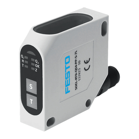
Festo SOEC-RT-Q50-PS-S-7L User manual

Festo

Festo SOEC-RT-Q50-PS-S-7L User manual

Festo ASLR-D-L1 User manual

Festo

Festo ASLR-D-L1 User manual

Festo MS6-SFE-F5-AGD Series User manual

Festo

Festo MS6-SFE-F5-AGD Series User manual

Festo SFAH Parts list manual

Festo

Festo SFAH Parts list manual

Festo SFAB-PNLK Series User manual

Festo

Festo SFAB-PNLK Series User manual

Festo SKDA-0.8-AB User manual

Festo

Festo SKDA-0.8-AB User manual

Festo SDBT-MSX Parts list manual

Festo

Festo SDBT-MSX Parts list manual

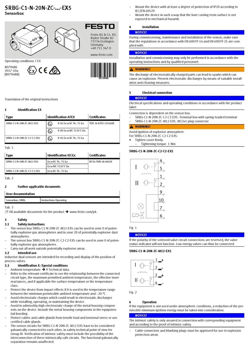
Festo Sensorbox SRBG-C1-N-20N-ZC-M12-EX5 Instruction manual

Festo

Festo Sensorbox SRBG-C1-N-20N-ZC-M12-EX5 Instruction manual

Festo AS-i Series Parts list manual

Festo

Festo AS-i Series Parts list manual

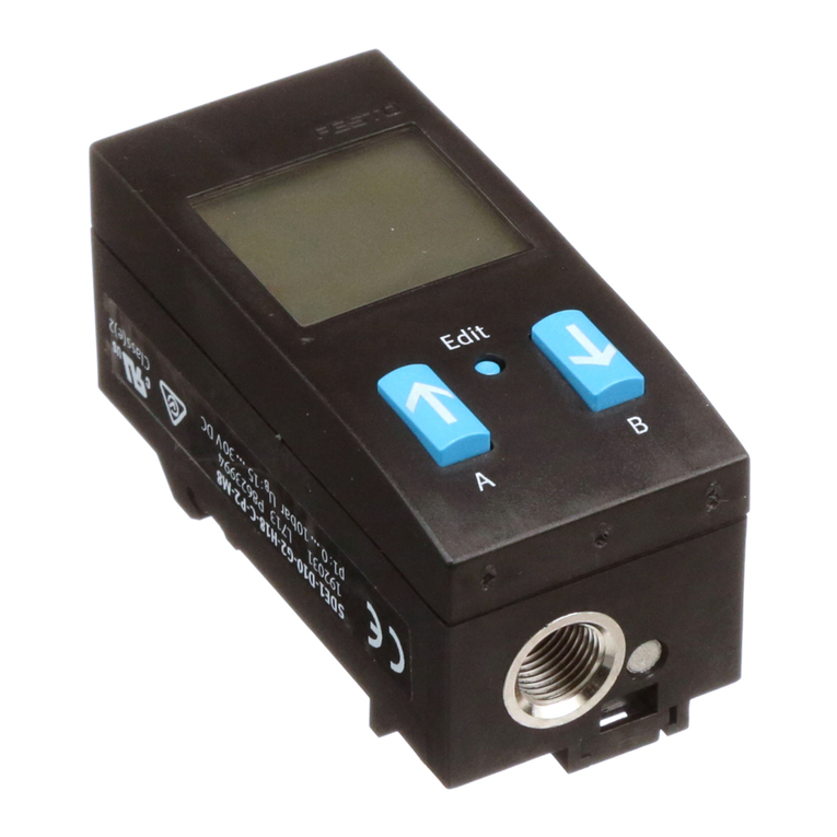
Festo SDE1 Series User manual

Festo

Festo SDE1 Series User manual

Festo SDE5 series Parts list manual

Festo

Festo SDE5 series Parts list manual

Popular Accessories manuals by other brands

Clearaudio Concept user manual

Clearaudio

Clearaudio Concept user manual

PRESONUS AudioBox iTwo Series HOOK-UP GUIDE

PRESONUS

PRESONUS AudioBox iTwo Series HOOK-UP GUIDE

Manitowoc K00044 installation instructions

Manitowoc

Manitowoc K00044 installation instructions

Hytronik HMW21 Installation and instruction manual

Hytronik

Hytronik HMW21 Installation and instruction manual

Orno OR-CR-231 Instruction

Orno

Orno OR-CR-231 Instruction

Gifas-electric 1970W user manual

Gifas-electric

Gifas-electric 1970W user manual

Honeywell Home DC917 Series manual

Honeywell Home

Honeywell Home DC917 Series manual

Galeo SYRMA Instructions for use

Galeo

Galeo SYRMA Instructions for use

OmieLife OMIEBOX user manual

OmieLife

OmieLife OMIEBOX user manual

GE Security 60-742-95R installaiton instructions

GE Security

GE Security 60-742-95R installaiton instructions

Byron Home Easy HE-202 installation instructions

Byron

Byron Home Easy HE-202 installation instructions

Tascam US-122 Application guide

Tascam

Tascam US-122 Application guide

Rinstrum R320 Reference manual

Rinstrum

Rinstrum R320 Reference manual

Stuart SI500 instruction manual

Stuart

Stuart SI500 instruction manual

Mound Yeti Mound Yeti 2 Assembly instructions and owner's manual

Mound Yeti

Mound Yeti Mound Yeti 2 Assembly instructions and owner's manual

NATURE & DECOUVERTES 60158450 manual

NATURE & DECOUVERTES

NATURE & DECOUVERTES 60158450 manual

CAME MR8534 manual

CAME

CAME MR8534 manual

Dometic SC Series operating manual

Dometic

Dometic SC Series operating manual

manuals.online logo
manuals.online logoBrands
  • About & Mission
  • Contact us
  • Privacy Policy
  • Terms and Conditions

Copyright 2025 Manuals.Online. All Rights Reserved.