Fault description Cause Remedy
In case of air consumption
measurement: measured value
is flashing
Measuring range end value has
been exceeded at least once.
Specified accuracy can there
fore probably not be main
tained.
Make sure that the end value of
the measuring range is not
exceeded.
Outputs do not switch corres
ponding to the setting
Short circuit or overload at cor
responding output
Rectify short circuit/overload.
Settings cannot be edited
(Lock)
Access protection active Enter the security code.
O.FLO Measurement range exceeded
(displayed in RUN mode)
Check operating conditions.
Er1, Er2, Er3 Device faulty Replace device.
Er9 Measurement range undershot
(displayed in SHOW mode)
Check operating conditions.
Er10 Measurement range exceeded
(displayed in SHOW mode)
Check operating conditions.
Er17 Undervoltage Maintain operating voltage.
Check electrical wiring
Tab. 11
14 Disposal
ENVIRONMENT!
Send the packaging and product for environmentally sound recycling in accord
ance with the current regulations èwww.festo.com/sp.
15 Technical data
SFAB -10U -50U -200U -600U -1000U
General
Approval CTick, c UL us Recognized (OL)
CE marking (declaration of conformity
èwww.festo.com/sp)
In accordance with EU EMC Directive
In accordance with EU RoHS Directive
SFAB...EX2: in accordance with EU Explosion Protec
tion Directive (ATEX)
Measured variable Flow rate, consumption
Flow direction Unidirectional P1 è P2
Measuring principle Thermal
Flow measuring range [l/min] 0.1…10 0.5…50 2…200 6…600 10…
1000
Operating pressure [bar] 0…10
Operating pressure [kPa] 0…1000
Nominal pressure [kPa] 600
Pressure drop [kPa] < 10
Ambient temperature [°C] 0…50
Temperature of medium [°C] 0…50
Nominal temperature [°C] 23
Compressed air to
ISO85731:2010
[6:4:4]
Compressed air to
ISO85731:2010 [7:4:4]
Operating medium
Nitrogen
Output general1)2)
Precision of zero point3) [% FS] ±0.3
Accuracy of margin3) [% FS] ±3
Repetition accuracy of zero
point
[% FS] ±0.2
Repetition accuracy of mar
gin
[% FS] ±0.8
Temperature coefficient of
margin
[% FS/K] ≤ 0.1
Pressuredependent margin [% FS/
100kPa]
±0.5
Switching output
Switching output 2x PNP or 2x NPN, adjustable
Switching function Window comparator or threshold value comparator,
adjustable
Switching element function N/C or N/O contact, adjustable
Max. output current [mA] 100
Voltage drop [V] Max. 1.5
Switchon time Adjustable (factory setting: approx. 80 ms)
Switchoff time Adjustable (factory setting: approx. 80 ms)
Inductive protective circuit Adapted to MZ, MY, ME coils
Analogue output
Characteristic flow rate curve [l/min] 0…10 0…50 0…200 0…600 0… 1000
Output characteristic curve
for current
[mA] 4…20
SFAB -10U -50U -200U -600U -1000U
Max. load resistance of cur
rent output
[Ω] 500
Min. load resistance of
voltage output
[kΩ] 10
Rise time [ms] Adjustable:
15, 30, 60 (factory setting), 125, 250, 500, 999
Output, additional data
Short circuit current rating Yes
Overload protection Present
Electronics
Operating voltage range [VDC] 15…30
Reverse polarity protection For all electrical connections
Electromechanics
Electrical connection Straight plug, M12x1, 5pin
Max. connecting cable length [m] < 10
Mechanics
Mounting position Any
Product weight [g] 160
Note on materials, housing Reinforced polyamide, polycarbonate
Display/operation
Display type Illuminated LCD, blue
Displayable units l/min, scf, scfm, l, m#, scf, l/h l/min, scf, scfm, l, m#
Setting range for flow rate
threshold value
1%FS…100%FS
Setting range for consump
tion impulse threshold value
[l] 0.1…
1999.9
0.2…
1999.9
1…
1999.9
2…
1999.9
3…
1999.9
[m#] 0.01…199.99 0.1…
1999.9
1…
19999
[scf] 0.01…199.99 0.03…
199.99
0.1…999.9
Hysteresis setting range 0%FS…90%FS
Immissions/emissions
Storage temperature [°C] –20…+80
Degree of protection IP65
Protection class III
1) Accuracy at nominal conditions (6 bar, 23 °C and horizontal mounting position)
2) % FS = % of the flow range end value (full scale)
3) The precision of the zero point and precision of the spread together correspond to the precision of the flow
rate: precision of flow rate = ± (0.3% FS + 3% of measured value). % o.m.v. = % of the measured value
Tab. 12 Technical data
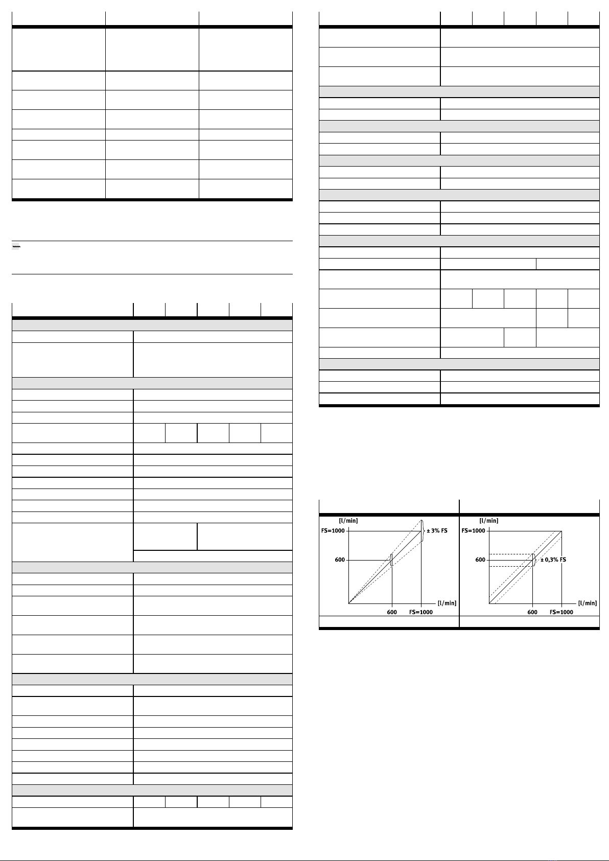
16 Examples for calculating the maximum error of the display
– Flow rate measuring range: 10…1000l/min (FS = 1000)
– Measured value: 600l/min
Range error (e.g. ±3 %FS) Zero point error
Tab. 13
Clamping error and zero point error
The range error is proportional to the measured value. At 600 l/min, the span
error is 3 % of the measured value = 18 l/min.
The zero point error is independent of the measured value. It is 0.3 %FS = 3 l/min.
Display error with nominal conditions (6 bar, 23°C):
The display error at nominal conditions is the result of adding the range and zero
error. The actual flow rate is in the range of 600 ± (18+3)l/min = 600 ± 21l/min.
Display error under different nominal conditions (e.g. 8 bar, 40°C):
Temperature and pressure errors are range errors. The temperature error at 40 °C
is ±0.1 %FS/K x 17 K = ±1.7 % of the measured value = ±10.2 l/min.
The pressure error at 8 bar is
±0.5 %FS/bar x 2 bar = ±1 % of the measured value = ±6 l/min.
The error of the display at deviating nominal conditions results from the addition
of all error values (span, zero point, temperature, pressure). The actual flow rate
is therefore in the range of 600 ± (18+3+10.2+6)l/min = 600 ± 37.2l/min.
17 Range of application and certifications
Certain configurations of the product have been certified by Underwriters Laborat
ories Inc. (UL) for the USA and Canada. These configurations bear the following
mark: