manuals.online logo
Brands
  1. Home
  2. •
  3. Brands
  4. •
  5. Festo
  6. •
  7. Control Unit
  8. •
  9. Festo VPCF-6-L-8 Series User manual

Festo VPCF-6-L-8 Series User manual

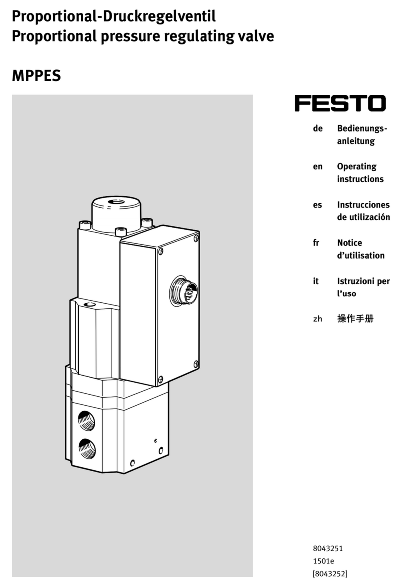
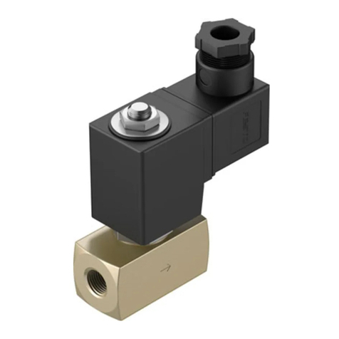
Proportional flow control valve
VPCF-6-L-8-...
Festo AG & Co. KG
Postfach
73726 Esslingen
Germany
+49 711 347-0
www.festo.com
Operating instructions 8066867
1611a
[8066869]
Original: de
Proportional flow control valve VPCF-6-L-8... English.......................
1 Safety
1.1 Use for intended purpose
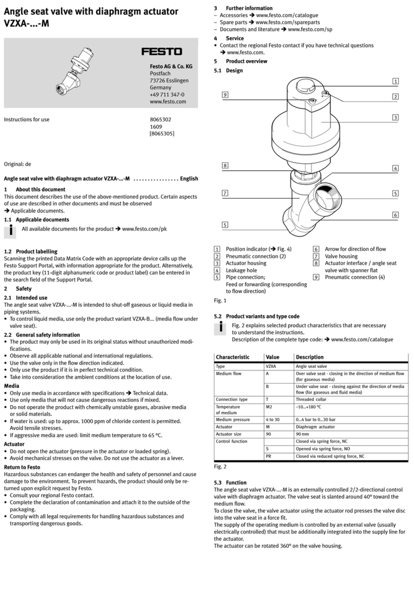
The proportional flow control valve VPCF-6-L-8-... is intended for regulation of a
flow proportional to a specified setpoint value.
The flow control valve is intended for use in an industrial environment. Outside of
industrial environments, e.g. in commercial and mixed-residential areas, actions to
suppress interference may have to be taken.
1.2 Safety instructions
 Use the flow control valve only in its original status without unauthorised modi
fications.
 Use the flow control valve only in an excellent technical status.
 Comply with all applicable national and international regulations.
 Comply with specified limits (èChapter 12, Technical data).
 Take into consideration the ambient conditions at the location of use.
1.3 Training of skilled personnel
Only qualified personnel may perform installation, commissioning, maintenance
and disassembly of the flow control valve. The qualified personnel must be familiar
with installation and operation of electrical and pneumatic control systems.
2 Structure
2
45
1
6
7
8
9
7
aJ
aA
3
6
1Electrical connection, plug M12
2Service interface, sealed with cover
cap (only for Festo service staff)
3Air port (2)
4Threaded holes M5 (10 mm deep)
for mounting of the flow control
valve, èFig. 6
5Hole for earth connection (FE),
èFig. 6
6Through-holes for mounting the
flow control valve
7Threaded holes M5 (10 mm deep)
for mounting of the flow control
valve
8Exhaust air port (3)
9Hole for earth connection (FE)
aJ Compressed air port (1)
aA LEDs
Fig. 1
3 Product variants
Characteristic Type code Description
Basic function VPCF Propor tional flow control valve
Nominal width 66 mm
Valve type LIn-line valve
Valve function 83/3-way valve
Pneumatic port G38 G3/8
Pressure range 60 … 6 bar
10 0 … 10 bar
Setpoint specification V1 Voltage variant 0 … 10 V
A4 Current variant 4 … 20 mA
Display type ELED
EU certification EX2 II 3G, II 3D
Fig. 2
4 Function
The flow control valve is a proportional directional control valve with integrated
flow regulator. The flow regulator determines the current flow, based on its intern
al measured values, and compares it to the setpoint value. If the current value
deviates from the setpoint, the valve is actuated until the flow has reached the
setpoint value.
Fig. 3
5 Transport and storage
 Store the product in a dry, UV- and corrosion-protected environment. Ensure
storage times are short.
6 Installation
6.1 Mechanical installation
 Make sure there is sufficient space for the connecting line and tubing connec
tions. In this way you will prevent the connecting lines and the tubes from being
broken.
 Place the flow control valve as close as possible to the consumer. This leads to
improved control precision and shorter response times.
Mounting options of the flow control valve:
– Through-hold mounting through 2 lateral through-holes
– Direct mounting through 4 threaded holes (M5x10 mm) on the underside of the
flow control valve
– Direct mounting through 4 threaded holes (M5x10 mm) on the front side of the
flow control valve
Through-hole fastening Direct mounting
Side Bottom Front
12
2
1Screw M6 (2x) for through-hole fastening
2Screw M5 (4x) for direct mounting
Fig. 4
 Fasten flow control valve with screws 1or 2.
– Observe the tightening torque (èFig. 5).
– In the case of direct mounting from below or from the front: Also observe the
maximum screw-in depth (èFig. 5).
Type of mounting Tightening torque [Nm] Max. screw-in depth [mm]
Through-hole fastening Max. 9 Nm –
Direct mounting from below 5 Nm 10 mm
Direct mounting on the front 5 Nm 10 mm
Fig. 5
6.2 Pneumatic installation
1. Remove the covers from the compressed air supply ports.
2. Connect the following pneumatic ports with tubing (èFig. 1):
– compressed air port (1), pos. aJ
– air port (2), pos. 3
3. Mount a silencer to the exhaust port (3), pos. 8or remove the exhaust air with
ducts.
Note
Too much flow resistance of the silencer, with 0 V/4 mA setpoint specification,
leads to leakage at the connection (2).
 Use silencer with low flow resistance.
Recommendation: silencer U-3/8-B from Festo
Operating medium
Note
Lubricated compressed air results in malfunctions and damage to the flow con
trol valve.
 Operate the flow control valve with unlubricated compressed air only.
 Observe requirements for compressed air quality (èSection 12,
Technical data).
6.3 Electrical installation
Warning
Electric voltage
Injury caused by electric shock, damage to machine and system
 For the electrical power supply, use only PELV circuits in accordance with
IEC 60204-1/EN 60204-1.
 Use only voltage sources that ensure a reliable electric separation from the
mains network in accordance with IEC 60204-1/EN 60204-1.
 Observe the requirements of IEC 60204-1/EN 60204-1 for PELV circuits.
Note
Long signal lines reduce interference immunity.
 Signal lines must be shorter than 10 m.
Note
The service interface, plug connector M12, 5-pin (èFig. 1, pos. 2) is exclus
ively for the Festo service staff.
 Leave service interface with cover cap sealed.
 To guarantee the degree of protection IP65, use pre-assembled connecting
cables from Festo.
1. Mount functional earth with self-tapping screw and toothed disc to the drill hole
pos. 1or pos. 3(èFig. 6).
– The self-tapping screw and toothed disc for earthing cable are included in the
scope of delivery.
1
2
3
2
2
2
1Drill hole for functional earth
(underside valve)
2Threaded holes M5 (10 mm deep)
for mounting of the flow control
valve
3Drill hole for functional earth
(front side valve)
Fig. 6
2. Install electrical connecting cable without squeezing, buckling or stretching.
3. Screw electrical connecting cable onto the M12 plug connector (èFig. 1).
– Tightening torque maximum 0.5 Nm.
Plug connector M12, 8-pin, A-coded
Plug pattern Pin Allocation
1Digital In (Release)
224 V
3Analogue In– (Flow setpoint–)
4Analogue In+ (Flow setpoint+)
5Digital Out 2 (Status optimal operating range)
6Analogue Out (Flow actual value)
70 V
8Digital Out 1 (Error status)
M12 thread Screening
Fig. 7
7 Commissioning
1. Check operating conditions and limit values (èChapter 12, Technical data).
2. Switch on compressed air supply.
3. Check pneumatic connection points for tightness.
4. Connect flow control valve with a setpoint signal (PIN 3 and 4).
5. Switch on operating voltage (PIN 2 and 7).
6. Set “Digital In” (PIN 1) to 1 to switch the valve into the flow control mode.
7. Connect output of the flow actual value through Analog Out (PIN 6 and 7).
7.1 Optimal work range
The flow control valve works in the optimal work range if the “Status” LED is illu
minated green (èFig. 11).
Requirements for optimal work range:
– The valve is neither completely closed nor completely open.
– The pressure difference between input pressure (P1) and output pressure (P2)
is greater than 25 mbar.
– The input pressure (P1) is greater than 2 bar (abs).
– The flow setpoint value is greater than 5 % FS (full scale).
– The flow setpoint value is less than the product of input pressure P1 (abs) and
C value of the valve (255 l/min*bar).
– The difference between flow setpoint value and flow actual value is less than
25 l/min.
7.2 Reaching optimal work range (fault finding)
If the flow control valve does not work in the optimal work range (“Status” LED is
off ), check the following and correct, if necessary:
1. The input pressure (P1) may be a maximum of 6.2 bar (VPCF-6-L-8-G38-6-...) or
10.2 bar (VPCF-6-L-8-G38-10-...).
2. The input pressure at the valve must be at least 2 bar (abs).
Note
To use the complete dynamic response and performance of the flow control
valve, a sufficiently large input pressure must be present. The input pressure
(P1) must always be greater than the quotient of the flow setpoint value and
C value of the valve (255 l/min*bar).
Example: For a flow setpoint value of 1000 l/min, a minimum input pressure (P1)
of 4 bar (abs) is required with flow against the atmosphere.
P1= 1000 l/min = 3.93 bar
255 l/min*bar
3. The flow setpoint value must be at least 5 % FS (full scale).
Possible reasons for too little flow:
– The user section at the output has too much tube length, too little tube diamet
er or constrictions.
– The nozzle at the output has a cross section of the opening that is too small or
an unfavourable, constricting geometry.
– The input section (section between pressure regulator and flow control valve)
has a tube length that is too large, a tube cross section that is too small, or
constrictions.
An input menu for calculating flow and pressure loss with specified tube
length/tube diameter can be found on the Festo Website.
èwww.festo.com/conversion è“Flow calculation” selection field
To check the section after the flow control valve, proceed as follows:
Set input pressure without flow to the max
imum permissible value.
Is the flow setpoint
value reached?
Ye
s
Set higher inlet pressure in normal
operation.
The maximum possible flow
setpoint value is reached.
Check ended
No
Reduce flow setpoint value
in steps until the “Status”
LED lights up.
Check section after the valve and
adapt it, if necessary, to achieve
the desired flow setpoint value.
Fig. 8
The maximum possible flows of the valve dependent on the inlet pressure (P1) are
represented in diagram Fig. 14 (èChapter 12).
8 Maintenance and care
Warning
Risk of injury
Accidental movements of the connected actuator technology and uncontrolled
movements of loose tubing can cause injury to people or material damage.
 Before all maintenance work, remove pressure from the flow control valve and
pneumatic connecting lines.
1. Switch off the following energy sources to clean the outside:
– compressed air
– operating voltage
2. Clean the flow control valve from the outside with a soft cloth. Do not use ag
gressive cleaning agents.
9 Disassembly
Warning
Risk of injury
Accidental movements of the connected actuator technology and uncontrolled
movements of loose tubing can cause injury to people or material damage.
 Before disassembly, remove pressure from the flow control valve and pneu
matic connecting lines.
1. Remove pressure from the flow control valve and pneumatic connecting lines.
2. Switch off the operating voltage.
3. Remove electrical connecting cable.
4. Remove compressed air lines.
5. Remove flow control valve (èFig. 4).
10 Accessories
èwww.festo.com/catalogue
11 Diagnostics/fault clearance
11.1 LEDs
12
1“Power/Error” LED 2“Status” LED
Fig. 9
“Power/Error” LED
LED
indicator
Status and significance
LED illuminated green:
Operating voltage applied, and no error is present.
LED illuminated red:
Error status (e.g. supply voltage not within permitted range, coil temperature above
100 °C, processor error, system deviation of the position controller too large)
LED is off:
No operating voltage applied.
Fig. 10
“Status” LED
LED
indicator
Status and significance
LED illuminated green:
The flow control valve is within the optimal work range.
LED is off:
Flow control valve is outside the optimal work range (e.g. impermissible pressure
difference, impermissible inlet pressure).
Fig. 11
11.2 Digital outputs and inputs
Digital outputs
Output Status Meaning
DOut1 1Operating voltage applied.
DOut1 0Error status
DOut2 1The flow control valve is within the optimal work range
(Flow precision corresponds to the specifications in èFig. 17).
DOut2 0The flow control valve is not within the optimal work range
(Flow precision can deviate from the specifications in èFig. 17).
Fig. 12
Digital inputs
Input Status Requirement Function
DIn1 1No error status The flow control valve switches into the flow
control mode and controls to the specified
setpoint value (at the analogue input).
DIn1 0No error status Flow control valve switches into the ventila
tion mode.
DIn1 1Error status Error is acknowledged and the driver is
switched back on via a rising edge at the di
gital input.
DIn1 0Error status Valve remains in the error status.
Fig. 13
11.3 Error status
With all errors, the output stage of the flow control valve is switched off, but the com
munication and the sensors remain active. That means, the valve is in its magnetic zero
position but does not necessarily have 0 l/min flow at the connection (2).
Possible causes of the fault are:
– Undervoltage < 20.4 V
– Overvoltage > 30 V
– Valve slide sticks
– Temperature of the solenoid coil ≥ 100 °C
(The error detection remains on until the temperature is < 80 °C.)
– Internal software error
Reset fault
1. Rectify the cause of the error.
2. Acknowledge error (set DIn1 to 1).
 If the error cannot be acknowledged via DIn1, switch supply voltage off and back
on again.
èThe driver is switched back on via a rising edge at the digital input. The flow
control valve controls to the specified flow setpoint value again.
12 Technical data
Max. flow 6 bar variant
Max. flow 10 bar variant
1
1Min. inlet pressure
Fig. 14 Maximum flow qn dependent on the inlet pressure p1 with flow against the
atmosphere
Depending on the deviation of the ambient temperature from the standard
value (20 °C), the actual flow of the valve differs from the measured or
specified flow (èFig. 15).
Deviation from the measured/hidden flow dependent on flow and ambient
temperature (medium temperature 25 °C ± 4 °C)
Valve type Flow
Measured
value
[l/min.]
Linear
deviation
[l/min pro °C]
Max. deviation
[l/min.]
At ambient temperature
0 °C +50 °C
VPCF-6-L-8-G38-6-...
(6 bar variant)
100 0.2 –5 +5
500 0.1 –2.5 +2.5
VPCF-6-L-8-G38-10-...
(10 bar variant)
100 0.32 –8 +8
500 0.14 –3.5 +3.5
900 0.11 –2.75 +2.75
Fig. 15
Characteristic Specification/value
Mounting position any
Operating medium Compressed air in accordance with
ISO 8573-1:2010 [6:4:4]
Note on the operating medium Lubricated operation not possible,
Maximum particle size 5μm
Nominal pressure
VPCF-6-L-8-G38-6-... [bar] 6
VPCF-6-L-8-G38-10-... [bar] 10
Maximum permissible inlet pressure
VPCF-6-L-8-G38-6-... [bar] 6.2
VPCF-6-L-8-G38-10-... [bar] 10.2
Supply pressure range
VPCF-6-L-8-G38-6-... [bar] 1 … 6
VPCF-6-L-8-G38-10-... [bar] 1 … 10
Flow control range1)2)
VPCF-6-L-8-G38-6-... [l/min.] 50 … 1000
VPCF-6-L-8-G38-10-... [l/min.] 75 … 1500
1) The specified accuracies in table Fig. 17 refer to the specified flow control range.
2) Regulation takes place starting with 20 l/min (6 bar variant) or 30 l/min (10 bar variant); below this
value, the flow control valve switches to exhaust.
Fig. 16
Characteristic Specification/value
Accuracies
(Measurement conditions: ambient temperature 23 °C ± 4 °C, medium temperature 25 °C ± 4 °C,
air pressure 970 mbar ± 10 mbar)
Repeat accuracy [%] ± 0.5 FS (Full scale)
Hysteresis [%] < 0.8 FS (full scale)
Absolute accuracy [%] < 3 FS (full scale)
Dynamic, setpoint value = 75 … 1425 l/min Actual value = 10 … 90 % in 23 ms
C value [l/(min*bar)] 255
Degree of protection IP65 (completely mounted)
Permissible temperature range
Environment [°C] 0 … +50
Medium [°C] +15 … +35
Storage [°C] –20 … +70
CE marking
(Declaration of conformity èwww.festo.com/sp)
In accordance with EU EMC Directive1)
In accordance with EU Explosion
Protection Directive (ATEX)
Nominal operating voltage [V DC] 24
Operating voltage range [V DC] 20.4 … 30
Permissible residual ripple of operating
voltage
[%] 5
Maximum current consumption [A] 1.2 (momentary)
Digital input Version according to
IEC 61131-2:2007-07, PNP
Digital outputs Version according to
IEC 61131-2:2007-07, PNP
Fuse protection DOUT (short circuit) Internal electronic fuse
Nominal current load DOUT [mA] 100 per output
Analogue input2) 4 … 20 mA or 0 … 10 V
Analogue output2) 4 … 20 mA or 0 … 10 V
Resistance to vibration/resistance to shocks
(In accordance with IEC 60068)
Severity level (SL)3)
Vibration (part 2 - 6) SL 2
Continuous shock (part 2 – 27) SL 2
Materials
Housing Wrought aluminium alloy (anodised)
Screws Steel (galvanised)
Seals HNBR, FPM
Piston Aluminium (Ematal coated)
Drive HNBR, steel, copper
Dimensions
Width [mm] 75
Height without connector plug [mm] 138
Height with connector plug [mm] 149
Length [mm] 42
Weight [g] Approx. 900 (without connections)
1) The product is intended for use in industrial environments. Outside of industrial environments, e.g. in
commercial and mixed-residential areas, actions to suppress interference may have to be taken.
2) The sensor of the flow control valve is calibrated at the factory to the physical standard conditions in
accordance with DIN 1343.
3) Explanation of the severity level èFig. 18 … Fig. 20
Fig. 17
Vibration load
Frequency range [Hz] Acceleration [m/s2]Deflection [mm]
SL1 SL2 SL1 SL2 SL1 SL2
2 … 8 2 … 8 ––±3.5 ±3.5
8 … 27 8 … 27 10 10 – –
27 … 58 27 … 60 ––±0.15 ±0.35
58 … 160 60 … 160 20 50 – –
160 … 200 160 … 200 10 10 – –
Fig. 18
Shock load
Acceleration [m/s2]Duration [ms] Shocks per direction
SL1 SL2 SL1 SL2 SL1 SL2
±150 ±300 11 11 5 5
Fig. 19
Continuous shock load
Acceleration [m/s2]Duration [ms] Shocks per direction
±150 61000
Fig. 20

This manual suits for next models

2

Other Festo Control Unit manuals

Festo CAMC-G-S3 Instruction Manual

Festo

Festo CAMC-G-S3 Instruction Manual

Festo CPX-FB39 Operating and installation instructions

Festo

Festo CPX-FB39 Operating and installation instructions

Festo CPX-E-EC User manual

Festo

Festo CPX-E-EC User manual

Festo HMP-x-B Series User manual

Festo

Festo HMP-x-B Series User manual

Festo VTSA Series Operating and installation instructions

Festo

Festo VTSA Series Operating and installation instructions

Festo VYKB-F10 User manual

Festo

Festo VYKB-F10 User manual

Festo CP-FB8-E Parts list manual

Festo

Festo CP-FB8-E Parts list manual

Festo CPX-E-1CI User manual

Festo

Festo CPX-E-1CI User manual

Festo CPX-FB14 Parts list manual

Festo

Festo CPX-FB14 Parts list manual

Festo CP-FB13-E Parts list manual

Festo

Festo CP-FB13-E Parts list manual

Festo CPX-CM-HPP Parts list manual

Festo

Festo CPX-CM-HPP Parts list manual

Festo CPX-M-FB20 Parts list manual

Festo

Festo CPX-M-FB20 Parts list manual

Festo CMGA-E1-CO User manual

Festo

Festo CMGA-E1-CO User manual

Festo VAPB Series User manual

Festo

Festo VAPB Series User manual

Festo HSP AE Series User manual

Festo

Festo HSP AE Series User manual

Festo CPA VI Series User manual

Festo

Festo CPA VI Series User manual

Festo MSE6-D2M Parts list manual

Festo

Festo MSE6-D2M Parts list manual

Festo VIA 03-FB Series Parts list manual

Festo

Festo VIA 03-FB Series Parts list manual

Festo FRM S-B Series User manual

Festo

Festo FRM S-B Series User manual

Festo CPX-E- AO-U-I Series User manual

Festo

Festo CPX-E- AO-U-I Series User manual

Festo SPC200-COM-PDP User manual

Festo

Festo SPC200-COM-PDP User manual

Festo CPX-FVDA-P2 User manual

Festo

Festo CPX-FVDA-P2 User manual

Festo CP-FB11-E Parts list manual

Festo

Festo CP-FB11-E Parts list manual

Festo VIFB13 Series User manual

Festo

Festo VIFB13 Series User manual

Popular Control Unit manuals by other brands

Kubic CB9 manual

Kubic

Kubic CB9 manual

Siemens XT55 GPS Startup user guide

Siemens

Siemens XT55 GPS Startup user guide

SEW-Eurodrive MOVISAFE DCS B Series manual

SEW-Eurodrive

SEW-Eurodrive MOVISAFE DCS B Series manual

Neoway Neo WM620 At command guide

Neoway

Neoway Neo WM620 At command guide

INOXPA NL Installation, service and maintenance instructions

INOXPA

INOXPA NL Installation, service and maintenance instructions

jbc DI-2B reference guide

jbc

jbc DI-2B reference guide

Sharp LS013B7DH01 Technical Literature

Sharp

Sharp LS013B7DH01 Technical Literature

Symbol MDM 3006 quick reference

Symbol

Symbol MDM 3006 quick reference

ADTRAN T400 Installation & maintenance

ADTRAN

ADTRAN T400 Installation & maintenance

motogadget m.unit blue Operating and installation guide

motogadget

motogadget m.unit blue Operating and installation guide

Nexta Tech PLANO-ONE/4 manual

Nexta Tech

Nexta Tech PLANO-ONE/4 manual

Honeywell HM700AFVALVE quick start guide

Honeywell

Honeywell HM700AFVALVE quick start guide

Pentair Goyen Precision P1 Installation and operating instructions

Pentair

Pentair Goyen Precision P1 Installation and operating instructions

Lancom GS-1108 manual

Lancom

Lancom GS-1108 manual

Emerson YARWAY 60Y Series Installation, operation and maintenance manual

Emerson

Emerson YARWAY 60Y Series Installation, operation and maintenance manual

ICPDAS HRT-710 user manual

ICPDAS

ICPDAS HRT-710 user manual

EGi play&sound 05022 instruction manual

EGi

EGi play&sound 05022 instruction manual

NOXAS Connection Kit manual

NOXAS

NOXAS Connection Kit manual

manuals.online logo
manuals.online logoBrands
  • About & Mission
  • Contact us
  • Privacy Policy
  • Terms and Conditions

Copyright 2025 Manuals.Online. All Rights Reserved.