manuals.online logo
Brands
  1. Home
  2. •
  3. Brands
  4. •
  5. Festo
  6. •
  7. Control Unit
  8. •
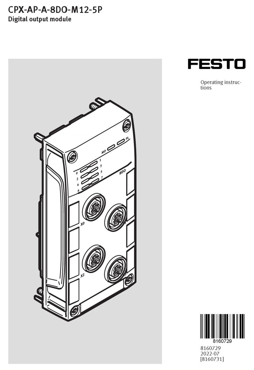
  9. Festo CPX-E-1CI User manual

Festo CPX-E-1CI User manual

Translation of the original instructions
1 About this document
This document describes the use of the above-mentioned product.
Certain aspects of use are described in other documents and must be observed
è 1.1 Further applicable documents.
1.1 Further applicable documents
Document Table of contents
Description of automation system CPX-E
(CPX-E-SYS)
Detailed description of automation system CPX-E
Instruction manual for use of automation system
CPX-E (CPX-E-SYS)
Instruction manual and important information on
assembly, electrical installation and mainten-
ance tasks for an automation system CPX-E
Description of counter module CPX-E-1CI
(CPX-E-1CI)
Detailed description of product function and
parameterisation options
Documentation of the components in an automa-
tion system CPX-E and the connected peripherals
Information on using the components
Documentation for the higher-order controller
and the additional participants in the network
Information on commissioning and paramet-
erisation of the components
Tab. 1 Further applicable documents
All available documents for the product èwww.festo.com/pk.
1.2 Product version
This document refers to the following product versions:
Product Version
CPX-E-1CI Counter module CPX-E-1CI, revision1 or later
Tab. 2 Product version
The product version can be identified from the product labelling or with the help
of appropriate software from Festo.
Appropriate software for determining the product version can be found in the
Festo Support Portal èwww.festo.com/sp.
Information on using the software can be found in the integrated Help function.
There may be an updated version of this document for these or later product ver-
sions.
• Check whether a corresponding version of this document is available on the
Festo Support Portal èwww.festo.com/sp.
1.3 Product labelling
The product labelling is located on the left-hand side of the module. Scanning the
printed Data Matrix Code with an appropriate device opens the Festo Support
Portal, with the information appropriate for the product. Alternatively, the Product
Key (11-digit alphanumeric code on the product labelling) can be entered in the
search field of the Support Portal.
You can find detailed information on the product labelling in the description of the
module è 1.1 Further applicable documents.
1.4 Specified standards
Version status
EN60529:2013-10 IEC60204-1:2014-10
EN61000-6-2:2005-08 IEC61131-2:2015-05
EN61000-6-4:2007-01 –
Tab. 3 Standards specified in the document
2 Safety
2.1 Safety instructions
– Take into consideration the legal regulations for the respective destination.
– Use the product only within the defined values è 13 Technical data.
– Observe labelling on the product.
– Observe further applicable documents.
– Store the product in a cool, dry, UV-protected and corrosion-protected envir-
onment. Ensure that storage times are kept to a minimum.
– Before working on the product: switch off the power supply and secure it
against being switched on again.
– Comply with the handling specifications for electrostatically sensitive devices.
2.2 Intended use
The product described in this document is intended only for use in automation
systems CPX-E.
Use the product only as follows:
– Use only in an industrial environment. Outside of industrial environments,
e.g. in commercial and mixed-residential areas, it may be necessary to take
measures to suppress interference.
– Use only in combination with modules and components that are permissible
for the respective product variant èwww.festo.com/catalogue.
– Only use the product if it is in perfect technical condition.
– Only use the product in original status without unauthorised modifications.
Only the conversions or modifications described in this and the further applic-
able documents are permitted.
2.3 Training of skilled personnel
Installation, commissioning, maintenance and disassembly should only be con-
ducted by qualified personnel.
The qualified personnel must be familiar with installation of electrical control sys-
tems.
3 Additional information
– Accessories èwww.festo.com/catalogue.
– Spare parts èwww.festo.com/spareparts.
4 Service
Contact your regional Festo contact person if you have technical questions
èwww.festo.com.
5 Product overview
5.1 Function
In an automation system CPX-E, the module offers the option of connecting an
encoder for detecting pulses. The encoder supply has an electronic fuse for pro-
tection against short circuit or overload. After the elimination of a short circuit or
overload, the encoder supply is switched on again automatically.
The module provides the following functions:
– Setting the counter
– Blocking the counter
– Latching
– Speed measurement
The module also provides 4digital inputs (I0...I3), each of which can be used to
trigger a particular function:
– Input I0: trigger latching
– Input I1: block latching
– Input I2: set counter
– Input I3: block counter
The debounce time of inputs I0...I3 and the module response can be set using
module parameters.
The following encoder types can be used with the module:
– Encoder 24VDC (singleended)
– Encoder 5VDC (differential or singleended)
You can find detailed information on the types of encoder that can be used in the
description of the module è 1.1 Further applicable documents.
8071179
Counter module
CPX-E-1CI
8071179
2018-02
[8071181]
Instructions|Use
Festo AG & Co. KG
Ruiter Straße 82
73734 Esslingen
Germany
+49 711 347-0
www.festo.com
5.2 Configuration
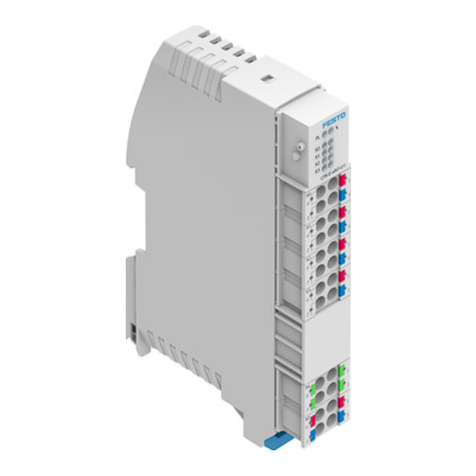
5.2.1 Product design
1LED indicators
2Terminal strip inputs I0 ... I1 [X0]
3Terminal strip inputs I2 ... I3 [X1]
4Terminal strip encoder input [X2]
5Terminal strip encoder supply
[X3]
6Terminal strip interlock
7Linking element
Fig. 1
5.2.2 Display components
1Module error [P] (red)
2Status of input I1 [X0] (green)
3Status of input I3 [X1] (green)
4Encoder error [X2] (red)
5Error in encoder supply [X3] (red)
6Normal operation of encoder sup-
ply [X3] (green)
7Normal operation of encoder [X2]
(green)
8Status of input I2 [X1] (green)
9Status of input I0 [X0] (green)
Fig. 2
The module-specific LED indicators are described below è 11.3 LED indicators.
The system-specific LED indicators are described in the documentation for the
automation system CPX-E è 1.1 Further applicable documents.
5.2.3 Connecting components
Connection [X0], [X1]1) Signal [X0] Signal [X1]
0 Input I0 Input I2
1 Input I1 Input I3
2 +24VDC input I0 +24VDC input I2
3 +24VDC input I1 +24VDC input I3
4 0VDC input I0 0VDC input I2
5 0VDC input I1 0VDC input I3
1) Inputs type1 and type3 according to IEC61131-2
Tab. 4 Connection X0, X1
NOTICE!
For encoders with "single ended" connection type, connections X2.1(A–),
X2.3(B–) and X2.5(0–) must not be connected.
Connection [X2] "Differential" signal "Single ended" sig-
nal
0 A+ A+
1 A– Do not connect
2 B+ B+
3 B– Do not connect
4 0+ 0+
5 0– Do not connect
Tab. 5 Connection X2
NOTICE!
Material damage to the module if both the 5V and 24V encoder supplies are con-
nected.
• Only use encoder supplies separately from one another.
Connection [X3] Signal
0 +24VDC encoder supply
1 +5VDC encoder supply
2 0VDC encoder supply
Connection [X3] Signal
3 0VDC encoder supply
4
5
Functional earthFE
Tab. 6 Connection X3
6 Transport and storage
• Observe specifications for environmental and storage conditions
è 13 Technical data.
7 Assembly
• Assemble the module as outlined in the “Instruction manual for use of auto-
mation system CPX-E” è 1.1 Further applicable documents
8 Installation
NOTICE!
Malfunction due to electromagnetic interference.
• Use screened cables only to connect the encoder.
• Connect screening to the connection for functional earthFE.
1. Make sure that the power supply is switched off.
2. Connect the lines to the terminal strips according to the “Instruction manual
for use of automation system CPX-E” è 1.1 Further applicable documents.
9 Commissioning
You can find information on commissioning the automation system CPX-E in the
“Instruction manual for use of automation system CPX-E”. Information on the
parameters can be found in the “Description of automation system CPX-E” and in
the descriptions of the modules used è 1.1 Further applicable documents.
9.1 Behaviour of the display components after error-free commissioning
[P] (red)1) [X2], [X3] (green) [X2] (red) [X3] (red)
Off Lit Off Off
1) Lights up until the module initialisation is completed.
Tab. 7 Display components after error-free commissioning
Information on troubleshooting in the event of incorrect behaviour can be found
in the “Description of automation system CPX-E” and the descriptions of the mod-
ules used è 1.1 Further applicable documents.
10 Maintenance
NOTICE!
Accumulation of heat due to reduced air supply to electronics.
• Keep the ventilation slots free and regularly remove contamination.
11 Diagnostics and fault clearance
11.1 Diagnostics options
Various options are available for diagnosing errors:
– Internal system diagnostics
– LED indicators on the product
11.2 Internal system diagnostics
The internal system diagnostics is described in the “Description of automation
system CPX-E” è 1.1 Further applicable documents.
11.3 LED indicators
The module-specific LED indicators are described in this document.
The system-specific LED indicators are described in the documentation for the
automation system CPX-E è 1.1 Further applicable documents.
Module error [P]1)
LED
(red)
Significance Remedy
Module error
Short circuit/overload in encoder supply
(error number2)
Check cables and connections.
Lit Undervoltage in operating
voltage/encoder supply (error number5)
Check power supplies and installation.
Module error [P]1)
LED
(red)
Significance Remedy
Parameterisation error (error number29) Check parameterisation and adjust.
Lit
Encoder error2) (error number108) è Tab. 11 Encoder error [X2]
Off
Normal operating status –
1) Lights up until the module initialisation is completed.
2) If monitoring via parameters is activated.
Tab. 8 Module error
Status of input I0…I3 [X0], [X1]
LED
(green)
Significance Remedy
Lit
Input active (logic1)
1 signal at input
–
Off
Input inactive (logic0)
0 signal at input
–
Tab. 9 Status of input I0 ... I3 [X0], [X1]
Normal operation of encoder [X2]
LED
(green)
Significance Remedy
Lit
Encoder in normal operation –
Off
Encoder error
(è Tab. 11 Encoder error [X2]) or module
not initialised
–
Tab. 10 Normal operation of encoder [X2]
Encoder error [X2]
LED
(red)
Significance Remedy
Encoder error (error number108)
Cable break Check cables and connections.
Tracking error Reduce frequency of input pulses.
Lit Zero pulse error Check “pulse/zero pulse” parameter and
adjust èDescription of module.
Off
Encoder in normal operation
(è Tab. 10 Normal operation of encoder
[X2]) or module not initialised
–
Tab. 11 Encoder error [X2]
Normal operation of encoder supply [X3]
LED
(green)
Significance Remedy
Lit
Encoder supply in normal operation –
Off
Error in encoder supply
(è Tab. 13 Error in encoder supply [X3]) or
module not initialised
–
Tab. 12 Normal operation of encoder supply [X3]
Error in encoder supply [X3]
LED
(red)
Significance Remedy
Lit
Short circuit/overload of encoder supply
(error number2)
Check cables and connections.
Off
Encoder supply in normal operation
(è Tab. 12 Normal operation of encoder
supply [X3]) or module not initialised
–
Tab. 13 Error in encoder supply [X3]
12 Disposal
ENVIRONMENT!
Send the packaging and product for environmentally sound recycling in accord-
ance with the current regulations èwww.festo.com/sp.
13 Technical data
General technical data
General technical data for
automation system CPX-E
Description of automation system CPX-E
è 1.1 Further applicable documents
Dimensions (length x width x
height)
[mm] 124.3 x 18.9 x 76.6
Product weight1) [g] 88
Mounting position Vertical/horizontal
Ambient temperature [°C] –5…+60 (–5…+50)2)
Storage temperature [°C] –20…+70
Air humidity
(non-condensing)
[%] 0…95
Assigned address space
(inputs/outputs)
[bytes] 12/2
Degree of protection in
accordance with EN60529
IP20
Protection against electric
shock (protection against dir-
ect and indirect contact in
accordance with
IEC60204-1)
Through the use of PELV circuits
(protected extra-low voltage)
Electromagnetic compatibil-
ity
To EN61000-6-2/-4
Module code/submodule
code (CPX-E-specific)
174/10
Module identification E-1CI
1) Including linkage
2) for horizontal mounting position
Tab. 14 General technical data
Power supply
Operating voltage supply
UEL/SEN
[VDC] 24±25%
Intrinsic current consumption
at nominal operating voltage
24V from UEL/SEN
[mA] 15
Reverse polarity protection Yes
Encoder supply 5VDC/
24VDC
[VDC] 5±5%/ 24±25 %
Continuous nominal current
of encoder supply
[mA] 500
Short circuit protection of
encoder supply
Yes
Undervoltage identification
Response threshold UEL/SEN [VDC] <16
Hysteresis UEL/SEN [VDC] 0.3…0.5
Response threshold, encoder
supply 5VDC
[VDC] 4.5
Tab. 15 Power supply
Encoder inputs
Max. input frequency of encoder signals1)
Differential [MHz] 2
Single ended [kHz] 250
Max. debounce time of encoder inputs1)
Differential [ns] 125
Single ended [µs] 1
1) Dependent on the connection type of the encoder, "differential" or "single ended"
Tab. 16 Encoder inputs

Other manuals for CPX-E-1CI

1

Other Festo Control Unit manuals

Festo Smart cubic CPA-SC Series User manual

Festo

Festo Smart cubic CPA-SC Series User manual

Festo CPX-FVDA-P2 User manual

Festo

Festo CPX-FVDA-P2 User manual

Festo SMH-AE1 M12 Series User manual

Festo

Festo SMH-AE1 M12 Series User manual

Festo CPX-FB40 Operating and installation instructions

Festo

Festo CPX-FB40 Operating and installation instructions

Festo HMP-x-B Series User manual

Festo

Festo HMP-x-B Series User manual

Festo CP-FB13-E Owner's manual

Festo

Festo CP-FB13-E Owner's manual

Festo CPX-E-PN User manual

Festo

Festo CPX-E-PN User manual

Festo VPPM-6L-L-1-G18-0L6H-V1N-S1C1 User manual

Festo

Festo VPPM-6L-L-1-G18-0L6H-V1N-S1C1 User manual

Festo CPX-E-4IOL User manual

Festo

Festo CPX-E-4IOL User manual

Festo CAMC-G-S1 User manual

Festo

Festo CAMC-G-S1 User manual

Festo CPX-M-FB20 Parts list manual

Festo

Festo CPX-M-FB20 Parts list manual

Festo Smart cubic CPVSC1-VI User manual

Festo

Festo Smart cubic CPVSC1-VI User manual

Festo CPE Series User manual

Festo

Festo CPE Series User manual

Festo CPE-10-PRS series User manual

Festo

Festo CPE-10-PRS series User manual

Festo MS6-SV Series User manual

Festo

Festo MS6-SV Series User manual

Festo VOFA-L26-T32C-M-G14-1C1 Series User manual

Festo

Festo VOFA-L26-T32C-M-G14-1C1 Series User manual

Festo CPX-E-PB User manual

Festo

Festo CPX-E-PB User manual

Festo VZBA-x-63-32x-x-V4V4T Series User manual

Festo

Festo VZBA-x-63-32x-x-V4V4T Series User manual

Festo CP-FB13-E Parts list manual

Festo

Festo CP-FB13-E Parts list manual

Festo VZXA M Series Parts list manual

Festo

Festo VZXA M Series Parts list manual

Festo MS6N-SV Installation instructions

Festo

Festo MS6N-SV Installation instructions

Festo VPPL User manual

Festo

Festo VPPL User manual

Festo VZQA-C-M22C-6-GG-V2V4E-1 User manual

Festo

Festo VZQA-C-M22C-6-GG-V2V4E-1 User manual

Festo MSE6-E2M Guide

Festo

Festo MSE6-E2M Guide

Popular Control Unit manuals by other brands

Allmatic AS24 Manual for installation

Allmatic

Allmatic AS24 Manual for installation

Rebel Technology Logoi Assembly guide

Rebel Technology

Rebel Technology Logoi Assembly guide

Kutai electronics ATS-PLC Operation manual

Kutai electronics

Kutai electronics ATS-PLC Operation manual

Interlogix NXG-7002 Installation sheet

Interlogix

Interlogix NXG-7002 Installation sheet

Kongsberg RSER200-4 Hardware description

Kongsberg

Kongsberg RSER200-4 Hardware description

Audioplex VC300 installation manual

Audioplex

Audioplex VC300 installation manual

Atkinson Electronics GSCM-mini-P manual

Atkinson Electronics

Atkinson Electronics GSCM-mini-P manual

Comelit 1259C Technical manual

Comelit

Comelit 1259C Technical manual

GEM eSyLite 629 operating instructions

GEM

GEM eSyLite 629 operating instructions

WAGO 750-429/040-001 manual

WAGO

WAGO 750-429/040-001 manual

Littelfuse SE-330 manual

Littelfuse

Littelfuse SE-330 manual

Isenberg 230.2720 installation manual

Isenberg

Isenberg 230.2720 installation manual

Dtrovision Pure Link DVI-DOC-F owner's manual

Dtrovision

Dtrovision Pure Link DVI-DOC-F owner's manual

Agilent Technologies 54751A manual

Agilent Technologies

Agilent Technologies 54751A manual

Vogtlin TetraTec Instruments red-y smart Series operating instructions

Vogtlin

Vogtlin TetraTec Instruments red-y smart Series operating instructions

SystemBase Eddy Series user guide

SystemBase

SystemBase Eddy Series user guide

Roger Technology H70/104AC Instructions and warnings for installation

Roger Technology

Roger Technology H70/104AC Instructions and warnings for installation

Distech Controls SOLSTYCE Series installation guide

Distech Controls

Distech Controls SOLSTYCE Series installation guide

manuals.online logo
manuals.online logoBrands
  • About & Mission
  • Contact us
  • Privacy Policy
  • Terms and Conditions

Copyright 2025 Manuals.Online. All Rights Reserved.