manuals.online logo
Brands
  1. Home
  2. •
  3. Brands
  4. •
  5. Festo
  6. •
  7. Control Unit
  8. •
  9. Festo FRM S-B Series User manual

Festo FRM S-B Series User manual

320496
(171 322)
Operating Instructions
Bedienungsanleitung
for Connection Module
ftir
Abzweig-Modul
Type FRM-.
.
.-S-B
Typ FRM-.
.
.-S-B
and nipple connector set
und
Nippelsatze
Conditions regarding the use of Festo
Was ist beim
Einsatz
vonFestoElementen
ZLI
equipment. beachten?
This is important for reasons of safety
1. It is most
krnporiant
that only properly instructed and
quaIlfled
personnel use
this
equipment.
2.
This
equipment should only be used
withIn
the
llm!ts
detailed in the
techmcal
specification.
Strict observance of
the technical
specification
should be ensured at all
times.
3. Correctly prepared compressed a,r should be used at
all times. When installing
theequipment
and thereafter, the
Customer
shall
ensurethattheenvironmentalconditionsat
the place of use are taken
Into
consideratbon.
4. If the equipment is incorporated in
a
system or used
wthin
safety
devices
or circuits, the Customer shall
r?nsure
that national and local safety laws and
regulatmns
are
ob-
served.
Die
Einhaltung
der
~ewals
angegebenen
Grenzwerte
ftir
Drticke,
Temperaturen
und
die
Beachtung
van
timwe~sen
ist
Voraussetzung
fur de
ordnungsgemafle
Funktion
und
daher
vorn
Anwender
unbedmgt
zu
gew~hrleisten
Es ist auf den
Setrieb
rnlt
ordnungsgemtil?
aufberelteter
Druckluft
ohne
aggressive
Median
zu
achten.
Aul3erdem
smd die Jeweiligen
Umweltbedmgungen
am
Emsatzwl
zu
berticksichtlgen.
Be!
Anwendung
van
Festo
Elementen
im
Sicherheitsbe-
refch
and
stets
such
dieiew%~ligenVorschr~ften
da
Eerufs-
genossenschaft
und
des
Technischen
Uberwachungs-
Vewns
bzw.
die
entsprechenden
nationalen
Best~mrnun-
gen zu
beachten.
5.
Should you
require
further information please contact
your local
F&o
office.
These instructions
are
important. Please keep them in
a
safe
place.
1.0 Preparing theconnection module
for attachment of additional
devices.
1.0 Umbau des
Abzweig-Mod&
bei
Anbau weiterer
Gergte
1.l
Application.
1.1 Anwendung
The connection module enables the
retro-fit-
ting of a pressure regulator for a second,
lowerlevelpressure circuit,and/orapressure
switch for electrical feedback.
A hexagon connector set is required for mak-
ing the connections between the units.
Sic
konnen
einen
Druckluftregler
und/oder
einen Druckschalter
nachtraglich
anschlie-
l3en
fur eine
niedrigere
Druckstufe
bzw.
fur
ei-
ne elektrische Uberwachung.
Dazu mussen Sie
Nippelsatze
bestellen
1.2 Disassembly
-
Remove cover plate
@.
-
Remove mounting clip
@
with the aid of a
screwdriver.
1.2 Demontage des
Abzweig-Moduls
-
Abdeckschild’@
abnehmen.
-
Montiergabel @mit Hilfe von einem
Schraubendreher herausziehen
-
Remove unwanted connector, and replace
-
Das auszutauschende
Verbindungsstuck
with correct part. herausziehen,passendesmontieren.
2.0 Assembly kit for 2.0 Montagebausatz
Type FRM-.
.
.
-S-B
Typ FRM-.
.
.-S-B
Connector for attachment of
additional devices
/
Nippel
fur Anbau weiterer
Gerate
Double nipple for attachment of Type PEV
pressureswitchorTypeSDEpressure
sensor. Screw into threaded hole
/
Doppelnippel
fur
Anbau des Druckschal-
tersTypPEV oderDrucksensors
SDE.
Einschrauben in
Gewindebtichse.
Type
I
Typ
FRM-%-S-B
To plug unused
connections /
zumVerschlief3en
nicht
benotrgter
Anschltisse
Installation nipple for attachment of Type
PEVpressure
switch
orType
SDE pressure
sensor. Install with mounting clip
/
Einbaunippel
fur
Anbau des Druckschal-
tersTypPEV oderDrucksensors
SDE.
Montage mit Montiergabel.
Type
ITyp
FRM-i/d
to /bis
%-S-B
2.1 Operating parts and connections 2.1
Bedienteile
und
Anschltisse
a
PVC plug with sealing ring for
connections
G1/a
and G
%
IS0
@
Threaded bush with O-ring
@
Connection module (basic body)
@
Hexagon nipple set with O-rings
(for connections G
‘/a
to G
j/z)
@
Mounting clips (6 off)
(4 for horizontal and 2 for vertical
connections for attachment of additional
devices)
@
Cover plate
@
Blindstopfen (mit Dichtring)
aus
PVC
fi_ir
Anschlu8
G
%
und G
j/a
@
Gewindebtichse
(mit O-Ring)
@
Abzweig-Modul
(Grundkerper)
@
Nippelsatz mit
0-Ringen
(Anschlul3
G
%
bis G
l/z)
@
Montiergabel
(6~)
(4
St&k
fi_ir
waagrechte,
2
Sti_ick
ftir
senkrechte
Anschltisse
zum Anbau
weiterer
Gertite)
@
Abdeckschild
3. Technical
data
3. Technische
Daten
Vw
1
TY
P
Part No.
/Teile-Nr.
Connector size
front/back
/
Anschlu8gr68e
vorne/hinten
FRM-‘/a-S-B
FRM-Y-S-B
FRM-YE-S-B
FRM-‘/Z-S-B
33012 33013 33014 33015
G
‘/a
G
‘A
G
%
G
‘/z
Supply pressure
p,
max.
/
14bar
Eingangsdruck
p,
max.
Nominal bore
/
Nennweite
8,5
mm
11 mm
15
mm
19 mm
Medium temperature
/
14 to 140
‘F/-l0
to
+60
‘C
/
-10 bis +60
YZ
Mediumstemperatur
Assembly position
/
Einbaulage any
/
beliebig
Material
/
Werkstoffe
Housing: Glass fibre reinforced polyamide;
Seals: Hard PVC;
NBR;
Connections: MS
/
Gehtiuse:
Polyamid,
glasfaserversttirkt;
Dichtungen: PVC
-
hart,
NBR;
Anschkisse:
MS
Connectionstop/bottom I
Anschlul3gr68e
oben/unten
4. Nipple
se&
for assembly units
Type
4.
Montagebausatz
ftir
Nippelsatz
TYP
FRM-‘/a-BS-S-B
Part No. 33446
FRM-‘/a-BS-S-B
Teile-Nr. 33446
FRM-‘A-.
-l/z-BS-S-B
Part No. 33447
FRM-‘A-.
-%BS-S-B
Teile-Nr. 33447
4.1 Required accessories
Hexagon nipple set Type
FRM-%-ES-S-B
is
required to attach Type PEV pressure switch
and Type LR-.
-%S
regulator to Type
FRM-‘/e-S-B
connection module.
4.1 Notwendiges
Zubeh6r
Nippelsatz Typ
FRM-%BS-S-B
bei
Mon-
tage von Druckschalter Typ PEV und
Reg-
ler Typ
LR-.,.-Y-S
an Abzweig-Modul
FRM-Y-S-B.
Hexagon nipple set Type
FRM-j/d-.
-j/z-BS- Nippelsatz Typ
FRM-l/d-.
-j/z-BS-S-B
bei
S-B is required to attach Type PEV pressure Montage von Druckschalter Typ PEV und
switch and Type LR-r/&S-B regulator to Type
Regler
Typ
LR-Y-S-B
anAbzweig-ModulTyp
FRM-52
to
%-S-B
connection module.
FRM-j/d
bis
%-S-B.
5. Securing the nipple adaptors
5. Montage der eingesetzten
Nippel
Push mounting clips in far enough to rest Montiergabel so weit
hineindrticken
(evtl.
mit
against housing reinforcement. leichtem Klopfen der
Handflache),
daf3
sie
Mounting clips are reusable. auf der
Gehause-Verstarkerrippe
aufliegt
(An-
schlag)
Die
Montiergabeln
sind wiederverwendbar.
Note:
Hinweis:
The mounting clip may fly out during disas-
Bei
der Demoniage kann die Montiergabel
sembly. evtl.
herausspringen.

This manual suits for next models

4

Other Festo Control Unit manuals

Festo EFSD User manual

Festo

Festo EFSD User manual

Festo MS6-SV Series User manual

Festo

Festo MS6-SV Series User manual

Festo CPX-E-1CI User manual

Festo

Festo CPX-E-1CI User manual

Festo VZXA-C/W-M-V4 Series User manual

Festo

Festo VZXA-C/W-M-V4 Series User manual

Festo DSMI Series User manual

Festo

Festo DSMI Series User manual

Festo CP-FB8 Parts list manual

Festo

Festo CP-FB8 Parts list manual

Festo LF-D Series User manual

Festo

Festo LF-D Series User manual

Festo CP-FB11-E Parts list manual

Festo

Festo CP-FB11-E Parts list manual

Festo CPA-SC Series User manual

Festo

Festo CPA-SC Series User manual

Festo CPX-FB39 Operating and installation instructions

Festo

Festo CPX-FB39 Operating and installation instructions

Festo MS6(N)-SV-...-C User manual

Festo

Festo MS6(N)-SV-...-C User manual

Festo CPX-2AE Series Parts list manual

Festo

Festo CPX-2AE Series Parts list manual

Festo VAPB Series User manual

Festo

Festo VAPB Series User manual

Festo CPVSC1-M1H-D-H-M5C User manual

Festo

Festo CPVSC1-M1H-D-H-M5C User manual

Festo CPX-FB23 Operating and installation instructions

Festo

Festo CPX-FB23 Operating and installation instructions

Festo CPX-E-EP User manual

Festo

Festo CPX-E-EP User manual

Festo ERMB User manual

Festo

Festo ERMB User manual

Festo CPV..-DI01 series User manual

Festo

Festo CPV..-DI01 series User manual

Festo CPX-CTEL-4-M12-5POL User manual

Festo

Festo CPX-CTEL-4-M12-5POL User manual

Festo VACC-S13-11-K4-1-EX4A User manual
Festo

Festo VACC-S13-11-K4-1-EX4A User manual

Festo VSNZ-FT-T32C-M F-P1-T6 Series User manual

Festo

Festo VSNZ-FT-T32C-M F-P1-T6 Series User manual

Festo VZQA-C-M22C Series Setup guide

Festo

Festo VZQA-C-M22C Series Setup guide
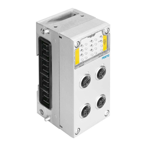
Festo CDVI Series Parts list manual

Festo

Festo CDVI Series Parts list manual

Festo CPX-E-EP User manual

Festo

Festo CPX-E-EP User manual

Popular Control Unit manuals by other brands

GOK 0271 Assembly and operating manual

GOK

GOK 0271 Assembly and operating manual

Siemens SINUMERIK 808D operating instructions

Siemens

Siemens SINUMERIK 808D operating instructions

Parker DP-V1 Technical manual

Parker

Parker DP-V1 Technical manual

Verizon FiOS-ZBMod1 user guide

Verizon

Verizon FiOS-ZBMod1 user guide

ABB 650 series Applications manual

ABB

ABB 650 series Applications manual

Kessel Staufix Series Installation and operating instructions

Kessel

Kessel Staufix Series Installation and operating instructions

TRIGA TR-CONTROL-6 Installation and maintenance instructions

TRIGA

TRIGA TR-CONTROL-6 Installation and maintenance instructions

Flex BMR 481 P1E+ user guide

Flex

Flex BMR 481 P1E+ user guide

Beninca CP.B24 manual

Beninca

Beninca CP.B24 manual

ARMANO DAS operating instructions

ARMANO

ARMANO DAS operating instructions

LS ELECTRIC XGT Series user manual

LS ELECTRIC

LS ELECTRIC XGT Series user manual

Vimar Elvox ECP2 Connection and operating manual

Vimar

Vimar Elvox ECP2 Connection and operating manual

Eaton XNE-1SWIRE user manual

Eaton

Eaton XNE-1SWIRE user manual

GEM B22 operating instructions

GEM

GEM B22 operating instructions

Beckhoff EP7211-0034 Documentation

Beckhoff

Beckhoff EP7211-0034 Documentation

Texas Instruments TPS54521EVM-607 user guide

Texas Instruments

Texas Instruments TPS54521EVM-607 user guide

AVE AF927PLUS Installation and user manual

AVE

AVE AF927PLUS Installation and user manual

Taco Comfort Solutions ZVC406 instruction sheet

Taco Comfort Solutions

Taco Comfort Solutions ZVC406 instruction sheet

manuals.online logo
manuals.online logoBrands
  • About & Mission
  • Contact us
  • Privacy Policy
  • Terms and Conditions

Copyright 2025 Manuals.Online. All Rights Reserved.