manuals.online logo
Brands
  1. Home
  2. •
  3. Brands
  4. •
  5. Festo
  6. •
  7. DC Drive
  8. •
  9. Festo DLGF User manual

Festo DLGF User manual

Original instructions
1 Further applicable documents
All available documents for the product èwww.festo.com/pk.
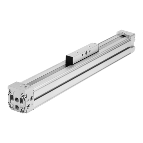
The DLGF linear drive is designated as product or drive in these operating instruc
tions.
2 Safety
2.1 General safety information
– Take into consideration the ambient conditions at the location of use.
– Only use the product in original status without unauthorised modifications.
– Observe labelling on the product.
– Observe further applicable documents.
– Store the product in a cool, dry, UVprotected and corrosionprotected environ
ment. Ensure that storage times are kept to a minimum.
– Prior to mounting, installation and maintenance work: Switch off compressed
air supply and secure it from being switched back on.
– Observe tightening torques. Unless otherwise specified, the tolerance is
±20%.
2.2 Intended use
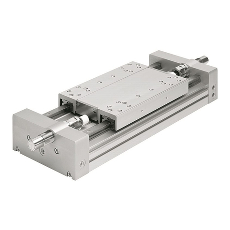
The product is intended for the spacesaving transport of masses.
The product is approved for rotor/slide operating mode.
Fig. 1
2.3 Foreseeable misuse
Mechanical movement of rotor/slide at high speed creates a vacuum in the piston
chamber. This vacuum can pull the sealing band into the piston chamber. This res
ults in severe leakage and unacceptable levels of acceleration (e.g. in vertical
mounting position).
Only move rotor/slide mechanically at low speeds.
2.4 Qualification of specialized personnel
Installation, commissioning, maintenance and disassembly should only be con
ducted by qualified personnel.
The specialized personnel must be familiar with the installation and operation of
electrical and pneumatic control systems.
3 Further information
– Accessories èwww.festo.com/catalogue.
– Spare parts èwww.festo.com/spareparts.
4 Service
Contact your regional Festo contact person if you have technical questions
èwww.festo.com.
5 Product overview
5.1 Function
When the pneumatic ports are pressurized alternately, the piston moves back
wards and forwards in the profile barrel. The rigid connection to the piston causes
the rotor/slide to move too. A sealing band spans the slot required in the profile
barrel.
5.2 Layout
DLGF-G
1Bores for direct mounting in the
cover
2Pneumatic connection
3Slide
4Mounting interface for connection
of working load
5Bores for direct/profile mounting
in the profile barrel
6Sealing band
7Groove for
Proximity sensor
Fig. 2
DLGF-KF
1Bores for direct mounting in the
cover
2Pneumatic connection
3Slide (mounted on rotor)
4Mounting thread for payload
5Bores for direct/profile mounting
in the profile barrel
6Guide rail
7Slot for proximity sensor
Fig. 3
6 Transport
NOTICE!
Unexpected movement of components. The rotor/slide is unbraked and can move
freely.
• Secure rotor/slide during transport.
– Take product weight into account è13 Technical data.
–Maintain support clearance£300mm when attaching transportation aids.
7 Assembly
7.1 Preparation
– Avoid damage and contamination to the sealing band.
– Do not modify the screws and threaded pins.
Exception: Immediate requirement for change in this instruction manual.
– Place the product in such a way that the control sections can be reached
(e.g.adjusting screws).
– Install product without torsional stresses.
– Fasten product to a mounting surface with flatness of 0.05% of the stroke
length, but max. 0.5mm.
– For gantry applications, attention must also be paid to parallel alignment or
product heights in alignment of the products. For further information please
contact your local Festo Service centre.
– If needed: Select mounting components or accessories
èwww.festo.com/catalogue.
To avoid collisions, attach the mounting components outside the positioning
range.
Linear drive
DLGF
8069099
201703
[8069101]
Instruction manual  Operation
Festo AG & Co. KG
Ruiter Straße 82
73734 Esslingen
Deutschland
+49 711 3470
www.festo.com
7.2 Direct mounting
Fig. 4
1. Attach drive paying attention to the minimum number of screws used in pairs
(in this example: 2 pairs of screws):
– On the bores in the profile or cover (with DLGF)
– On the bores in the cover (with DLGF...W)
Maintain a maximum support clearance of 300mm at all times. With
DLGF...W where necessary provide external support (e.g. from the machine
frame).
2. Tighten screws uniformly to the following tightening torque.
DLGF-... 20 25 32 40
Minimum number of pairs of screws depending on stroke
50…150 [mm] 2 2 2 2
200 [mm] 2 2 2 3
250 [mm] 2 2 3 3
300 [mm] 3 3 3 3
350…450 [mm] 3 3 3 4
500…600 [mm] 4 4 4 4
650…750 [mm] 4 4 4 5
800…1000 [mm] 5 5 5 5
Screw size and tightening torque
Bolt M4 M5 M6 M6
Tightening torque [Nm] 2.5 ± 10% 5.8 ± 20% 7.7 ± 20% 8.2 ± 10%
Tab. 1
7.3 Attachment
Fig. 5
NOTICE!
A warped attachment component bends the slide and shortens the service life of
the guide.
• Use an attachment component with an even surface.
Flatness with recirculating ball bearing: t = 0.01mm
– Position the payload in such a way, that the breakdown torque (parallel to the
axis of motion) and lever arm remains as low as possible.
– Avoid collisions of tool and payload with attachments.
– For attachment components with their own guide:
Adjust the guides of the tool and drive so that they are exactly parallel, or use a
connection that permits tolerance compensation. In this way, the guide is not
overloaded.
On DLGF-G in basic version:
• Attach mounting element (e.g. moment compensator DARDL8) to slide with
screws.
Fig. 6
DLGF-G-... 20 25 32 40
Screw S M4 M4 M4 M4
Tightening torque M [Nm] 3 ± 10% 3 ± 10% 3 ,4± 10% 3 ,4± 10%
Tab. 2
On DLGF-KF with recirculating ball bearing:
• Fasten the attachment to the slide with screws and centring elements. Pay
attention to the maximum screwin depth D and the tightening torque.
Attachment of mounting component from above/front:
Fig. 7
DLGF-KF-... 20 25 32 40
Mounting from above
Screw S1M4 M5 M5 M6
Max. screwin depth D1[mm] 8.8 9.8 10.3 10.3
Tightening torque M1[Nm] 2.2 4.5 4.5 7.5
Centring H7 [mm] Æ 7 Æ 9 Æ 9 Æ 12
Mounting from front
Screw S2M3 M4 M3 M4 M4 M5 M4 M6
Max. screwin depth D2[mm] 7 7 7 9 7.5 10 8 10
Tightening torque M2[Nm] 1 2.2 1 2.2 2.2 4.5 2.2 7.5
Tab. 3
7.4 Mounting accessories
Position scanning with proximity sensors:
– Press proximity switch into the grooves 7 è5.2 Layout.
– Avoid external influences from magnetic or ferritic parts in the vicinity of the
proximity sensors (maintain a minimum distance of 10mm).
– To avoid contamination, use groove covers on all unused grooves
èwww.festo.com/catalogue.
To set the speed:
– Use oneway flow control valves in the supply ports.
To secure the payload from dropping when a pressure failure occurs:
– Use check valves.
8 Pneumatic installation
1Supply port for movement to the
right
2Supply port for movement to the
left
3Subbase
4Sealing ring
Fig. 8
1. Select suitable supply ports.
The compressed air supply can be onesided or at both ends.
In addition to the supply ports provided exfactory, a base plate can provide
a port 3 (èenlarged image). When a base plate is used, attachment must
be made using the cover bores. This is the only way to seal the Orings with
enough contact force.
2. Connect hoses to supply ports.
9 Start-up
Preparation
NOTICE!
Unexpected movement of components.
• Keep foreign objects out of the positioning range.
• Initiate startup at low speed.
– Slowly supply complete system with air. For slow startup pressurisation, use
onoff valve HEL.
With medium or large payloads and/or at high speeds:
– Use sufficiently large arrester fixtures.
Without the use of external arrester fixtures, the product can contend with the
maximum speeds and payloads defined in catalogue details or in technical
data.
Processing
NOTICE!
Risk of collision by payloads that protrude through the rotor/slide.
• Only turn adjusting screws while the rotor/slide is stationary.
Fig. 9
1. First of all, almost close the oneway control valves on both sides com
pletely, then unscrew them one complete turn.
2. Initially exhaust drive simultaneously at both sides.
ÄThis causes the rotor/slide to move slightly to a point of balance
3. Then exhaust the drive on just one side.
ÄThis causes the rotor/slide to move into an end position.
4. Start the test run.
5. If needed: Correct speed at the restrictor check valves. The rotor/slide
should reach the end positions without striking them harshly or recoiling.
10 Maintenance
10.1 Cleaning
Do not clean the guide elements (e.g. guide rails).
• Clean the outside of the product with a soft cloth. Do not use aggressive
cleaning agents.
10.2 Lubrication
NOTICE!
Lubrication of the basic version of the shaft is not necessary.
Lubrication of recirculating ball bearing (DLGF-KF)
Fig. 10
1. Calculate load comparison factorfv with the help of the formula for com
bined loads è13 Technical data.
2. Read off lube interval Sint èFig.11.
3. Oil or grease the guide at all relubrication openings èFig.10.
When pressing in grease: Move slide slowly to and fro by hand.
– Accessories and permitted lubricant èMaintenance accessories.
– Amount of lubricantèTab. 4.
Fig. 11
NOTICE!
The lubrication interval Sint is dependent on the load acting on the product.
Load factors include e.g.:
• Dusty and dirty environment
•Nominal stroke > 2000mm or < 300mm
•Speed > 2m/s
•Ambient temperature > +40°C
•Service age of product > 3years
• Travel profile matches triangular operation (frequent acceleration and braking)
If one of these factors applies:
• Halve lubrication interval Sint.
If several factors apply at the same time:
• Divide service interval Sint by four.
Size 20 25 32 40
Lubricant quantity at each
lubricating point
[g] 0.3 0.5 1.7 1.9
Tab. 4
Maintenance accessories
Designation Part number1) Type1)
DLGFKF20/25
Oil gun 8041022 AZTPSL
Metering needle kit 8075522 AZTNDSG
Metering needle for DLGF20: Green,
angled 45°
Metering needle for DLGF25: Olive,
angled 45°
Cartridge 8073523 AZLGH1C10,
(Elkalub VP 922, ChemieTechnik Co.,
Vöhringen)
DLGFKF32/40
Grease gun with needlepointed
nozzle
647958 LUB1
Lubrication adapter, angled output 8073388 LUB1TRW
Lubricating grease 8073786 ELKALUB VP 922,
(ChemieTechnik, Vöhringen)
1) Spare parts catalogue ➔www.festo.com/spareparts
Tab. 5
11 Malfunctions
11.1 Fault clearance
Fault description Cause Remedy
Irregular movement of slide Oneway flow control valve not
installed correctly
Choke with exhaust air as far as
possible (not with supply air).
Malfunctions in position sens
ing
Ferritic parts in the vicinity of
the proximity switch
Use parts of nonmagnetic
materials or maintain minimum
distances
è7.4 Mounting accessories.
Linear actuator integrated in a
distorted manner
Fasten the linear actuator to a
flat base.
Seal worn Replace wearing parts:
– Self repair with a set of
wearing parts
– Repair at Festo
Heavy leakage
Sealing band pressed/sucked
in
For unpressurized linear drive:
– Loosen the tubing connec
tion and move the slide
twice by hand through the
entire stroke (if necessary,
move fixed stops into the
end position).
– Avoid low pressure in the
piston chamber (e.g. only
move the depressurised
slide slowly).
Lack of air volume – Increase connection cross
section.
– Place volume upstream.
Linear actuator does not
achieve the desired speed.
High friction or counteracting
force
Observe limit values.
Tab. 6
11.2 Repair
Send product to the Festo repair service for repair.
12 Recycling
ENVIRONMENT!
Dispose of the packaging and product according to the valid provisions of envir
onmentally sound recycling èwww.festo.com/sp.
13 Technical data
Size 20 25 32 40
Design Rodless drive
Mode of operation Doubleacting
Cushioning Pneumatic cushioning,
Selfadjusting on both sides
Pneumatic connection M5 G1/8 G1/8 G1/4
Speed [m/s] 0.07…1.5
Repetition accuracy [mm] ±0.05
Mounting position Optional
Operating pressure [bar] 2…8 1.5…8
Operating medium Compressed air acc. to ISO 85731:2010 [7::]
Size 20 25 32 40
Notes on the operating/pilot
medium
Lubricated operation possible (in which case lubricated
operation will always be required)
Ambient temperature [°C] 0…60
Theoretical force at 6 bar [N] 188 295 483 754
Weight DLGF‑G
Basic weight with 0mm
stroke
[g] 590 957 1703 3234
Additional weight per 10mm
stroke
[g] 28.2 35.3 54.7 80.6
Weight DLGF‑KF
Basic weight with 0mm
stroke
[g] 1015 1640 2829 5585
Additional weight per 10mm
stroke
[g] 35.5 45.5 69.4 105.5
Materials
Cover, housing, rotor/slide Aluminium
Seals NBR, TPEU (PU)
Guide band, guide (DLGF‑KF),
scraper
POM
Sleeve, stop Steel
Tab. 7
Size 20 25 32 40
Loading characteristics, DLGF‑G
Formula for combined loads:
Permitted forces and torques, DLGF‑G
+Fzmax [N] 54 95 138 456
Fzmax [N] 98 164 276 662
Mxmax [Nm] 0.6 1.1 1.8 7.7
Mymax [Nm] 2.2 4.5 7.6 37.6
Mzmax [Nm] 0.7 1.4 2.9 11.2
Characteristic load values, DLGF‑KF
Formula for combined loads (load comparison factor):
Permitted forces and torques, DLGFKF
Fymax [N] 600 1000 1300 1700
+Fzmax [N] 400 700 950 1150
Fzmax [N] 700 1200 1600 2000
Mxmax [Nm] 5.4 12.3 30 54
Mymax [Nm] 15 30 50 90
Mzmax [Nm] 15 30 50 90
Tab. 8

Other Festo DC Drive manuals

Festo DGC-8 Series User manual

Festo

Festo DGC-8 Series User manual

Festo DAPS-...-R-...-F...-...-MW Series User manual

Festo

Festo DAPS-...-R-...-F...-...-MW Series User manual

Festo DGCI Series User manual

Festo

Festo DGCI Series User manual

Festo DGP-8 User manual

Festo

Festo DGP-8 User manual

Festo DSR-10-180-P User manual

Festo

Festo DSR-10-180-P User manual

Festo SLG-8 Series User manual

Festo

Festo SLG-8 Series User manual

Festo DGO A-B Series User manual

Festo

Festo DGO A-B Series User manual

Festo EGC-50-TB Parts list manual

Festo

Festo EGC-50-TB Parts list manual

Festo DNCM POT Series User manual

Festo

Festo DNCM POT Series User manual

Festo DRRD-12 User manual

Festo

Festo DRRD-12 User manual

Festo DFPI ND2P-E-NB3P Series User manual

Festo

Festo DFPI ND2P-E-NB3P Series User manual

Festo FKP Series User manual

Festo

Festo FKP Series User manual

Festo DFPD-HD S Series User manual

Festo

Festo DFPD-HD S Series User manual

Festo DNG Series Setup guide

Festo

Festo DNG Series Setup guide

Festo DAPS Series User manual

Festo

Festo DAPS Series User manual

Festo CMMT-ST-C8-1C-...-S0 Series User manual

Festo

Festo CMMT-ST-C8-1C-...-S0 Series User manual

Festo EMCA-EC-67 CO Series User manual

Festo

Festo EMCA-EC-67 CO Series User manual

Festo EMCS-ST User manual

Festo

Festo EMCS-ST User manual

Festo EMCS-ST User manual

Festo

Festo EMCS-ST User manual

Festo EMCA-EC-67 CO Series Operating and installation instructions

Festo

Festo EMCA-EC-67 CO Series Operating and installation instructions

Festo DFPI-...D2P-C1V-NB3P series User manual

Festo

Festo DFPI-...D2P-C1V-NB3P series User manual

Festo DFPI Series User manual

Festo

Festo DFPI Series User manual

Festo EMCS-YY-ST Reference guide

Festo

Festo EMCS-YY-ST Reference guide

Festo DRRD-...-P..E Series User manual

Festo

Festo DRRD-...-P..E Series User manual

Popular DC Drive manuals by other brands

DINAMIC OIL TA Series user manual

DINAMIC OIL

DINAMIC OIL TA Series user manual

Danfoss VLT HVAC Drive FC 102 installation instructions

Danfoss

Danfoss VLT HVAC Drive FC 102 installation instructions

Eaton Cutler Hammer PowerXL DC1 E1 Series Parameter manual

Eaton

Eaton Cutler Hammer PowerXL DC1 E1 Series Parameter manual

Rockwell Automation Reliance Electric MD65 user manual

Rockwell Automation

Rockwell Automation Reliance Electric MD65 user manual

Siemens SINAMICS SM150 Operating and installation instructions

Siemens

Siemens SINAMICS SM150 Operating and installation instructions

Rexnord Falk Quadrive A Mounting & installation

Rexnord

Rexnord Falk Quadrive A Mounting & installation

ZIEHL-ABEGG ZA dyn 4B 110 Original operating instructions

ZIEHL-ABEGG

ZIEHL-ABEGG ZA dyn 4B 110 Original operating instructions

GFA ELEKTROMAT SI 40.15-40,00 Ex installation instructions

GFA

GFA ELEKTROMAT SI 40.15-40,00 Ex installation instructions

Bosch BDU3740 owner's manual

Bosch

Bosch BDU3740 owner's manual

Texas Instruments BOOATXL-DRV8301 user guide

Texas Instruments

Texas Instruments BOOATXL-DRV8301 user guide

YASKAWA CANopen SI-S3 Technical manual

YASKAWA

YASKAWA CANopen SI-S3 Technical manual

SOMFY JR RU 30 instructions

SOMFY

SOMFY JR RU 30 instructions

Honeywell CORE Drive quick start guide

Honeywell

Honeywell CORE Drive quick start guide

Rhymebus RM6E1 Series Operation manual

Rhymebus

Rhymebus RM6E1 Series Operation manual

Unimotion MCE Assembly and maintenance instructions

Unimotion

Unimotion MCE Assembly and maintenance instructions

Toshiba ATAPI installation manual

Toshiba

Toshiba ATAPI installation manual

HATO 300 SILENT 1000N operating manual

HATO

HATO 300 SILENT 1000N operating manual

ABB ACS880-01 Series Quick installation guide

ABB

ABB ACS880-01 Series Quick installation guide

manuals.online logo
manuals.online logoBrands
  • About & Mission
  • Contact us
  • Privacy Policy
  • Terms and Conditions

Copyright 2025 Manuals.Online. All Rights Reserved.