manuals.online logo
Brands
  1. Home
  2. •
  3. Brands
  4. •
  5. Festo
  6. •
  7. DC Drive
  8. •
  9. Festo DFPI ND2P-E-NB3 Series User manual

Festo DFPI ND2P-E-NB3 Series User manual

Translation of the original instructions
© 2020 all rights reserved to Festo SE & Co. KG
1 About this document
This document describes the use of the above-mentioned product.
1.1 Applicable documents
– Operating instructions for proximity switch
– Assembly instructions for connecting cable
– Assembly instructions for adapter kit
All available documents for the product èwww.festo.com/sp.
2 Safety
2.1 General Safety Instructions
– Only use the product in original status without unauthorised modifications.
– Only use the product if it is in perfect technical condition.
– Use only proximity sensors approved for the product.
– Take into consideration the ambient conditions at the location of use.
– Observe labelling on the product.
Operating medium
– Only use compressed air in accordance with the specifications
è 15 Technical data.
– Use only unlubricated compressed air under normal conditions. Once the
product has been used with lubricated compressed air, it must continue to be
operated with lubricated compressed air only.
Return to Festo
Hazardous substances can endanger the health and safety of personnel and
cause damage to the environment. To prevent hazards, the product should only
be returned upon explicit request by Festo.
– Consult your regional Festo contact.
– Complete the declaration of contamination and attach it to the outside of the
packaging.
– Comply with all legal requirements for the handling of hazardous substances
and the transport of dangerous goods.
2.2 Intended Use
The linear drive DFPI-...-E-NB3... is intended for regulation in process systems. It is
particularly appropriate for pneumatic positioning under harsh ambient condi-
tions.
2.3 Training of Qualified Personnel
Installation, commissioning, maintenance and disassembly may only be per-
formed by qualified personnel. Personnel must be familiar with the installation of
pneumatic control systems.
3 Further information
– Accessories èwww.festo.com/catalogue.
– Spare parts èwww.festo.com/spareparts.
4 Service
Contact your regional Festo contact person if you have technical questions
èwww.festo.com.
5 Product overview
5.1 Function
Pressurising and exhausting the cylinder chambers causes the piston rod connec-
ted to the piston to move back and forth.
The integrated displacement encoder transmits the current piston position to the
higher-order system as an analogue voltage or current signal.
G
Fig. 1
Proximity sensors can be installed with an adapter kit for additional binary sens-
ing of the position èwww.festo.com/catalogue.
5.2 Configuration
5.2.1 Product design
The linear drive consists of a double-acting pneumatic cylinder with integrated
displacement encoder. For mounting, the linear drive has a mounting interface in
accordance with ISO15552 at the bearing cap and the connection cap.
Design of DFPI-...-ND2P-E-NB3P
1Housing
2Air duct
3Earth terminal
4Mounting interface in accordance
with ISO 15552
5Mounting kit interface for external
positioner
6Retaining screw for cover
7Retaining screw for housing
8Electrical and pneumatic connec-
tion (under the protective cap)
9Piston rod with mounting thread
for accessories
10 Spanner flat
11 Bearing cap
12 Tie rod
13 End cap
Fig. 2 DFPI-...-...-ND2P-E-NB3P
8145396
DFPI-...-ND2P-E-NB3
Linear drive
8145396
2020-09e
[8145398]
Operating instructions
Festo SE & Co. KG
Ruiter Straße 82
73734 Esslingen
Germany
+49 711 347-0
www.festo.com
Design of DFPI-...-ND2P-E-NB3P9/M12
1Plug M12x1, A-coded
2Pneumatic connection G y
(extend piston rod)
3Pneumatic connection G y (retract
piston rod)
4Air duct
5Cable connector M16 x 1.5
Fig. 3 DFPI-...-…-ND2P-E-NB3P9/M12
6 Transport and storage
WARNING!
Danger of crushing. Danger of shearing.
Body parts can be crushed or severed if the product falls.
• Use appropriate load handling equipment.
• Do not use the air duct as a handhold for carrying.
– When dispatching used products: comply with all legal requirements for the
handling of hazardous substances and the transport of dangerous goods. For
return to Festo è 2.1 General Safety Instructions.
– Remove all attachments.
– Store the product in a cool, dry, UV-protected and corrosion-protected envir-
onment. Ensure that storage times are kept to a minimum.
7 Assembly
Any mounting position can be used.
1. Remove all transport packaging. The material used in the packaging has been
specifically chosen for its recyclability (exception: oil-impregnated paper =
residual waste).
2. Mount the drive with the retaining screws on the bearing cap and on the end
cap. Tighten the retaining screws evenly.
– Tightening torques è Tab. 1.
Piston diameter Tightening torque [Nm]
100 10
125 24
160 70
200 70
250 150
320 250
Tab. 1
When using additional proximity sensors
NOTICE!
When linear drives are installed too close to each other, the cylinder magnet can
disturb the proximity sensor on the adjacent linear drive.
1. Mount sensor bracket on the tie rod.
– Tightening torque: 0.6…1 Nm
2. Mount the proximity sensors è 1.1 Applicable documents.
3. Check minimum distances to ferritic and magnetic materials. Position the
drive to ensure trouble-free operation.
4. Mount the drive.
When mounting accessory parts on the piston rod
1. Attach accessory parts to the male thread of the piston rod (è Fig.2,9).
2. Tighten nut and accessories.
8 Installation
8.1 Pneumatic Installation
8.1.1 DFPI-...-ND2P-E-NB3P
1Pneumatic connection: retract
piston rod
2Pneumatic connection: extend
piston rod
Fig. 4
1. Prepare pneumatic connection.
– Check whether check valves are required. These will prevent the move-
able mass from sliding down if the pressure drops in a vertical or inclined
mounting position.
– Use outside-calibrated pneumatic lines with outside diameter of 8mm
(e.g. Festo plastic tubing PUN-8x1.25).
– Cut tubing ends at right angles and without burrs. This prevents damage
to internal O-rings.
2. Connect the linear drive to the compressed air connections è Fig.4.
– Pay attention to the desired direction of movement of the piston rod.
– Plug the tubing into the push-in fitting up to the stop.
– Check that the tubing is securely held by pulling gently on it.
8.1.2 DFPI-...-ND2P-E-NB3P9/M12
1. Remove protective caps from the compressed air connections.
2. Connect pneumatic connecting cables (Gy) to the compressed air connec-
tions è Fig.3.
8.2 Electrical installation
WARNING!
Risk of injury due to electric shock.
• For the electric power supply, use only PELV circuits that ensure a reliable
electric disconnection from the mains network.
• Observe IEC60204-1/EN60204-1.
8.2.1 DFPI-...-ND2P-E-NB3P-...(-T)
1Retaining screws
2Seal (O-ring)
3Opening for electrical and pneu-
matic connection (M32x1.5)
Fig. 5 Housing
1. Select appropriate electrical connecting cable.
DFPI-...-ND2P-E-... -NB3P -NB3P-...-T
Number of cores 3 (minimum) 2 (minimum)
Conductor cross section [mm"] 0.75…1.5
Tab. 2
2. Loosen retaining screws (è Fig.5,1) and remove housing.
3. Only DFPI-...-ND2P-E-NB3P:
Disconnect the pre-assembled plug at the electrical connection.
4. Thread the electrical connecting cable through the passage of the housing
(è Fig.5,3) and connect it.
– DFPI -...- ND2P-E-NB3P (plug): è Tab. 3
– DFPI -...- ND2P-E-NB3P-...-T (terminal strip): è Tab. 4
Pin allocation for DFPI -...- ND2P-E-NB3P (plug)
Pin Allocation Plug
1 Operating voltage –
2 Slider signal (piston position)
3 Operating voltage +
Tab. 3
Pin allocation DFPI-...-ND2P-E-NB3P-...-T (terminal strip)
Pin Allocation Terminal strip
– Analogue output –
+ Analogue output +
Tab. 4
5. Only DFPI-...-ND2P-E-NB3P:
Fasten the connected plug to the electrical connection.
Tightening torque: 0.5Nm±10%.
6. Mount the housing on the drive. Make sure that the seal (O-ring) is seated
correctly. Tightening torque for the retaining screws: 2.7Nm±10%.
7. Connect the earth terminal (è Fig.2,3) to the earth potential with low
impedance (short cable with large cross-section).
8.2.2 DFPI-...-ND2P-E-NB3P9-...(-T)
The manifold block is fully assembled with the version with M16 cable connector.
1M16 cable connector
2Electrical connection with pre-
assembled plug(3-pin)
Fig. 6 DFPI-...-ND2P-E-NB3P9
1M16 cable connector
2Electrical connection with termin-
al strip (2-pin)
Fig. 7 DFPI-...-ND2P-E-NB3P9-T
1. Remove retaining screws from the cover è Fig.2,6.
2. Disconnect the pre-assembled plug at the electrical connection.
3. Select appropriate electrical connecting cable.
DFPI-...-ND2P-E-... -NB3P9 -NB3P9-...-T
Number of cores 3 (minimum) 2 (minimum)
Outside diameter [mm] 4.5…10
Conductor cross section [mm"] 0.75…1.5
Tab. 5
4. Guide the electrical connecting cable through the M16 cable connector and
connect it.
– DFPI-...-ND2P-E-NB3P9 (plug): è Tab. 6
– DFPI-...-ND2P-E-NB3P9-...-T (terminal strip): è Tab. 7
Pin allocation for DFPI -...- ND2P-E-NB3P9 (plug)
Pin Allocation Plug
1 Operating voltage –
2 Slider signal (piston position)
3 Operating voltage +
Tab. 6
Pin allocation DFPI-...-ND2P-E-NB3P9-...-T (terminal strip)
Pin Allocation Terminal strip
– Analogue output –
+ Analogue output +
Tab. 7
5. Tighten the cable connector. Tightening torque: 10Nm.
6. Only DFPI-...-ND2P-E-NB3P9:
Fasten the connected plug to the electrical connection.
Tightening torque: 0.5Nm±10 %
7. Mount the cover on the end cap. Make sure that the seal (O-ring) is seated
correctly. Tightening torque for the retaining screws 8Nm.
8. Connect the earth terminal (è Fig.2,3) to the earth potential with low
impedance (short cable with large cross-section).
8.2.3 DFPI-...-ND2P-E-NB3M12-...(-T)
The plug is mounted on the manifold block with the version with M12 plug.
• Connect electrical power supply to the M12 plug.
– DFPI-...-ND2P-E-NB3M12 è Tab. 8
– DFPI-...-ND2P-E-NB3M12-...-T è Tab. 9
Pin Assignment for DFPI-...-ND2P-E-NB3M12 Plug
1 Operating voltage +
2 not assigned
3 Operating voltage –
4 Slider signal (piston position)
5 not assigned1)
1) Stainless steel connection type (DFPI-...-ND2P-E-NB3M12V2) is only 4-pin. Pin 5 not present.
Tab. 8
Pin Assignment for DFPI-...-ND2P-E-NB3M12-...-T Plug
1 Analogue output +
2 Analogue output –
3 not assigned1)
4 not assigned1)
5 not assigned
1) Pin 3 and pin 4 are connected internally
Tab. 9
9 Commissioning
Requirements
– The drive is fully mounted and connected.
Commissioning the drive
1. Check operating conditions and critical limits è 15 Technical data.
2. Provide power supply (operating medium, operating voltage).
3. Check correct function at first with a low travel speed.
10 Operation
WARNING!
Risk of injury due to unexpected movement of components.
Body parts in the movement range of the piston can be crushed or severed.
• Protect the positioning range from unwanted intervention.
• Keep foreign objects out of the positioning range.
• Observe the operating conditions.
• Comply with permissible critical limits.
11 Maintenance
When used as intended, the product is maintenance-free.
12 Malfunctions
NOTICE!
Repairs to the product are not permissible. In the event of malfunctions or failure:
Replace the product and let Festo know about the failure. Return defective
products to Festo.
Fault description Cause Remedy
Piston rod does not move in the
desired direction
Displacement encoder cable
incorrectly connected at posi-
tioner or DFPI.
Correct the connection
Piston rod does not move in the
desired direction
Compressed air connections
connected incorrectly
Correct the connection
Tab. 10
13 Disassembly
1. Switch off the power supply (operating medium, electrical power supply).
2. Disconnect electrical and pneumatic connections.
3. Undo the retaining screws of the drive and remove the drive.
14 Disposal
ENVIRONMENT!
Send the packaging and product for environmentally sound recycling in accord-
ance with the current regulations èwww.festo.com/sp.
15 Technical data
DFPI-... -100 -125 -160 -200 -250 -320
Type of mounting Mounting interface in accordance with ISO 15552
Spanner size on the piston rod 22 27 36 36 46 55
Stroke [mm] 40…990
Min./max. stroke allowance [mm] 0…4
Design Piston rod, cylinder barrel
Cushioning No cushioning
Mounting position any
Mode of operation double-acting
Position detection With integrated displacement encoder
Displacement encoder measuring principle – potentiometer (DFPI-...-NB3...)
Operating voltage range [VDC] 0…15
Independent linearity [%FS] _ 0.04
Hysteresis [mm] 0.33
Repetition accuracy [mm] _ 0.12
Resistance value of displacement encoder (at TET) dependent on stroke length1)
≤ 290mm [kΩ] 5
> 290…590mm [kΩ] 10
> 590…990mm [kΩ] 20
Recommended current at the displacement encoder
Recommended slider current [µA] < 0.1
Max. short-time slider current [mA] 10
Displacement encoder measuring principle – potentiometer with integrated transmitter (DFPI-...-
NB3...-T)
Power Supply 2-wire
Analogue output [mA] 4…20
Operating voltage range [VDC] 0…30
Reverse polarity protection Yes
Independent linearity [%FS] _ 0.05
Hysteresis [mm] 0.4
Repetition accuracy [mm] 0.7
Electrical connection
DFPI-...-NB3P
DFPI-...-NB3P9
Straight plug; 3-pin; screw terminal
DFPI-...-NB3M12 Plug M12x1, A-coded
DFPI-...-NB3P-T
DFPI-...-NB3P9-T
Terminal strip; 2-pin
DFPI -...- NB3M12-T Plug M12x1, A-coded
Pneumatic port
DFPI-...-NB3P-... for tubing outside Æ 8mm
DFPI-...-NB3P9/M12-... Air connection Gy
Operating pressure [bar] 3…8
Nominal operating pressure [bar] 6
Operating medium Compressed air in accordance with ISO 8573-1:2010
[7:4:4]
Note on the operating medium lubricated operation possible
(required in further operation)
DFPI-... -100 -125 -160 -200 -250 -320
Degree of protection in mounted
state
IP65, IP67, IP69K, NEMA 4
Ambient temperature [°C] –20…+80
Product weight
Basic weight at 0mm stroke [g] 4900 7500 12800 18100 31100 57700
Additional weight per 10mm
stroke
[g] 90 134 200 238 358 582
Moving mass at 0mm stroke [g] 1060 1900 3700 4800 9300 16500
Additional moving mass per
10mm stroke
[g] 28 53 89 89 134 227
Information on materials
Cylinder barrel Anodised wrought aluminium alloy
Cover (end cap) Coated wrought aluminium alloy
Bottom cover (bearing cap) Coated die-cast aluminium
Tie rods high-alloy stainless steel
Piston rod high-alloy stainless steel
Flange screws/nuts Coated steel
Screws – Coated steel
– high-alloy stainless steel
Rod bearing Sintered bronze
Piston rod seal PUR NBR
Static seal NBR
Note on materials – DFPI -...- NB3P: PWIS-free, RoHS-compliant
– DFPI-...-NB3P9/M12: contains PWIS, RoHS-com-
pliant
Vibration resistance in accordance
with DIN/IEC 68 Part 2-6
0.35mm path at 0…60 Hz;
5g acceleration at 0…150 Hz
Continuous shock resistance as
per DIN/IEC68 Part 2-82
_ 15g at 6ms duration; 1000 shocks per direction
1) TET = theoretical electrical travel
Tab. 11 Technical data
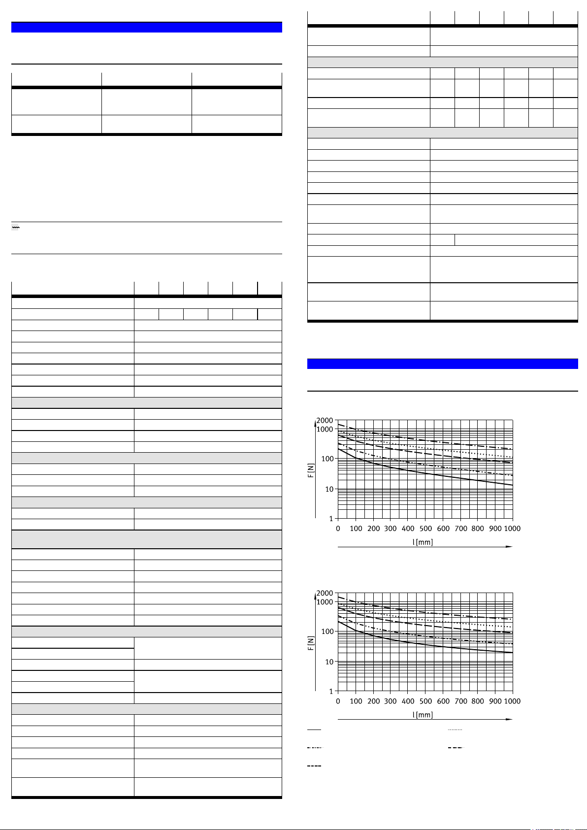
15.1 Max. permissible lateral forces for static applications
NOTICE!
In controlled operation, it may be necessary to adjust the max. lateral force to the
type of control.
Horizontal installation
Fig. 8
Vertical installation
Æ 100
Æ 125
Æ 160/200
Æ 250
Æ 320
Fig. 9

This manual suits for next models

6

Other Festo DC Drive manuals

Festo DFPD-HD S Series User manual

Festo

Festo DFPD-HD S Series User manual

Festo DGC-HD Series Parts list manual

Festo

Festo DGC-HD Series Parts list manual

Festo CMMT-ST-C8-1C-...-S0 Series User manual

Festo

Festo CMMT-ST-C8-1C-...-S0 Series User manual

Festo DGP-8 User manual

Festo

Festo DGP-8 User manual

Festo DGC 1H-PN Series User manual

Festo

Festo DGC 1H-PN Series User manual

Festo DFPI Series User manual

Festo

Festo DFPI Series User manual

Festo EMCS-ST User manual

Festo

Festo EMCS-ST User manual

Festo DGC-HD Series User manual

Festo

Festo DGC-HD Series User manual

Festo DNG Series Setup guide

Festo

Festo DNG Series Setup guide

Festo EMCA-EC-67 CO Series Reference guide

Festo

Festo EMCA-EC-67 CO Series Reference guide

Festo CMMT-AS-C2-11A-P3 S1 Series User manual

Festo

Festo CMMT-AS-C2-11A-P3 S1 Series User manual

Festo DGCI Series User manual

Festo

Festo DGCI Series User manual

Festo DGC-8 Series User manual

Festo

Festo DGC-8 Series User manual

Festo DGC-8 Series User manual

Festo

Festo DGC-8 Series User manual

Festo EMCA-EC-67-CO Series Reference guide

Festo

Festo EMCA-EC-67-CO Series Reference guide

Festo EMCA-EC-67 CO Series User manual

Festo

Festo EMCA-EC-67 CO Series User manual

Festo DFPI-***-***-ND2P-E-P-G2 User manual

Festo

Festo DFPI-***-***-ND2P-E-P-G2 User manual

Festo EMCA-EC-67 CO Series User manual

Festo

Festo EMCA-EC-67 CO Series User manual

Festo EMCA-EC-67 CO Series Operating and installation instructions

Festo

Festo EMCA-EC-67 CO Series Operating and installation instructions

Festo FKP Series User manual

Festo

Festo FKP Series User manual

Festo DAPS..R..-F Series User manual

Festo

Festo DAPS..R..-F Series User manual

Festo DFPI-xxx-ND2P-E-NB3 Series User manual

Festo

Festo DFPI-xxx-ND2P-E-NB3 Series User manual

Festo FDG-...-ZR-RF Series User manual

Festo

Festo FDG-...-ZR-RF Series User manual

Festo DGO A-B Series User manual

Festo

Festo DGO A-B Series User manual

Popular DC Drive manuals by other brands

Leadshine DM Series Hardware installation manual

Leadshine

Leadshine DM Series Hardware installation manual

ST X-CUBE-SPN12 user manual

ST

ST X-CUBE-SPN12 user manual

BeiJer BFI-H3 Start-up

BeiJer

BeiJer BFI-H3 Start-up

Rockwell Automation PowerFlex 755TM Original instructions

Rockwell Automation

Rockwell Automation PowerFlex 755TM Original instructions

Parker AC10 series Easy start guide

Parker

Parker AC10 series Easy start guide

Delta IED-S Series user manual

Delta

Delta IED-S Series user manual

IKEA TRADFRI ICPSHC24-10EU-IL-1 manual

IKEA

IKEA TRADFRI ICPSHC24-10EU-IL-1 manual

Danfoss VLT CDS 803 quick guide

Danfoss

Danfoss VLT CDS 803 quick guide

Control Techniques Commander SK Getting started guide

Control Techniques

Control Techniques Commander SK Getting started guide

Nidec F600 Step-by-step guide

Nidec

Nidec F600 Step-by-step guide

Seagate EXOS ST3000NM007A product manual

Seagate

Seagate EXOS ST3000NM007A product manual

Danfoss FC 100 Series Programming guide

Danfoss

Danfoss FC 100 Series Programming guide

Wittenstein cyber motor cyber reaction wheel 2 Planning guide

Wittenstein cyber motor

Wittenstein cyber motor cyber reaction wheel 2 Planning guide

Lenze L-force EYF Series Mounting instructions

Lenze

Lenze L-force EYF Series Mounting instructions

Johnson Controls York AYK550 user manual

Johnson Controls

Johnson Controls York AYK550 user manual

Minarik DC30-12-4Q-L manual

Minarik

Minarik DC30-12-4Q-L manual

Quantum LTO-3 quick start guide

Quantum

Quantum LTO-3 quick start guide

Parker E-DC Quick reference guide

Parker

Parker E-DC Quick reference guide

manuals.online logo
manuals.online logoBrands
  • About & Mission
  • Contact us
  • Privacy Policy
  • Terms and Conditions

Copyright 2025 Manuals.Online. All Rights Reserved.