ELFC-KF
6 Festo – ELFC-KF – 2017-02 English
6 Transport
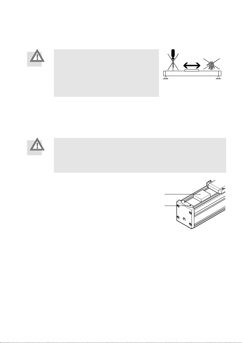
Note
Unexpected movement of components. The axis is unbraked and the carriage can move
freely.
Secure slide during transport.
Take product weight into account è13 Technical data.
Comply with maximum permitted support spacing when attaching transportation aids
è14 Characteristic curves.
7 Mounting
7.1 Preparation
Do not modify the screws and threaded pins.
Exception: immediate requirement for change by these operating instructions.
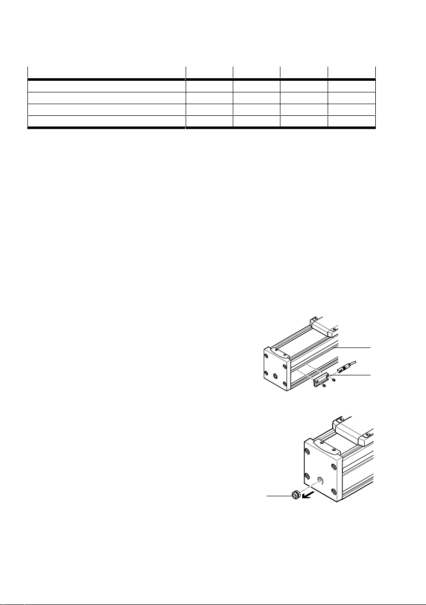
Place the product in such a way that its control sections are
accessible (e.g. band reversing).
Install product without tension or distortion.
Fasten product to a mounting surface with flatness of 0.05 %
of the stoke length, but max. 0.5 mm.
For gantry applications, attention must also be paid to parallel
alignment or product heights in alignment of the axes.
For additional information, contact your local Festo Service.
Take the required support clearances into consideration
è14 Characteristic curves.
Fig. 3
If the ELFC-KF guide axis is used in conjunction with a drive axis, e.g. ELGC-TB-KF:
Use mounting surfaces with identical evenness for both axes.
Use the same support spacing on the drive axis and on the guide axis. The guide axis is aligned by
moving the slide to the mounting points. Attach the guide axis when the slide with the transverse
connection is located in the area of the
attachment points. If necessary, use a connection with tolerance compensation (fixed bearing/mov
able bearing).
These measures prevent tension due to uneven deflection.