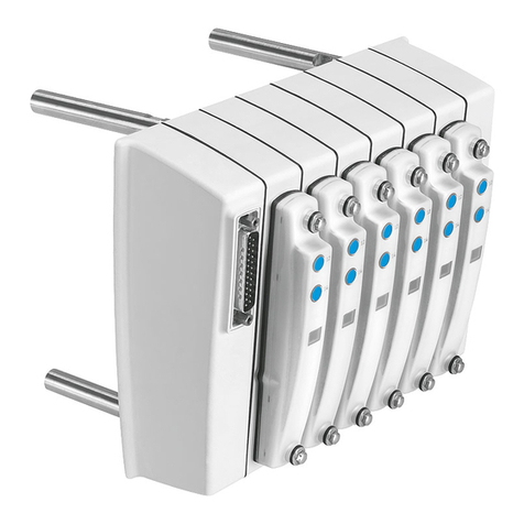
manuals.online logo
Brands
  1. Home
  2. •
  3. Brands
  4. •
  5. Festo
  6. •
  7. Touch Terminal
  8. •
  9. Festo VTEM User manual

Festo VTEM User manual

VTEM
Motion Terminal
Festo SE & Co. KG
Ruiter Straße 82
73734 Esslingen
Deutschland
+49 711 347-0
www.festo.com
Operating instructions
8179050
2022-06f
[8179052]
Translation of the original instructions
© 2022 all rights reserved to Festo SE & Co. KG
Chrome®, FIREFOX®, INTERNET EXPLORER®, MICROSOFT EDGE® are regis-
tered trademarks of the respective trademark owners in certain countries.
1About this document
1.1 Applicable documents
All available documents for the product è www.festo.com/sp.
Document Product Contents
Assembly instructions CPX, VTEM –
Manual VTEM System, function, parameteri-
sation
Manual GAMM-A... Motion App
Manual CPX terminal System
Application note VTEM Various contents
è www.festo.com/sp è VTEM
è Expert knowledge
Tab. 1: Applicable documents
1.2 Product version
This document refers to the following product versions:
Product Version
VTEM-… Motion Terminal VTEM from Revision 01
CTMM-S1-C Controller of the Motion Terminal VTEM from Revision 01
Firmware Firmware of the Controller CTMM from version 4.24.0
VEVM-S1-27-… Valve for Motion Terminal VTEM from Revision 01
CTMM-S1-D-8E-M8-3 Digital input module for Motion Terminal VTEM from revision 02
CTMM-S1-A-8E-A-M8-4 Analogue input module for Motion Terminal VTEM from revision 02
Browser1) –FIREFOX from version 38 (recommended)
–Chrome from version 64
–INTERNET EXPLORER from version 11
–MICROSOFT EDGE from version 38
1) Use current version.
Tab. 2: Product version
The product version can be identified from the product labelling or with the help
of appropriate Festo software.
Suitable software for determining the product version is available on the Festo
website è www.festo.com/sp.
Information on using the software can be found in the integrated Help function.
There may be an updated version of this document for this or later product
versions è www.festo.com/sp.
1.3 Product labelling
The product labelling is explained in the product manual è 1.1 Applicable docu-
ments.
2 Safety
2.1 Safety instructions
–Observe identification on the product.
–Before working on the product, switch off the power supply and secure it
against being switched on again.
–In the power-free status (normal position), compressed air may be trapped
between the working air ports and connected drives. To avoid accidental move-
ments of the connected drives due to leakage, carry out the following steps
before switching off the supply voltage:
–Bring the system into the exhausted state è App control (app control):
"Exhaust".
–Disconnect the compressed air supply and, if applicable, the vacuum supply.
–During rapid movement of heavy masses, especially during braking, the pres-
sure in the pneumatic system can increase and damage pneumatic compo-
nents.
–Set up the pneumatic installation with sufficient load reserve for the applica-
tion.
–Store the product in a cool, dry environment protected from UV and corrosion.
Keep storage times short.
–Comply with the handling specifications for electrostatically sensitive devices.
–Observe tightening torques. Unless otherwise specified, the tolerance is
± 20 %.
2.2 Intended use
The product is intended for controlling pneumatic drives and for implementing
motion tasks (Motion Apps).
The product may only be used as follows:
–Use only in an industrial environment: outside industrial environments, e.g.
in commercial areas and mixed commercial and residential areas, action to
suppress interference may be required.
–Use exclusively in combination with modules and components that are certified
for the specific product variant and have been tested and approved by Festo.
–Use in technically perfect original status without unauthorised modifications.
Only the conversions or modifications described in this and the further appli-
cable documents are permitted.
2.3 UL/CSA Certification
In combination with the UL inspection mark on the product, the information in this
section must also be observed in order to comply with the certification conditions
of Underwriters Laboratories Inc. (UL) for USA and Canada.
UL approval information
Product category code QUYX, QUYX7
File number E322346
Considered standards UL 61010-1
CAN/CSA C22.2 No. 61010-1
UL mark
Tab. 3
Only for connection to a NEC/CEC Class 2 supply.
WARNING
The unit shall be supplied by a power source which fulfils the requirements on a
limited-energy circuit in accordance to IEC/EN/UL/CSA 61010-1 or on a Limited
Power Source (LPS) in accordance to IEC/EN/UL/CSA 60950-1 or IEC/EN/UL/CSA
62368-1 or a Class 2 circuit in accordance to NEC or CEC.
3 Additional information
–Contact the regional Festo contact if you have technical problems
è www.festo.com.
–Accessories and spare parts è www.festo.com/catalogue.
4 Product overview
The product is a component of a CPX terminal, forms its pneumatic side, and is a
platform for execution of Motion Apps.
4.1 Structure
4.1.1 Product design
The product can consist of the following modules, depending on the configuration
ordered:
1 2 3 4 5
67
Fig. 1: Product design
1
CPX terminal electronics side
2
Controller Motion Terminal
CTMM-S1-C
3
Manifold rail
4
Input module CTMM-S1-A/D-…
(optional)
5
Pilot pressure regulator
6
Cover plate VABB-P11-27-T
(optional)
7
Valve slice VEVM-S1-27-…
The pressure regulator is set and sealed at the factory. This setting must not be
changed; doing so will invalidate the warranty.
4.1.2 Display components
This section describes the arrangement and function of the LEDs in the individual
modules. The meaning of the LED behaviour is described in è 10 Diagnostics.
4.1.2.1 Controller
1
2
Fig. 2: LED displays on the controller
1
CPX-specific LEDs
2
Ethernet-specific LED
LED Meaning
PL
(green)
Power Load Monitor load voltage supply UVAL
M
(yellow)
Modify Parameterisation mode (via CPX bus node or WebConfig
interface)
SF
(red)
System Failure Communication errors
PS
(green)
Power Functions Monitor operating voltage supply UEL/SEN
Tab. 4: CPX-specific LEDs
LED Meaning
TP
(green)
Ethernet Link/
Traffic
Ethernet connection/data traffic
Tab. 5: Ethernet-specific LED
4.1.2.2 Valve
1
Fig. 3: LED display on valve
1
LED display on valve (red/blue)
LED Meaning
(red) Valve faults: VTEM manual è 1.1 Applicable documents
(blue) Operation/update
Tab. 6: LED display on valve
4.1.2.3 Input modules
12
Fig. 4: LED displays of the input
modules
1
LED display for input status (green,
digital input modules CTMM-S1-D-...
only)
2
LED display for module error (red)
LED Meaning
(green) Input status (digital input modules CTMM-S1-D-… only)
P
(red)
Short circuit/overload
Tab. 7: LED display for input modules
4.1.3 Control elements
The product has no mechanical control elements. Parameters and setpoint values
are only set using the WebConfig interface or the higher-order controller. The Web-
Config interface can be opened with a web browser if there is an existing Ethernet
connection to the controller of the Motion Terminal è 8.1 Prior to commissioning.
4.1.4 Connecting elements
4.1.4.1 Connecting elements, electrical
1
Fig. 5: Functional earth connection
right
1
Functional earth connection
1
Fig. 6: Functional earth connection left
1
Functional earth connection (left-hand
end plate CPX terminal)
1
Fig. 7: Ethernet interface
1
Ethernet interface
Ethernet interface
The Ethernet interface is located on the controller behind a transparent cover
è Ensuring the degree of protection.
The Ethernet interface is used exclusively for accessing the WebConfig interface
for the controller è 8.1 Prior to commissioning.
When a connecting cable is connected to the Ethernet interface, electromagnetic
compatibility is not guaranteed.
Unauthorised access to the device can cause damage or malfunctions.
When connecting the device to a network:
Protect the network against unauthorised access.
Measures to protect the network include:
• Firewall
• Intrusion Prevention System (IPS)
• Network segmentation
• Virtual LAN (VLAN)
• Virtual private Network (VPN)
• Security at physical access level (port security)
For additional information è Guidelines and standards for security in information
technology, e. g. IEC 62443, ISO/IEC 27001.
Input modules
CTMM-...-D-... CTMM-...-A-...
1 +24 V USEN 1 +24 V USEN
3 0 V USEN 2 Input
4 Input 3 0 V USEN
4 n. c.
Tab. 8: Pin allocation for input modules
4.1.4.2 Connection elements, pneumatic
Ports for compressed air supply (1) and common exhaust (3) are available both
on the controller and on the right-hand end of the manifold rail. The ports are
internally connected in each case and can be used alternately or in parallel.
When multiple valves are connected simultaneously, the dynamic pressure cre-
ated in the exhaust ducts or the pressure drop in the supply ducts can negatively
affect other applications. When multiple valves are switched simultaneously, pres-
surisation and exhaust are recommended on both sides for an optimised flow rate
and exhaust performance.
1
2
3
5
4
6 7
8
23
Fig. 8: Pneumatic ports
1
M7 port for pressure compensa-
tion (L)
2
G3/8 port for common exhaust/
vacuum (3)
3
G3/8 port for compressed air
supply (1)
4
G1/8 ports for working air (2)
5
M7 port for pilot exhaust air (84)
6
G1/8 ports for working air (4)
7
Selector for external pilot air or
blanking plugs for internal pilot
air M5
8
M5 port for external pilot air
(14) or blanking plugs for internal
pilot air
4.2 Function
The function scope of the Motion Terminal VTEM is dependent on the scope of
the licensed Motion Apps. For many Motion Apps, the number of licences required
is based on the desired number of valves on which the Motion App should run
simultaneously. Other Motion Apps, for example, Motion App GAMM-A1 “Direc-
tional control valve functions”, are licensed by default for all valves of the Motion
Terminal.
The parameterisation and behaviour of the Motion Apps can be defined by a
higher-order controller or the integrated WebConfig interface. The details are
described in the manuals for the Motion Terminal and the Motion Apps è 1.1
Applicable documents
Common resources for the entire Motion Terminal system are used for simulta-
neous operation of several Motion Apps. Resulting dependencies are described in
the Application Notes è 1.1 Applicable documents.
This product uses open-source software. A list of the licences used is contained in
the manual of the Motion Terminal è 1.1 Applicable documents.
4.2.1 Vacuum operation
Only specific Motion Apps are suitable for vacuum use. The Motion Terminal
is supplied with vacuum via the port (3) for common exhaust. Manual of the
corresponding Motion App è 1.1 Applicable documents.
4.2.2 Soft-start function
Certain motion apps are equipped with a soft-start function, which prevents
unbraked extending of a drive when cylinder chambers are exhausted. This func-
tion can cause a drive to first move in the opposite direction during system
start-up and before execution of a motion command.
Manual of the corresponding Motion App è 1.1 Applicable documents.
4.2.3 Internal and external pilot air supply
The product can be operated with internal or external pilot air, depending on
the configuration ordered. The configuration can also be changed at a later time
è 11.2 External/internal pilot air.
•The pressure at port (1) must be > 0.3 MPa (3 bar) for the internal pilot air
supply.
• The pressure at port (14) must be > 0.3 MPa (3 bar) for the external pilot air
supply.
Mixed operation with internal and external pilot air is not intended.
The pressure at port (1) is monitored by the device. If the pressure at port (1) is
less than 0.3 MPa (3 bar), an external pilot air supply of at least 0.3 MPa (3 bar)
is required; the negative pressure monitoring at (1) must be deactivated via the
corresponding CPX module parameter è 1.1 Applicable documents. The device
does not monitor the pressure for port (14).
4.2.4 Behaviour when not supplied with power (normal position)
The behaviour when not supplied with power depends on the valve type. The type
is noted as a letter on the top side of the valve. Product labelling in the manual for
the Motion Terminal VTEM è 1.1 Applicable documents.
Identification Meaning
C Working air ports (2) and (4) are blocked (normal
position) when not supplied with electric power
(normally closed).
Tab. 9: Identification of the valve slice
4.2.5 Storage of data
The controller stores data for use with the Motion Terminal (current stroke,
voltage, pressure, temperature, operating time, running performance of booster).
These data remain on the device and are not passed on in any form.
4.2.6 Input modules
Certain Motion Apps can evaluate digital or analogue sensor signals. The sensors
necessary for this are connected to the CTMM-S1-A/D input modules.
The inputs are evaluated only by the controller of the Motion Terminal. The states
of the inputs cannot be queried directly by the higher-order controller. However,
various Motion Apps in the active state provide the input signals for the higher-
order controller. Manual of the corresponding Motion Apps è 1.1 Applicable
documents.
5Transport and storage
•Observe specifications for environmental and storage conditions è 12 Tech-
nical data.
6 Assembly
•Assembly in accordance with the assembly instructions CPX, VTEM è 1.1
Applicable documents.
7 Installation
Ensuring the degree of protection
NOTICE
Damage due to penetration of moisture.
• To ensure the IP65 degree of protection, use cover caps, blanking plugs, and
inspection covers to seal off unused ports.
7.1 Installation, pneumatic
NOTICE
Pay attention to compressed air quality.
Damage to property or loss of function from lubricated compressed air.
• Operate product only with unlubricated compressed air.
•Observe the requirements for compressed air quality è Technical data.
NOTICE
Frozen condensate or moisture
Frozen condensate or moisture may damage the product due to operation at low
temperatures even though it is still within the critical limits.
•Install a drying unit to remove condensate and moisture.
NOTICE
Damage or malfunction due to pressure increase
Damage to the product from increased pressure in the pneumatic system due to
rapid movement of heavy masses, especially during braking operations.
•Set up the pneumatic installation with sufficient load reserve for the applica-
tion.
1. Push tubing into or over the connection of the tubing fitting up to the stop.
2. For lock ring fittings or barbed hose fittings:
Pull the lock ring or tubing clip over the tubing connection and tighten.
3. Seal unused ports with blanking plugs.
Ensure pressure compensation
• Release the pressure inside the Motion Terminal through the port (L).
In the spray-protection area
•Screw accompanying silencers into the ports (3), (84) and (L) and tighten
them hand-tight.
In the non-spray-protection area
• The exhaust air at each of the ports (3), (84) and (L) must be removed to a
spray-water-protected area through a fitting and a tube.
Connecting external pilot air
The product can be designed for operation with external pilot air, depending on
the operation.
• Connect the external pilot air supply to the port (14).
7.2 Installation, electrical
The electrical installation is divided into the installation of the electronics side of
the CPX terminal and installation of the Motion Terminal VTEM.
WARNING
Risk of injury due to electric shock.
• For the electric power supply, use PELV circuits that guarantee a reliable electric
disconnection from the mains network.
•Observe IEC 60204-1/EN 60204-1.
• Connect all circuits for the operating and load voltage supply.
NOTICE
Insecure condition through reduced immunity to interference due to long signal
lines.
• Observe maximum permitted signal line length è 12 Technical data.
7.2.1 Earthing
NOTICE
Malfunctions from electromagnetic interference because electromagnetic com-
patibility in accordance with EMC Directive was not ensured.
• Connect the product to the earthing potential with low impedance at the
intended connections as described below.
• Observe supplementary instructions in the CPX terminal manual è 1.1 Appli-
cable documents.
1. Connect the right connection of the functional earth directly to the connection
of the functional earth on the left end plate of the CPX terminal with low
impedance.
2. Connect the functional earth connection on the left end plate of the CPX
terminal with low impedance to the earth potential.
7.2.2 Installation of the CPX terminal
•Install the terminal in accordance with the CPX terminal manual è 1.1 Appli-
cable documents.
7.2.3 Installation of the sensor cables
NOTICE
Transmission faults due to sensor and power supply lines close to each other.
• To avoid transmission faults, do not install sensor cables close to and parallel
to power supply lines.
•Do not use open cables without terminals.
The requirements for the type (analogue/digital) of sensors are derived from the
specifications of the Motion Apps. Manual of the corresponding Motion App è 1.1
Applicable documents.
The sensor inputs are assigned to the Motion Apps (valves) by the WebConfig
interface or the higher-order controller.
8 Commissioning
The behaviour of the product during commissioning is largely determined by the
parameterisation of the bus node (fail safe, system idle mode, …).
•Observe information on parameterisation in the manual of the bus node
è 1.1 Applicable documents.
8.1 Prior to commissioning
CAUTION
Injury due to uncontrolled movement of the actuator technology as a result of
defective setpoint value specifications. Drive might travel to the end position
without braking.
• During parameterisation, observe the exact function of the setpoint value spec-
ifications used.
CAUTION
Damage due to uncontrolled movement of the actuator technology as a result of
using incorrect sensors. The drive cannot be controlled as intended.
• Use only sensors intended for use with the Motion Terminal VTEM.
NOTICE
Malfunction due to incomplete installation
• Place only a completely mounted and wired Motion Terminal into operation.
8.1.1 Parameterisation
CAUTION
Injury through unexpected movement of the actuator technology due to change
of signal statuses and parameters with the CPX-MMI, CPX-FMT, WebConfig
interface or the higher-order controller.
• Keep the range of action of the actuator technology clear.
• Proceed very carefully when parameterising or changing signal statuses.
• Observe the notes on “Force”, “Idle mode” and “Fail safe” in the CPX terminal
manual (P.BE-CPX-SYS-…) as well as in the manual for the CPX-MMI and in the
online help of the CPX-FMT.
The Motion Apps can be parameterised in two different ways:
–Parameterisation by the WebConfig interface of the controller
–Parameterisation by the controller using the cyclical process data
8.1.1.1 Parameterisation by the WebConfig interface of the controller
Factory settings of the controller:
IP address: 192.168.4.2, subnet mask: 255.255.0.0
Password: vtem
The password can be changed via the WebConfig interface.
The device on which the WebConfig interface is to be opened must be connected
directly to the Motion Terminal controller. The WebConfig interface for the con-
troller cannot be opened via the Ethernet connection of a bus node in the CPX
terminal.
1. To access the WebConfig interface, establish a connection to the Ethernet
interface of the Motion Terminal controller.
2. Change the IP address and subnet mask of the device used to access the
WebConfig interface to the IP address and subnet mask of the controller.
3. Start the browser and enter the IP address of the controller into the address
line.
4. Use the WebConfig interface (“Configuration” button) for parameterisation of
the Motion Apps for the individual valves.
5. After parameterisation, disconnect the Ethernet interface of the controller to
ensure electromagnetic compatibility.
6. Re-assemble the transparent cover cap of the Ethernet interface to ensure the
degree of protection.
To save the parameterisation permanently on the controller, even with the power
supply switched off, run the corresponding function of the WebConfig interface.
Operation of the WebConfig interface is described in the “Motion Terminal VTEM,
WebConfig interface” QuickGuide è 1.1 Applicable documents.
8.1.1.2 Parameterisation via the controller
Parameterisation via the controller is described in the product manual and in the
CPX terminal manual è 1.1 Applicable documents.
8.2 During commissioning
CAUTION
Injury due to unexpected movement during testing of the product function with
actuator technology and persons in the field of action.
• Keep the range of action of the actuator technology clear.
CAUTION
Injury due to sudden movement of the actuator technology due to pressure
build-up that is delayed or too slow.
• If a safety switch valve is used, the Motion Terminal is operated with external
pilot air, which is branched off before the safety switch valve.
9 Maintenance
9.1 Regular maintenance and repair work to be carried out
Area Interval Action
Housing and
mechanical
system
every six
months
Check the relevant tightening torque of the following parts:
–Tie rods
–Retaining screws of the modules
–Mounting screws
Electrical every six
months
Check the following:
–Tightening torques for screws of the earthing conductor
–Correct seating of all plugs
–Tightening torque of the cable connectors
Tab. 10: Maintenance and repair work
9.2 Clean/replace silencers
NOTICE
Malfunction due to pressure rise in the exhaust ducts due to contamination of
the silencers.
• Clean yellow/black discoloured silencers with petrol or benzene, or replace
them.
9.3 Replace valve or input module
NOTICE
Damage to the product due to replacement of components with compressed air,
operating voltage and load voltage supply switched on (UEL/SEN, UVAL).
• Prior to replacing components, switch off the compressed air, operating voltage
and load voltage supply (UEL/SEN, UVAL).
1. Unscrew retaining screws of the module.
2. Pull module upward and off the supply plate.
3. Place new module straight from above into the supply plate.
4. Screw the module on at first only lightly, and then tighten with the correct
tightening torque è 11.1 Tightening Torques.
10 Diagnostics
Diagnostics are described in this chapter using the LED displays of the Motion
Terminal. Additional diagnostics options è VTEM manual è 1.1 Applicable docu-
ments.
10.1 LEDs on the controller
LED PL (green) Meaning Measure
lights
Voltage is present. No error. –
off
No voltage present. Check connection of the power
supply.
Tab. 11: LED PL display (power load, load voltage supply)
LED M (yellow) Meaning Measure
lights
Configuration active: the Web-
Config interface has write
access, or the PLC is executing
write access on the parameteri-
sation of the controller.
–
flashes
Option for using demo licences
active.
Note the time remaining for the
demo period
off
Configuration inactive: no
access via the WebConfig inter-
face.
–
Tab. 12: LED display M (Modify)
LED PS (green) Meaning Measure
lights
Voltage is present. No error. –
flashes
Voltage is present but outside
the tolerance range.
Rectify short circuit/overload.
off
No voltage present. Check connection of the power
supply.
Tab. 13: LED display PS (power system, operating voltage supply)EL/SEN)
LED SF (red) Meaning Measure
off
No error –
lights
Voltage of the load voltage
supply UVAL is outside the toler-
ance range.
Rectify short circuit/overload.
Access to WebConfig interface
is not possible or only condition-
ally.
Error on the WebConfig user
interface or read and remedy via
PLC, CPX-FMT or FFT.
Tab. 14: LED display SF (system failure)
LED TP (green) Meaning Measure
lights
Network connection is OK (link) –
flashes
Data traffic (traffic) flashing fre-
quency is dependent on the
traffic.
–
off
No network connection/network
cable is not connected.
If access to the WebConfig inter-
face is required:
Check network connection
Tab. 15: LED display TP (Ethernet link/traffic)
10.2 LED on valve
LED valve (blue/red) Meaning Measure
red light
Valve faults Check error log. VTEM manual
è 1.1 Applicable documents.
Load voltage supply UVAL not
applied.
Check connection of the power
supply UVAL.
blue light
Error-free operation –
blue
flashing
Update –
Valve boots –
off
Valve has no power supply. If the power supply of the ter-
minal is switched on, switch off
power supply and check valve to
ensure it is seated properly.
Tab. 16: LED display on valve
10.3 LED on analogue input module
LED P (red) Meaning Measure
off
No error –
lights
Short circuit/overload in sensor
supply.
Rectify short circuit/overload.
Module error Switch operating supply voltage
UEL/USEN off and back on.
Tab. 17: LED display module error
10.4 LEDs on digital input module
LED P(red) Meaning Measure
off
No error –
lights
Short circuit/overload in sensor
supply.
Rectify short circuit/overload.
Module error Switch operating supply voltage
UEL/USEN off and back on.
Tab. 18: LED display module error
LED (green) Meaning Measure
lights
Logic 1 (signal is pending). –
off
Logic 0 (signal not pending). –
Tab. 19: LED display input status
11 Modification
11.1 Tightening Torques
1
2
3
4
5
6
Fig. 9: Tightening Torques
10.4 Nm ± 10 %
21.5 Nm ± 20 %, ß PZ 2
3Hand-tight (cover caps 8x)
42.0 Nm ± 20 %
51.5 Nm - 30 %
64.0 Nm ± 20 % (connection of con-
troller/valve terminal)
11.2 External/internal pilot air
11.2.1 Configuration for internal pilot air
1
2
Fig. 10: Internal pilot air
1
Sealing plug at the external pilot air
port (14)
2
Sealing plug
11.2.2 Configuration for external pilot air
1
2
Fig. 11: External pilot air
1
Fitting at the external pilot air port (14)
2
Selector
12 Technical data
12.1 Technical data, general
Permitted temperature ranges
Storage [°C] –20 … +40
Environment [°C] 5 … 50
Medium [°C] 5 … 50
Tab. 20: Temperature ranges
Environmental conditions
Degree of protection IP651)
Relative humidity [%] 0 … 90
Vibration and shock resistance è Assembly instructions CPX-VTEM
1) Fully assembled and unused connections sealed. IP65 degree of protection is not ensured when using the
Ethernet port.
Tab. 21: Environmental conditions
Note on materials
PWIS Contains paint-wetting impairment sub-
stances1)
1) PWIS = paint-wetting impairment substances
Tab. 22: Note on materials
12.2 Technical data, pneumatic
Characteristic valve values
Switching time on [ms] 8.5
Switching time off [ms] 8.5
C value [l/s*bar] 2
Standard nominal flow rate
Pressurisation
(6 bar against 5 bar)
[l/min] 450
Standard nominal flow rate
Exhaust port
(6 bar against 5 bar)
[l/min] 480
Direction of flow not reversible
Tab. 23: Characteristic valve values
Pressure characteristics and media characteristics
Operating medium, control medium Compressed air in accordance with ISO
8573-1:2010 [7:4:4]
inert gases
Information on operating medium, con-
trol medium
Lubricated operation not possible
Vacuum operation Only at the exhaust ports (3)
Valve terminal total leakage [l/h] 15 plus leakage of valve slots
Leakage per valve slot [l/h] 3 (with valve)
1 (with blind plate)
[bar] [MPa]
Nominal operating pressure/nominal
pilot pressure
6 0.6
Operating pressure, pilot pressure
with external pilot air via port (14)
0 … 8 0 … 0.8
Operating pressure, pilot pressure
with internal pilot air via port (1)
3 … 8 0.3 … 0.8
Tab. 24: Pressure characteristics and media characteristics
Port patterns
Working air ports (2) and (4) G 1/8
Pilot air (14) M5
Valve ports (1) and (3) G 3/8
Pilot exhaust air (84) M7
Pressure compensation (L) M7
Tab. 25: Port patterns
12.3 Technical data, electrical
Power supply
Operating voltage (via CPX terminal)
Voltage range [V DC] 18 … 30
Nominal voltage [V DC] 24
Electrical isolation UEL/SEN and UVAL Yes, with separate supply at the CPX ter-
minal
Intrinsic current consumption VTEM at 24 V DC typ.
via UEL/SEN via UVAL
Controller + linkage [mA] 115 85
Per valve [mA] 28 24
Analogue input module (plus intrinsic
consumption of the sensors)
[mA] 12 0
Digital input module (plus intrinsic con-
sumption of the sensors)
[mA] 12 0
Functional earth (FE)
Via functional earth connection of the CPX terminal and functional earth connection at the VTEM
terminal strip
Tab. 26: Power supply
Approvals
CE marking in accordance with EU EMC Direc-
tive1)
See declaration of conformity
è www.festo.com/sp
1) The device is intended for use in an industrial environment. Measures for interference suppression may be
required in residential areas.
Tab. 27: Approvals
12.4 Technical data, input modules
General
Maximum length of the connected
cables
[m] 30
Electrical protection Internal electronic fuse per module
Galvanic isolation between the inputs None
Tab. 28: General
Digital input module CTMM-…-D-…
Interface M8, 3-pin
Behaviour Voltage input 24 V DC
Input characteristic In accordance with IEC 61131-2, type 3
Switching logic PNP, NO (normally open)
Switching level
Signal 0 [V DC] £ 5
Signal 1 [V DC] ³ 11
Tab. 29: Digital input module
Analogue input module CTMM-…-A-…
Interface M8, 4-pin
Behaviour Current input 4 … 20 mA
Tab. 30: Analogue input module
12.5 Technical data for UL/CSA certification
Electrical data and ambient conditions UL/CSA
Input current max. 0.44 A
Power max. 10.6 W
Pressure differential max. 0.8 MPa
Pollution degree 2
Humidity range 0 … 90 %
Installation site for indoor use only
Max. installation height 2000 m
Degree of protection The degree of protection IP65 is not UL-tested.
Tab. 31: Electrical data and ambient conditions UL/CSA

Other manuals for VTEM

7

Other Festo Touch Terminal manuals

Festo CPV-GE-ASI-8E6A-Z Series Parts list manual

Festo

Festo CPV-GE-ASI-8E6A-Z Series Parts list manual

Festo VTOP User manual

Festo

Festo VTOP User manual

Festo CPX User manual

Festo

Festo CPX User manual

Festo CPX-FB14 User manual

Festo

Festo CPX-FB14 User manual

Festo VTEM Operating and installation instructions

Festo

Festo VTEM Operating and installation instructions

Festo IFB05-03 User manual

Festo

Festo IFB05-03 User manual

Festo CPX-CMXX Parts list manual

Festo

Festo CPX-CMXX Parts list manual

Festo CPX-FB23 User manual

Festo

Festo CPX-FB23 User manual

Festo CPX Series User manual

Festo

Festo CPX Series User manual

Festo VTSA-F-CB User manual

Festo

Festo VTSA-F-CB User manual

Festo CPV10-GE-IBL-8 User manual

Festo

Festo CPV10-GE-IBL-8 User manual

Festo VTSA-F-CB Assembly instructions

Festo

Festo VTSA-F-CB Assembly instructions

Festo VTSA ASI-8E8A-Z Series Parts list manual

Festo

Festo VTSA ASI-8E8A-Z Series Parts list manual

Festo CPX-FB13 User manual

Festo

Festo CPX-FB13 User manual

Festo VRUG-PT-L User manual

Festo

Festo VRUG-PT-L User manual

Festo CPX-MMI-1 User manual

Festo

Festo CPX-MMI-1 User manual

Festo MPA-FB Series User manual

Festo

Festo MPA-FB Series User manual

Festo CPX Series User manual

Festo

Festo CPX Series User manual

Festo CPV -VI Series User manual

Festo

Festo CPV -VI Series User manual

Festo VIFB13-02 Series User manual

Festo

Festo VIFB13-02 Series User manual

Festo CPX Series User manual

Festo

Festo CPX Series User manual

Festo CPX-FB13 User manual

Festo

Festo CPX-FB13 User manual

Festo CPX Series User manual

Festo

Festo CPX Series User manual

Festo CPX Series User manual

Festo

Festo CPX Series User manual

Popular Touch Terminal manuals by other brands

ZKTeco LockerPad-7B user manual

ZKTeco

ZKTeco LockerPad-7B user manual

First Data VeriFone VX 680 Quick setup guide

First Data

First Data VeriFone VX 680 Quick setup guide

Infinite Peripherals Infinea mPOS Plus user manual

Infinite Peripherals

Infinite Peripherals Infinea mPOS Plus user manual

Partner PT-9000 user manual

Partner

Partner PT-9000 user manual

AML M7220 quick start guide

AML

AML M7220 quick start guide

Digital Electronics Corporation Pro-face GLC2300 user manual

Digital Electronics Corporation

Digital Electronics Corporation Pro-face GLC2300 user manual

Toshiba ST-71 SERIES owner's manual

Toshiba

Toshiba ST-71 SERIES owner's manual

Newland NL-8510 POS user manual

Newland

Newland NL-8510 POS user manual

EMS Ingenico Desk/5000 manual

EMS

EMS Ingenico Desk/5000 manual

Poindus VariPOS 715S user manual

Poindus

Poindus VariPOS 715S user manual

Symbol PDT 7500 Series manual

Symbol

Symbol PDT 7500 Series manual

Bosch Rexroth IndraControl VCP 35.2 Project planning manual

Bosch

Bosch Rexroth IndraControl VCP 35.2 Project planning manual

Pidion BIP-5000 manual

Pidion

Pidion BIP-5000 manual

GAI-Tronics 9974 manual

GAI-Tronics

GAI-Tronics 9974 manual

Rockwell Automation Allen-Bradley PanelView 800 HMI installation instructions

Rockwell Automation

Rockwell Automation Allen-Bradley PanelView 800 HMI installation instructions

Feig Electronic ID MAX50.10-E Installation

Feig Electronic

Feig Electronic ID MAX50.10-E Installation

Hytera TETRA owner's manual

Hytera

Hytera TETRA owner's manual

FlexKom POS 4S Installation

FlexKom

FlexKom POS 4S Installation

manuals.online logo
manuals.online logoBrands
  • About & Mission
  • Contact us
  • Privacy Policy
  • Terms and Conditions

Copyright 2025 Manuals.Online. All Rights Reserved.