Fike SHP 10-051 User manual

Product Manual
Conventional
Fire Alarm/Suppression
System
Manual P/N: 06-130
Rev. No: 3, 04/02
P/N: 10-051
firealarmresources.com

firealarmresources.com

FIKE CORPORATION
UL S2203 SHP Product Manual Page i
FM 0Z8A0.AY Manual P/N: 06-130 Rev. No. 3, 04/02
Fike Corporation - Offices
Copyright Information
This document may not be reproduced, in whole or in part, by any means without the prior express written
permission of Fike Corporation.
Fike
is a registered trademark of Fike Corporation.
Disclaimers
The information contained in this manual is as accurate as currently possible. This manual is intended to
be an aid to Fike authorized sales outlets, who have been trained in an approved manner by Fike, and
the user who is a customer of the Fike authorized sales outlet. Fike does not warrant that this manual is
technically correct, complete, or free from writing problems or that the Fike products referenced therein
are free from minor flaws.
In accordance with our policy of continuing product and system improvement, Fike reserves the right to
change designs or specifications without obligation and without further notice.
Reader Responses
Fike encourages input from our sales outlets and end users on how we can improve this manual and the
products themselves. Please direct all calls of this nature to Fike’s Product Support Department
at (816) 229-3405.
Any communication received becomes the property of Fike Corporation.
Warranties
Fike provides a one-year limited manufacturer's warranty on this product. The standard warranty is printed
in each Marketing Price List. All warranty returns must be returned from an authorized Fike Sales outlet.
Contact Fike's Marketing Department for further warranty information. Fike maintains a repair department
that is available to repair and return existing electronic components or exchange/purchase previously
repaired inventory component (advance replacement). All returns must be approved prior to return. A
Material Return Authorization (MRA) number should be indicated on the box of the item being returned.
Contact the appropriate Regional Sales Manager for further information regarding Material Return
Procedures.
Fike Corporation
World Headquarters
704 South 10th Street
P.O. Box 610
Blue Springs, Missouri 64013
U.S.A.
Ph: (816) 229-3405
Fax: (816) 229-5082
Fike Canada
4140 Morris Drive
Burlington, Ontario L7L 5L6
Canada
Ph: (905) 681-3100
Fax: (905) 681-3107
Fike Europe
Toekomstlaan 52
B-2200 Herentals
Belguim
Ph: 011-32-14-210031
Fax: 011-32-14-210743
Fike Latina
Avenida Paulista 2202, 3°, cj34
Cerqueira Cesar, Sao Paulo
Brazil, CEP 01310-300
Ph: 011-55-11-251-5244
Fax: 011-55-11-284-8479
Fike United Kingdom
10-11 Enterprise Estate
Moorfield Road
P.O. Box 540
Guildford, Surrey GU1 1RB
United Kingdom
Ph: 011-44-8700-777-540
Fax: 011-44-7000-777-540
Fike Singapore PTE. LTD.
30, Loyang Way #01-09
Loyand Industrial Estate
Singapore, 509769
Singapore
Ph: 011-65-545-7989
Fax: 011-65-545-6689
firealarmresources.com

firealarmresources.com

FIKE CORPORATION
UL S2203 SHP Product Manual Page ii
FM 0Z8A0.AY Manual P/N: 06-130 Rev. No. 3, 04/02
TABLE OF CONTENTS
Section Page
1.0 Preface................................................................................................................................................... 1
1.1 About This Manual .............................................................................................................. 1
1.2 Product Support .................................................................................................................. 1
1.3 Revision History .................................................................................................................. 1
1.4 Terms Used in this Manual .............................................................................................. 1-3
1.5 Symbols Used in this Manual.............................................................................................. 4
1.6 Safety Notices ..................................................................................................................... 4
2.0 Product Overview ................................................................................................................................ 5
2.1 Product Description............................................................................................................. 5
2.2 Listings and Approvals ........................................................................................................ 5
2.3 Agency Standards and Compliance................................................................................. 5-6
2.4 Related Documentation.......................................................................................................6
2.5 SHP Features...................................................................................................................... 7
3.0 Equipment/Products............................................................................................................................. 9
3.1 Main Panel Hardware..................................................................................................... 9-10
3.2 Input Devices ...............................................................................................................11-12
3.3 Output Devices.................................................................................................................. 12
3.4 Ancillary Devices............................................................................................................... 13
3.5 Spare Parts ....................................................................................................................... 14
3.6 Specifications ............................................................................................................... 15-18
3.7 Enclosure Specifications ................................................................................................... 19
4.0 Installation........................................................................................................................................... 21
4.1 Enclosure Installation ........................................................................................................ 21
4.2 Power and Field Wiring..................................................................................................... 22
4.3 Wiring Verification ............................................................................................................. 23
4.4 System Module Installation ............................................................................................... 23
4.5 System Configuration........................................................................................................ 23
4.6 Wiring Diagrams........................................................................................................... 24-25
4.7 Circuit Configuration..................................................................................................... 26-27
4.8 Initial Power-Up................................................................................................................. 28
4.9 Complete Field Wiring....................................................................................................... 28
4.10 Checkout System .............................................................................................................. 28
4.11 Releasing Hardware..........................................................................................................28
5.0 Operations ........................................................................................................................................... 29
5.1 User Switch Interaction ..................................................................................................... 29
5.2 Diagnostic LED Code Designators ................................................................................... 29
5.3 Silencing Rules ................................................................................................................. 29
5.4 Outputs Disabled Mode..................................................................................................... 30
5.5 Supervisory and Trouble Status LED’s ............................................................................. 30
5.6 Latching versus Non-Latching Troubles ........................................................................... 30
5.7 Waterflow Alarm Operations ............................................................................................. 30
5.8 Supervision Response Times ........................................................................................... 30
5.9 Low Power Conditions ...................................................................................................... 30
5.10 Alarm Operation (Suppression Mode) .............................................................................. 31
5.11 Alarm Operation (Sprinkler Mode) .................................................................................... 32
5.12 Supervisory Operation ...................................................................................................... 32
5.13 Trouble Operation ............................................................................................................. 32
firealarmresources.com

FIKE CORPORATION
Page iii SHP Conventional Fire Suppression Panel UL S2203
Rev. No: 3, 04/02 Manual P/N: 06-130 FM 0Z8A0.AY
6.0 Servicing .............................................................................................................................................. 33
6.1 Checkout ........................................................................................................................... 33
6.2 Maintenance...................................................................................................................... 33
6.3 Troubleshooting ........................................................................................................... 33-36
Appendix 1 ................................................................................................................................................. 37
Battery Calculations .................................................................................................................. 37-38
Appendix 2 ................................................................................................................................................. 39
ULC Operation ............................................................................................................................... 39
Appendix 3 ................................................................................................................................................. 41
System Operation Posting ............................................................................................................. 41
Index ........................................................................................................................................................... 43
firealarmresources.com

FIKE CORPORATION PREFACE
UL S2203 SHP Product Manual Page 1 of 43
FM 0Z8A0.AY Manual P/N: 06-130 Rev. No. 3, 04/02
1.0 PREFACE
1.1 ABOUT THIS MANUAL
This manual is intended to be a complete reference for the installation, operation, and service of the Fike
Single Hazard Panel (SHP) Fire Alarm/Suppression Control System. The information contained in this
manual must be utilized by the factory trained Fike sales outlet in order to properly install, test and service
the SHP. This manual can also be used by the end user as an Operations Manual for the SHP.
Before you refer to any section in this manual, and before you attempt to install or use the SHP, be sure
to read the important safety notices in section 1.6.
This manual is divided into sections for easy reference. The first-time installer and/or user should
thoroughly read and understand the instructions contained within this manual before using this device.
These instructions must be followed to avoid possible damage to the SHP itself or adverse operating
conditions caused by improper installation and programming.
1.2 PRODUCT SUPPORT
If you have a question or encounter a problem not covered in this manual, you should first try to contact
the sales outlet that installed the protection system. Fike has a worldwide distribution network. Each
sales outlet sells, installs, and services Fike equipment. Look on the inside door, left side, there should
be a sticker with an indication of the sales outlet who sold the system. If you can not locate the sales
outlet, please call Fike Customer Service for locating your nearest sales outlet, or go to our web-site at
www.fike.com. If you are unable to contact your installing sales outlet or you simply do not know who
installed the system you can contact Fike Product Support at (816) 229-3405, Monday through Friday,
8:00 a.m. to 5:00 p.m. CST.
1.3 REVISION HISTORY
Document Title: SHP Conventional Fire Alarm/Suppression System Product Manual
Document Reorder Number: 06-130
Revision Section Date Reason for Change
0 All Sections 06/12/96 Initial Release
1 All Sections 11/02/99 ULC Additions
2 All Sections 12/01/01 Product Update
3 Section 4.6, 6.3.1 04/02 Added wiring and correct
1.4 TERMS USED IN THIS MANUAL
The following are various terms used in this manual with a brief description of each:
Term Description
Ω
ΩΩ
ΩSymbol for “ohm”. Unit of resistance.
AC Normal State (“AC Normal” Green LED ON) The system is in the AC Normal state when
appropriate AC power is being applied to the system.
Abort An input to a suppression system to prevent an unwanted discharge of fire
suppressant agent. The SHP has several different abort types.
Alarm State (“Alarm” Red LED ON, Piezo pulsing) The alarm occurs when an input circuit
configured for alarm operation has been activated. Activation typically
initiated by a detector or contact device. The system leaves the alarm state
upon entry into the pre-discharge or release state.
firealarmresources.com

PREFACE FIKE CORPORATION
Page 2 of 43 SHP Product Manual UL S2203
Rev. No: 3, 04/02 Manual P/N: 06-130 FM 0Z8A0.AY
Class A wiring Input circuits capable of transmitting an alarm signal during a single open or a
non-simultaneous single ground fault on a circuit conductor shall be
designated as Style D or Class A. Similarly, output circuits capable of
activating during a single open or a non-simultaneous ground fault on a circuit
conductor shall be designated as Style Z or Class A. Commonly referred to
as redundant or 4-wire connection; this manual refers to 4-wire connections
as Class A wiring.
Class B wiring Input circuits incapable of transmitting and alarm signal beyond the location of
the fault condition (listed for Class A wiring above) shall be designated as
Style B or Class B. Similarly, output circuits incapable of operating beyond
the location of the fault condition shall be designated as Style Y or Class B.
This manual refers to 2-wire connections as Class B wiring
Cross-zone Detection A detection scheme where two detectors must activate before the system
enters into the pre-discharge state; at least one detector from each detection
initiating circuit must be active.
Initiating Device A system component that originates transmission of a change-of-state
condition, such as in a smoke detector, manual fire alarm box, or supervisory
switch. This manual interchanges the terms initiating device and input device.
Initiating Device Circuit A circuit to which automatic or manual initiating devices are connected where
the signal received does not identify the individual device operated. This
manual interchanges the terms initiating device circuit and input circuit.
Normal State (“Trouble” Yellow LED OFF) The system is in the normal state when the
power supply and all circuits are configured properly, connected, and
responding properly. The system remains in normal state until a trouble
condition occurs.
Notification Appliance A fire alarm system component such as a bell, horn, speaker, light, or textual
display that provides audible, tactile, or visible output, or any combination
thereof. The device notifies building occupants of system status. This
manual interchanges the terms notification and audible appliance.
Notification Appliance
Circuit
A circuit or path directly connected to a notification appliance(s). This manual
interchanges the terms notification appliance circuit and audible circuit.
Non Power-Limited A circuit designation given for wiring purposes. The amount of current flowing
through the circuit is unlimited vs. being limited, or power-limited. AC power
and Battery wiring is Non Power-limited.
Power-Limited A circuit designation given for wiring purposes. The amount of current flowing
through the circuit is limited (typically by fuse) vs. being unlimited, or non-
power limited. The SHP input and output circuits are power limited. The
circuit has a maximum power that flows through it or it current limits and
opens.
Pre-discharge Delay The time (in seconds) that the system will delay entering the release state
after the zone’s detection type has been satisfied. Activation of an abort
switch will have an effect on this value, depending upon the abort type
selected.
Pre-discharge State (“Alarm” Red LED ON, Piezo chirping) The pre-discharge state occurs when
the zone’s detection type input conditions are satisfied (Cross Zone
Detection, Sequential Alarm Detection, or Single Detector Release). Upon
time delay countdown completion (unless delayed by a pertinent activated
abort input), the system leaves the pre-discharge state and enters the release
state.
Release State (“Alarm” Red LED ON, Piezo chirping) The release state occurs upon
completion of the pre-discharge state or upon activation of a manual release
input. At the start of the release state, output circuits configured for releasing
shall operate.
firealarmresources.com

FIKE CORPORATION PREFACE
UL S2203 SHP Product Manual Page 3 of 43
FM 0Z8A0.AY Manual P/N: 06-130 Rev. No: 3, 04/02
Sequential Detection A detection scheme where the sum total of active detectors on the initiating
circuits must be two or more before the system will enter the pre-discharge
state.
Single Detector Release
Detection
A detection scheme where activation of one detector causes the system to
enter the pre-discharge state. SDR (Single Detector Release) detector(s) are
installed on initiating circuits setup for sequential detection.
Solenoid On Time The time (in minutes) that the solenoid is activated upon entering the release
state. Reset of the system overrides this value.
Supervisory State (“Supervisory” Yellow LED ON, Piezo Warble) The supervisory state occurs
upon activation of a supervisory input circuit. The supervisory state is non-
latching and will follow the status of the supervisory input contact.
Trouble State (“Trouble” Yellow LED ON, Piezo Constant) The trouble state occurs upon
any detectable condition which could impair system operation including
connection problems, ground faults, hardware problems, power problems,
configuration problems, or prematurely activated abort inputs. Certain trouble
conditions are latching; others allow the system to reset upon trouble
condition removal. Depending upon the type of trouble condition, the system
may or may not remain operational. When the system is in trouble state, it is
not in the normal state.
firealarmresources.com

PREFACE FIKE CORPORATION
Page 4 of 43 SHP Product Manual UL S2203
Rev. No: 3, 04/02 Manual P/N: 06-130 FM 0Z8A0.AY
1.5 SYMBOLS USED IN THIS MANUAL
The following symbols are used throughout this manual.
NOTE: Used to call your attention to an important procedure, function or operational
procedure.
CAUTION: Used to identify functions or procedures of utmost importance.
WARNING: Used to identify functions and/or procedures that could cause property damage
or personal injury if the procedures identified in this manual are not followed.
1.6 SAFETY NOTICES
Be certain to read all the following warnings and cautions before installing or using this device.
Accidental damage to the device could result if these warnings and cautions are not heeded!
CAUTION: The SHP contains static sensitive components. Handle the electronics by
the edges only and avoid touching the integrated components. Keep the
electronics in the protective static bags it was shipped in until time for
installation. Always ground yourself with a proper wrist strap before handling
the module(s). If the installer is grounded at all times, damage due to static
discharge will not occur. If the module requires repair or return to Fike, it
must be shipped in an anti-static bag.
CAUTION: To ensure proper system operation after installation of the SHP, this device
must be tested in accordance with NFPA 72 - 1999 edition. Re-acceptance
testing is required after any change, addition or deletion of system
components, or after any modification, repair or adjustment to system
hardware or wiring.
WARNING: Failure to disconnect power to the releasing circuit(s) and disarm the
solenoid(s) or any other "critical operation" contacts prior to system testing
may cause accidental activation of the system.
firealarmresources.com

OVERVIEW FIKE CORPORATION
UL S2203 SHP Product Manual Page 5 of 43
FM 0Z8A0.AY Manual P/N: 06-130 Rev. No. 3, 04/02
2.0 PRODUCT OVERVIEW
2.1 PRODUCT DESCRIPTION
The Fike SHP (P/N 10-051) is a compact, cost-effective, conventional fire alarm and suppression
releasing panel. The SHP is designed for use with Fike Clean Agent Fire Suppressant, CO2, or sprinkler
(pre-action/deluge) suppression systems. The SHP controller is shipped from the factory pre-configured
for Clean Agent suppression operation.
The main controller contains all electronics required for a complete detection and control system suitable
for most applications. Optional modules, which plug into the main circuit board, are available to add
increased functionality to the system.
2.2 LISTINGS AND APPROVALS
Approval Agency File Number
Underwriters Laboratories S2203
Type: Local, Remote Station, Central Station PPU
Service Type: A-Automatic Fire Alarm, M-Manual Fire Alarm
WF-Water-flow alarm, SS-Sprinkler Supervisory Service,
Releasing, DACT
Type Signaling: Non-coded
Underwriters Laboratories of Canada (ULC) CS401/CS770-25168, 25169
Factory Mutual (FM) OZ8A0.AY
California State Fire Marshall (CSFM) 7165-0900:114
City of New York (MEA) 126-96-E
2.3 AGENCY COMPLIANCE AND STANDARDS
This Fire Alarm Control Panel complies with the following NFPA, UL, and ULC standards:
NFPA 72 – National Fire Alarm Code
UL 864 – Standard for Control Units for Fire Protective Signaling Systems
CAN/ULC S527 – Standard for Control Systems for Fire Alarm Systems
Smoke and Thermal
Detectors
Waterflow and Sprinkler
Supervisory
Manual Fire Alarm
or
Manual Releasing
and Abort
Stations
Audible and Visual
Alarm Signals
HVAC and Equipment
Shutdown
Sprinkler
Preaction
Clean Agent
Release
firealarmresources.com

OVERVIEW FIKE CORPORATION
Page 6 of 43 SHP Product Manual UL S2203
Rev. No: 3, 04/02 Manual P/N: 06-130 FM 0Z8A0.AY
The installer should also be familiar with the following documents and standards:
National Fire Protection Association (NFPA) Codes:
NFPA 12 – Carbon Dioxide Extinguishing Systems (High Pressure Only)
NFPA 12A – Halon 1301 Extinguishing Systems
NFPA 13 – Sprinkler Systems
NFPA 15 – Water Spray Fixed Systems
NFPA 16 – Deluge, Foam-water and Foam-water Spray Systems
NFPA 70 – National Electrical Code (NEC)
NFPA 70, Article 300 – Wiring Methods
NFPA 70, Article 760 – Fire Protective Signaling Systems
NFPA 72 – National Fire Alarm Code
NFPA 101 – Life Safety Code
NFPA 110 – Emergency Standby Power Systems
NFPA 2001 – Clean Agent Fire Extinguishing Systems
Underwriters Laboratories (UL) Standards:
UL 38 – Manually Actuated Signaling Boxes
UL 217 – Smoke Detectors, Single and Multiple Station
UL 228 – Door Closers – Holders for Fire Protective Signaling Systems
UL 268 – Smoke Detectors for Fire Protective Signaling Systems
UL 268A – Smoke Detectors for Duct Applications
UL 346 – Waterflow Indicators for Fire Protective Signaling Systems
UL 464 – Audible Signaling Appliances
UL 521 – Heat Detectors for Fire Protective Signaling Systems
UL 1481 – Power Supplies for Fire Protective Signaling Systems
UL 1638 – Visual Signaling Appliances
UL 1971 – Visual Signaling Appliances
Factory Mutual (FM) Standards:
FMRC 1011 and 1012 – Deluge and Pre-action Sprinkler Systems
FMRC 3820 – Electrical Utilization Equipment
Applicable Local and State Building Codes
Requirements of the Local Authority Having Jurisdiction
2.4 RELATED DOCUMENTATION
To obtain a complete understanding of the specific features of the SHP or to become familiar with related
functions in general, refer to the documentation listed below. Please reference the most current version
or the version noted on the label located on the product.
Document Title Part Number Revision No, Date
Agent Release Module (ARM III) Manual 06-106 0, 06/94
Compatible Notification Appliances and Releasing Devices 06-186 0, 03/01
The DACT/Fire Communicator Addendum 06-159 1, 04/01
The DACT/Fire Communicator Manual 06-160 1, 04/01
firealarmresources.com

FIKE CORPORATION OVERVIEW
UL S2203 SHP Product Manual Page 7 of 43
FM 0Z8A0.AY Manual P/N: 06-130 Rev. No: 3, 04/02
2.5 SHP FEATURES
•General
Microprocessor-controlled
Power-limited on all circuits except
power connections (P1)
Field selection of either sprinkler
(solenoid) or suppression (ARM-III)
operation
Eight system status LEDs to provide
positive indication of system status
Seven segment diagnostic LED for
trouble and event occurrences
System configuration via dip-switches
Local piezo with distinct event tones
Reset switch
Audible silence switch
Disable Mode for audible and release
circuits
Disable switch for release circuits
Alarm and trouble resound
•Power
Integral 2.6 amp power supply at
24VDC nominal
Selection of 120, or 240/208 VAC power
input at 50 or 60 hertz
Supplemental power input capability up
to 8 amps at 24 VDC
Resettable and non-resettable regulated
power output
Battery/Earth fault supervision
7 AH to 18 AH battery options, up to 90
hours standby
•Enclosure
Steel enclosure 21” high by 14.35” wide
by 4” deep (Back-box dimensions)
Enclosure is equipped with a .50” wide
lip to facilitate flush mounting
Removable door for easy installation
Enclosure is available in Red or Gray
•Initiating Device Circuits
Up to two Style B initiating device
circuits capable of sequential alarm,
cross-zone, or single detector release
operation with an overall system
capacity of 50 detectors maximum
Up to three Style B initiating device
circuits capable of monitoring closed
contact devices
Optional Class A module that converts
all four initiating device circuits to Style
D wiring and operation
•Notification Appliance Circuits
Three Style Y notification appliance
circuits rated at 2.0 amps each
•Releasing Circuits
One Agent Release circuit with
maximum of 6 ARM III’s
or
One Solenoid release circuit which can
activate one 24V or two 12V solenoids
•Relays
General Alarm and Trouble relays
Optional SRM4 module to add four
DPDT dry relay contact outputs
•Sprinkler Monitoring Points
Waterflow input
Supervisory input
firealarmresources.com

OVERVIEW FIKE CORPORATION
Page 8 of 43 SHP Product Manual UL S2203
Rev. No. 3, 04/02 Manual P/N: 06-130 FM 0Z8A0.AY
This page intentionally left blank
firealarmresources.com

FIKE CORPORATION EQUIPMENT
UL S2203 SHP Product Manual Page 9 of 43
FM 0Z8A0.AY Manual P/N: 06-130 Rev. No. 3, 04/02
3.0 EQUIPMENT/PRODUCTS
3.1 MAIN PANEL HARDWARE
The 10-051 SHP control panel consists of a red (or gray) metal enclosure with removable door for ease of
mounting flush or surface. The back-box is 21” high x 14.35 “ wide x 4 “ deep. It also includes a 0.5” lip
around the back box to facilitate flush mounting. Refer to Section 3.7 for a complete detail of the back-
box dimensions.
The basic part numbers for the components covered in further detail in this section are as follows:
Part Number Description
10-051-c-p SHP Control System
c: (R = red, G = gray)
p: (1 = 120VAC, 2 = 208 or 240VAC)
10-2171 SHP Controller Printed Circuit Board
10-2172 Class A Input Module
10-2176 SRM4 Relay Module
10-2190-b Battery Assembly AH selection
b: (1 = 7 AH, 2 = 18 AH)
•10-051 SHP Control System
Includes the main controller with transformer and AC terminal
block inside steel enclosure (red or gray). The enclosure
door is equipped with a standard Fike keylock and a viewing
window covered with clear lexan. The enclosure includes
space for installing batteries (up to 18 AH – ordered
separately).
•10-2171 SHP Controller
The controller is the heart of the SHP control panel. It contains
the system’s central processing unit, power supply, and other
primary components. It also includes the electronics required to
support the optional Class A module and SRM4 Relay module.
firealarmresources.com

EQUIPMENT FIKE CORPORATION
Page 10 of 43 SHP Product Manual UL S2203
Rev. No: 3, 04/02 Manual P/N: 06-130 FM 0Z8A0.AY
•10-2172 CLASS A INPUT MODULE
The optional Class A Input Module allows any of the four initiating
device circuits to be wired Class A (Style D) versus the standard
Class B (Style B) method. The Class A module mounts directly
onto the SHP Controller utilizing four stand-offs supplied with the
module. If used, any of the four circuits wired as Class B rather
than Class A, shall have the pertinent resistor (R1-R4) removed
from that circuit.
•10-2176 SRM4 RELAY MODULE
The optional SRM4 Relay Module provides
four DPDT dry contact relays, which activate
upon selected events per the configuration
switches. The SRM4 Relay module mounts
directly onto the SHP Controller at RM4
utilizing four nylon stand-offs supplied with
the module.
•10-2190-B Battery Assembly
Batteries are required for alarm systems for maintaining
emergency back-up power. Two each 12V batteries are
required and are to be wired in series for maintaining a 24VDC
back-up. Most systems require at least a 24 hour standby
current with 5 minutes alarm current for determining minimum
battery size. Refer to Appendix 1 for Battery Calculation form
for determining required battery size for system. The 10-
2190-1 consists of 2 each 7A-H, 12VDC batteries with a wiring
harness. The 10-2190-2 consists of 2 each 18 A-H, 12VDC
batteries with the same wiring harness.
firealarmresources.com

FIKE CORPORATION EQUIPMENT
UL S2203 SHP Product Manual Page 11 of 43
FM 0Z8A0.AY Manual P/N: 06-130 Rev. No: 3, 04/02
3.2 INPUT DEVICES
The SHP is required to list compatibility with specific conventional detectors. The following items have
been approved for use with the SHP. Refer to the Detection Input Compatibility portion of Section 3.6,
Specifications, for selecting the appropriate detector base and head. Other devices such as contact
closure input devices, contact closure detectors, notification appliances, and Solenoids are all listed in the
Fike Compatibility Document, P/N 06-186.
Old Part Number Part Number Description
63-1024 Photoelectric Detector
67-1033 Ionization Detector
63-1025 Photo/Thermal Detector
60-1020 135°F Fixed Temperature Heat Detector*
60-1022 190°F Fixed Temperature Heat Detector*
60-1029 135°F Fixed, Rate of Rise Heat Detector
60-1030 190°F Fixed, Rate of Rise Heat Detector
67-1027 67-1034 430 Ω, 6” Base
67-1028 67-1036 430 Ω, 4” Base
67-1010 67-1035 220 Ω, 6” Base (SDR or Cross Zone Only)
67-1017 67-1037 220 Ω, 4” Base (SDR or Cross Zone Only)
63-1012 430 ΩRelay Base
NOTE: If using LED graphic, it is required to use the older type bases. Please note on the order,
“Using conventional graphic with panel, do not substitute bases”.
•63-1024 Photoelectric Detector
The photoelectric smoke detector is well suited for fires ranging from smoldering to
flaming. It utilizes two bi-colored LED’s for indication of status. In a normal standby
condition the LED’s flash Green every 3 seconds. When the detector senses that it’s
sensitivity has drifted outside the UL listed sensitivity window the LED’s will flash Red
every 3 seconds. When the detector senses smoke and goes into alarm the status
LED’s will latch ON Red.
•67-1033 Ionization Detector
The Ion Detector can be used in areas where early warning of superheated or flaming
combustibles is expected. It utilizes two bi-colored LED’s for status indication
purposes. In a normal standby condition the LED’s flash Green approximately once
each second. When the detector senses smoke and goes into alarm the status LED’s
will latch ON Red.
firealarmresources.com
EQUIPMENT FIKE CORPORATION
Page 12 of 43 SHP Product Manual UL S2203
Rev. No: 3, 04/02 Manual P/N: 06-130 FM 0Z8A0.AY
•60-1020 Heat Detector 135°
°°
°F / Fixed Temperature
•60-1022 Heat Detector 190°
°°
°F / Fixed Temperature
The heat detector is suited for installation where high heat output fires are expected
or in areas where ambient conditions would not allow use of other detection
methods. Each detector is fixed temperature rated for 135°F (60-1020) where
ambient temperatures do not exceed 120°F or 190°F (60-1022) where ambient
temperatures exceed 120°F but not 160°F. Features mechanically operated contact
closures. Contact is not latching.
•60-1029 Heat Detector 135°
°°
°F / Rate-of-Rise
•60-1030 Heat Detector 190°
°°
°F / Rate-of-Rise
The fixed temperature / rate-of-rise heat detector features electronic circuitry to
close normally open contacts when the fixed temperature is reached or when the
rate-of-rise is greater than 12°F / minute.
Warning: Heat detectors are for property protection only, not life safety!
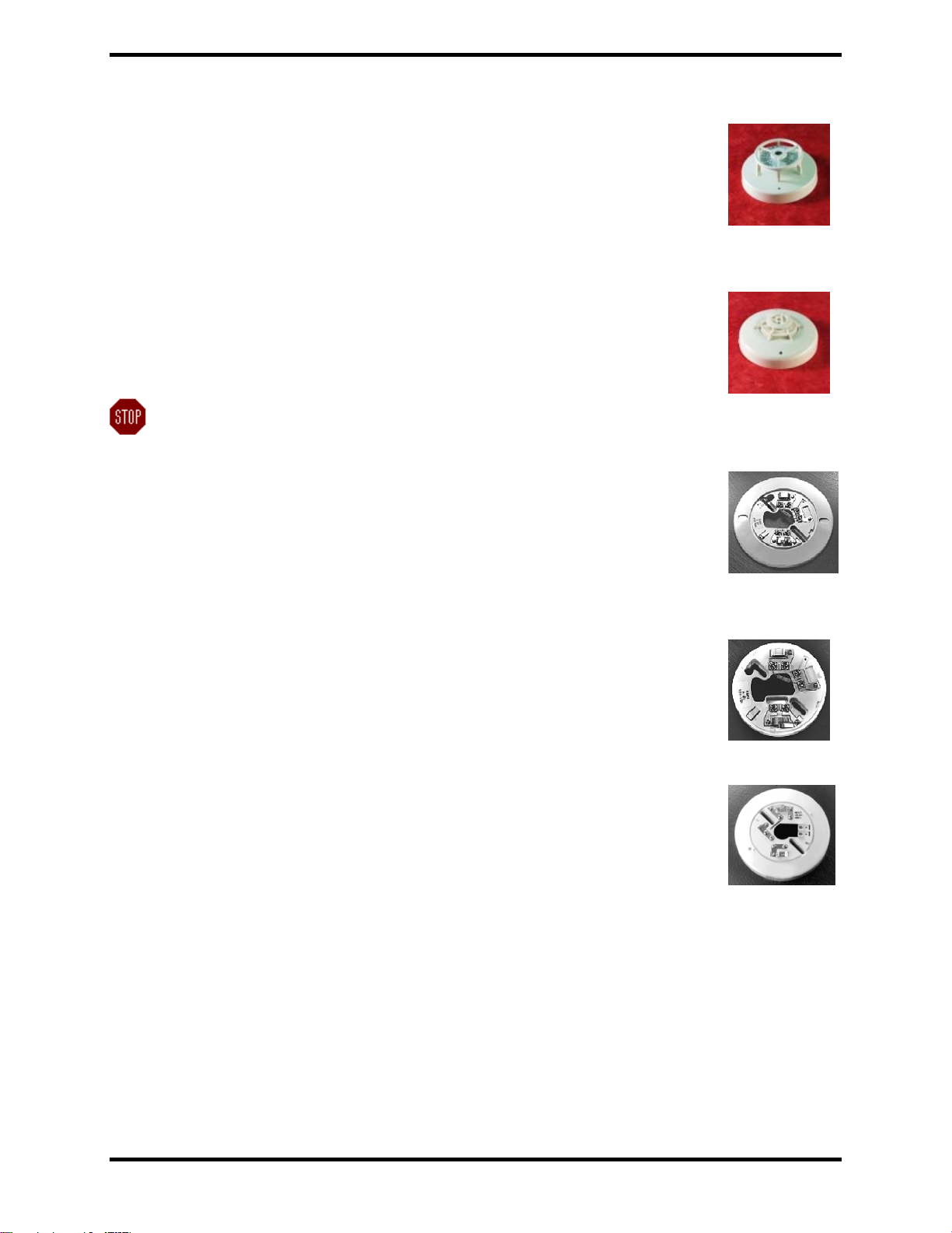
•67-1034 6” Base
Electronics-free 6” base with plastic tamper-lock lug. Contains a 430Ωresistor. Can
be used for Sequential or Cross Zone detection.
•67-1036 4” Base
4” version of the 67-1034
•67-1035 6” Base
Electronics-free base with plastic tamper-lock lug. Contains a 220Ωresistor. Can
be used with Cross Zone or Single Detector Release detection.
•67-1037 4” Base
4” version of the 67-1035
•63-1012 Relay Base
This 6” base is equipped with a 430Ωresistor and two sets of Form “C” relay
contacts.
3.3 OUTPUT DEVICE
Refer to FIKE Notification Appliance and Releasing Compatibility Document (06-186).
firealarmresources.com
FIKE CORPORATION EQUIPMENT
UL S2203 SHP Product Manual Page 13 of 43
FM 0Z8A0.AY Manual P/N: 06-130 Rev. No: 3, 04/02
3.4 ANCILLARY DEVICES
The following table lists several ancillary devices that can be used in conjunction with the SHP panel to
provide increased system flexibility and performance. For detailed wiring instructions for each of these
devices refer to the appropriate product manual.
P/N Manual P/N Description Function
10-2256 06-159 Digital Alarm Communicator Complies with NFPA 72-Supervising Station
Fire Alarm System
10-1832 06-106 ARM-III (Agent Release Module) Provides primary means for Fike’s Clean
Agent suppression systems
10-107 –
10-110
06-019 Conventional Graphic Annunciator Provides graphic point annunciation for
detectors
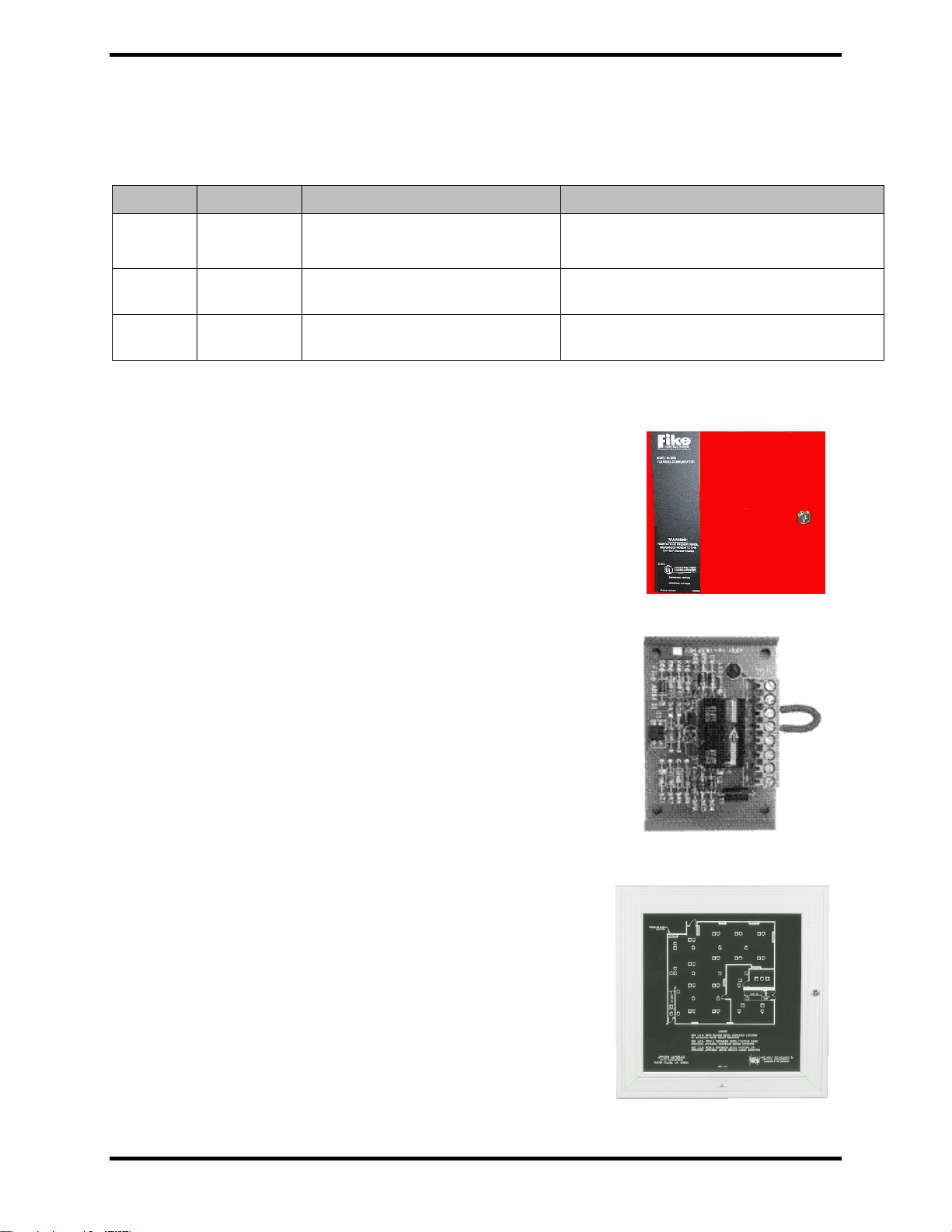
•10-2256 Digital Alarm Communicator/Transmitter (DACT)
The SHP panel is capable of communicating to a Central Station via
the DACT (optional). The DACT monitors the relay outputs of the
SHP. It is necessary to program the DACT with the 10-2257
programmer and 10-2258 cable or 10-2259 modem and 06-151
software.
•10-1832 Agent Release Module (ARM III)
The SHP panel is capable of supporting up to 6 ARM’s on the single
Agent Release Output Circuit. The ARM is required for each Clean
Agent Suppressant Container. Refer to the ARM manual, 06-106 for
detailed instructions on the ARM.
•10-107 – 10-110 Conventional Graphic Annunciator
Fike Graphic Annunciators provide a graphic display of the
protected area using LED’s to indicate the location of smoke
detectors.
firealarmresources.com

EQUIPMENT FIKE CORPORATION
Page 14 of 43 SHP Product Manual UL S2203
Rev. No: 3, 04/02 Manual P/N: 06-130 FM 0Z8A0.AY
3.5 SPARE PARTS
Description Part Number
SHP Enclosure with Transformer 10-2175-c-p
Enclosure Back-box 10-2206-c
Enclosure Door 10-2209-c
Keylock with cam 02-1606
Panel Key Only (without cam) 02-4983
Battery, 7 Amp-Hour 02-2018
Battery, 18 Amp-Hour 02-2820
Battery Cables 10-2192
Standoff and lock washer/hex nut kit (30 each) 02-4035
Transformer, 110VAC 02-3936
Transformer, 208/240 VAC 02-3938
120 VAC Varistor 02-1532
208/240VAC Varistor 02-2275
Mounting hardware for SRM4 or Class A Module
(each uses 4 ea. 3/8” nylon spacer) 02-4008
250V, 12 Amp Fuse (F1) 02-3945
Releasing circuit end-of-line (EOL) assembly, 2.7K 10-2316
Input circuit EOL assembly, 4.3K 10-2318
Output circuit EOL assembly, 2.0K 10-2319
Capacitor, 100uF, 50V (for testing battery circuit) 02-3774
Power terminal (P1) yellow cover 02-4007
Flashbulb (for testing ARM III release) 12/box 02-3799
Touch-Up Paint (Not available from Fike)
Red-Sherwin Williams - #F63VXR9951-4343 Polane
2.8T Plus Polyurethane Enamel
Gray-Sherwin Williams - #F63VXA9975 Polane T
Plus Polyurethane Enamel
firealarmresources.com
Table of contents
Other Fike Security System manuals


