Fleck 3130 User manual

IMPORTANT: Fill in pertinent information on page 2 for future reference.
Model 3130 Downflow
Service Manual

MODEL 3130 Downflow
Job Specification Sheet
Printed in U.S.A.
• JOB NO. __________________________________________________________
• *MODEL NO. ______________________________________________________
• WATER TEST______________________________________________________
• CAPACITY PER UNIT _______________________________________________
• MINERAL TANK SIZE DIA.________HEIGHT_________
• BRINE TANK SIZE &
SALT SETTING PER REGENERATION: _________________________________
Page 2
* CONTROL VALVE SPECIFICATIONS
1) Type of Timer (see pages 18-22)
A) 7 day or 12 day
B) * 1,250 to 21,250 gallon meter or
* 6,250 to 106,250 gallon meter or
* Other ___________________________________________________
C) Meter Wiring Package
1) System #4 - 1 tank; 1 meter; immediate or delayed regeneration
2) System #5 - 2 tanks; 2 meters; interlock
3) System #6 - 2 tanks; 1 meter; series regeneration
4) System #7 - 2 tanks; 1 meter; alternator
2) Timer Program Settings
A) Backwash _________________________________min.
B) Brine & Slow Rinse _________________________min.
C) Rapid Rinse _______________________________min.
D) Brine Tank Refill ____________________________min.
3) Drain Line Flow Controller________________________gpm
4) Brine Line Flow Controller________________________gpm
5) Injector Size # _________________________________
6) A) Hard Water By-Pass
B) No Hard Water By-Pass

Printed in U.S.A.
Page 3
MODEL 3130 Downflow
General Commercial Pre-Installation Check List
WATER PRESSURE: A minimum of 25 pounds of water pressure is required for regeneration valve to operate
effectively.
ELECTRICAL FACILITIES: A continuous 115 volt, 60 Hertz current supply is required. (Other voltages available.)
Make certain the current supply is always hot and cannot be turned off with another switch.
EXISTING PLUMBING: Condition of existing plumbing should be free from lime and iron buildup. Piping that is built up
heavily with lime and/or iron should be replaced. If piping is clogged with iron, a separate iron filter unit should be
installed ahead of the water softener.
LOCATION OF SOFTENER AND DRAIN: The softener should be located close to a drain.
BY-PASS VALVES: Always provide for the installation of isolation and by-pass valves.
CAUTION: Water pressure is not to exceed 120 p.s.i., water temperature is not to exceed 100˚F, and the unit cannot be
subjected to freezing conditions.
INSTALLATION INSTRUCTIONS
1. Place the softener tank where you want to install the unit making sure the unit is level and on a firm base.
(Maximum 7 feet apart for twin units.)
2. All plumbing should be done in accordance with local plumbing codes. The pipe size for the drain line should be the
same size or larger than the drain line flow control connection. Water meters are to be installed on soft water
outlets. Twin units with (1) one meter shall be installed on common soft water outlet of units. If possible, minimize
height of drain line above valve.
3. Make sure that the floor is clean beneath the salt storage tank and that it is level.
4. Place approximately 1″of water above the grid plate (if used) in your salt tank Salt may be placed in the unit at this
time.
5. Close softener isolation valves and open the bypass valve. Turn on the main water supply. Open a cold soft water
tap nearby and let run a few minutes or until the system is free from foreign material (usually solder) that may have
resulted from the installation.
6. Open the softener inlet valves and close the bypass valve.
7. Manually index the softener control into “service” position and let water flow into the mineral tank. When water flow
stops, close inlet valve, place control in “backwash” position to relieve head of air, then gradually open inlet valve to
purge remaining air in tank. Return control to “service” position.
8. Electrical: All electrical connections must be connected according to codes. Use electrical conduit if applicable.
Remote meter systems and twin meter system wiring diagrams are on pages 25-30.
9. Teflon tape is the only sealant to be used on the drain fitting. The drain from twin units may be run through a
common line.
10. Plug into power supply.

Printed in U.S.A.
Page 4
MODEL 3130 Downflow
Water Conditioner Flow Diagrams

Printed in U.S.A.
Page 5
MODEL 3130 Downflow
Water Conditioner Flow Diagrams (Cont’d.)

Printed in U.S.A.
Page 6
MODEL 3130 Downflow
Water Conditioner Flow Diagrams (Cont’d.)

Printed in U.S.A.
Page 7
MODEL 3130 Downflow
Water Conditioner Flow Diagrams (Cont’d.)

Printed in U.S.A.
Page 8
MODEL 3130 Downflow
Water Conditioner Flow Diagrams (Cont’d.)

Printed in U.S.A.
Page 9
MODEL 3130 Downflow
Water Conditioner Flow Diagrams (Cont’d.)
Printed in U.S.A.
Page 10
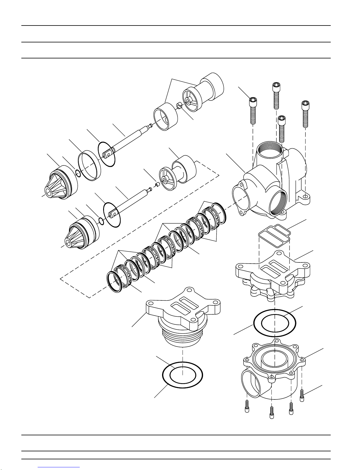
MODEL 3130 Downflow
Control Valve
(See opposite page for parts list)
1
2
3
4
7
8
10
11
12
13
14
15
9
5
6
9
7
6
5
16
17
19
20
21
3
2
2
4
3
10
8
22
22
Table of contents
Other Fleck Control Unit manuals


Popular Control Unit manuals by other brands

Festo
Festo Compact Performance CP-FB6-E Brief description

Elo TouchSystems
Elo TouchSystems DMS-SA19P-EXTME Quick installation guide

JS Automation
JS Automation MPC3034A user manual

JAUDT
JAUDT SW GII 6406 Series Translation of the original operating instructions

Spektrum
Spektrum Air Module System manual

BOC Edwards
BOC Edwards Q Series instruction manual

KHADAS
KHADAS BT Magic quick start

Etherma
Etherma eNEXHO-IL Assembly and operating instructions

PMFoundations
PMFoundations Attenuverter Assembly guide

GEA
GEA VARIVENT Operating instruction

Walther Systemtechnik
Walther Systemtechnik VMS-05 Assembly instructions

Altronix
Altronix LINQ8PD Installation and programming manual


