manuals.online logo
Brands
  1. Home
  2. •
  3. Brands
  4. •
  5. Festo
  6. •
  7. Control Unit
  8. •
  9. Festo VZXF Series Parts list manual

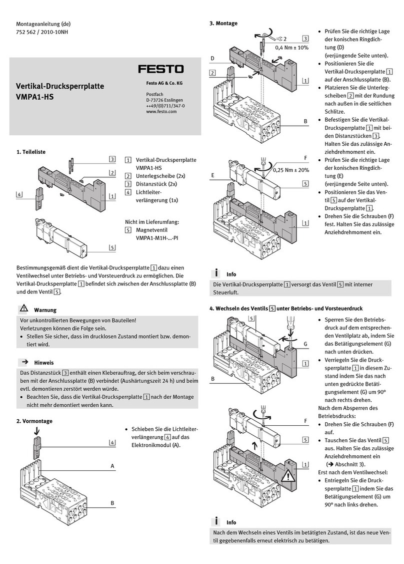
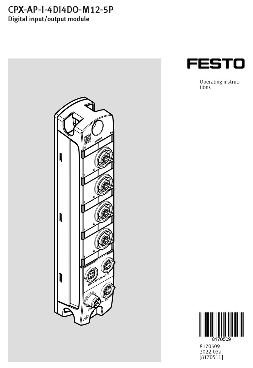
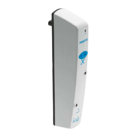
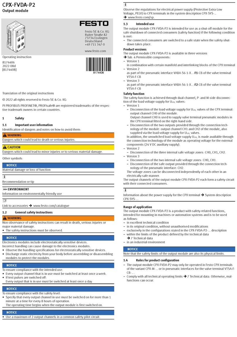
Festo VZXF Series Parts list manual

Translation of the original instructions
1 About this document
This document describes the use of the above-mentioned product.
1.1 Further applicable documents
All available documents for the product èwww.festo.com/pk.
2 Safety
2.1 General safety instructions
– Only use the product in original status without unauthorised modifications.
– Only use the product if it is in perfect technical condition.
– Observe labelling on the product.
– Use the valve only in the flow direction indicated.
– Take into consideration the ambient conditions at the location of use.
Media
– Only use media in accordance with the specifications è 14 Technical data.
– Do not operate the product with chemically unstable gases, abrasive mediaor
solid materials.
– If water is used: up to approx.1000 ppm of chloride content is permitted.
Avoid tensile stresses.
– If aggressive media are used: limit temperature of medium to 65°C.
Return to Festo
Hazardous substances can endanger the health and safety of personnel and
cause damage to the environment. To prevent hazards, the product should only
be returned upon explicit request by Festo.
– Consult your regional Festo contact.
– Complete the declaration of contamination and attach it to the outside of the
packaging.
– Comply with all legal requirements for the handling of hazardous substances
and the transport of dangerous goods.
2.2 Intended use
The VZXF angle seat valve is intended to control gaseous or liquid media in rigid
piping systems.
– To control liquid media, use only the product variant VZXF-L-M22C-M-B-...
(closing against the direction of medium flow).
2.3 Training of qualified personnel
Work on the product should only be conducted by qualified personnel. The quali-
fied personnel must be familiar with installation of process automation systems.
3 Further information
– Accessories èwww.festo.com/catalogue.
– Spare parts èwww.festo.com/spareparts.
4 Service
Contact your regional Festo contact person if you have technical questions
èwww.festo.com.
5 Product overview
5.1 Design
1Position indicator
2Actuator
3Pipe connection with female
thread; feed or forwarding (corres-
ponding to flow direction)
4Arrow for direction of flow
5Operating medium port
Fig. 1 Product design
5.2 Product variants and type code
The following section explains selected product characteristics that are necessary
to understand the instruction manual. Description of the complete type code
èwww.festo.com/catalogue.
Characteristic Value Description
Type VZXF Angle seat valve, externally controlled
Valve type L In-line valve
Valve function M22C 2/2-way valve, normally closed
Reset method M Mechanical spring
A Over valve seat, for gaseous mediaFlow direction
B Under valve seat, for gaseous and liquid media
G12…G2 Thread G½"…G2"Cable connection
N12…N2 Thread NPT½"…NPT2"
Nominal width 120…450 12 mm…45 mm
–z10…+80 °C (standard)Temperature range of
medium M1 z40…+200 °C
H3 Red brassHousing material
V4 Stainless steel
Actuator housing material AL, AN, B1,
B2, V4
Aluminium; nickel-plated aluminium; brass; nickel-
plated brass; stainless steel
Stem seal material –, T, V Standard (NBR), PTFE, FPM
Actuator size 50, 80 50 mm, 80 mm
3…40 0…3 bar, …, 0…40 barMedium pressure
V –0.9…0 bar
PWIS content –, C Standard, PWIS-free
Tab. 1 Description of key features
5.3 Function
The angle seat valve VZXF-L-M22C-M-.... is an externally controlled 2/2-way valve.
At rest, the valve is closed by spring force (normally closed - NC). If the actuator is
pressurised with operating pressure, it raises the control piston and simultan-
eously the valve disc. The valve opens.
The valve seat is slanted around 45° toward the media flow.
The supply of the operating medium is controlled by an external valve that must
be additionally integrated into the supply cable for the actuator.
2
1
12
Fig. 2 Circuit symbol
8092242
VZXF-L-M22C-M
Angle seat valve
8092242
2018-06b
[8092244]
Instructions| Operating
Festo SE & Co. KG
Ruiter Straße 82
73734 Esslingen
Germany
+49 711 347-0
www.festo.com
6 Transport and storage
• For delivery of used products: Comply with all legal requirements for the
handling of hazardous substances and the transport of dangerous goods. For
returns to Festo è 2 Safety.
• Store the product in a cool, dry, UV-protected and corrosion-protected envir-
onment. Ensure that storage times are kept to a minimum.
7 Assembly and installation
Requirements
NOTICE!
Avoid mechanical stresses on the valve. Do not use the actuator as a lever.
– The piping is unpressurized, and no medium flows in it.
– The line ends are mounted.
– Connecting cables and fittings are clean.
– An additional 3/2-way valve is built into the supply cable of the operating
medium.
Recommendation: For gentle operation, install a flow control valve (1.5 mm) in the
supply cable of the operating medium.
Cleaning the valve
• Remove all transport packaging. The material used in the packaging has been
specifically chosen for its recyclability (exception: oil-impregnated paper =
residual waste).
Traces of residual grease may be evident on the product due to the production
process used.
• Clean the valve immediately before installation.
Connect lines
1. Bring the valve into its mounting position.
– Observe the flow direction. The permitted direction of flow is marked by
an arrow on the valve housing è Fig.1, 4.
2. Connect the piping on the valve housing.
– Tightening torque è Tab. 2 Tightening torque pipe connection.
3. Connect the operating medium line.
– Tightening torque: max. 26 Nm
Connection size ["] ½ ¾ 1 1¼1½2
Max. tightening torque pipe
connection
[Nm] 105 200 350 450 540 620
Tab. 2 Tightening torque pipe connection
8 Commissioning
Requirements
– The valve is fully mounted and connected.
Checking operating conditions
1. Check operating conditions and limit values è 14 Technical data.
2. Check connection points for tightness.
3. Check compatibility of the devices in the system for maximum pressure (con-
sider pressure peaks). If necessary, adjust the application parameters.
Commissioning the valve
1. Supply medium.
2. Slowly apply operating pressure to the valve. The operating pressure required
for reliable switching of the valve depends on the medium pressure
è 14.2 Technical data, pneumatic.
ÄThe valve opens.
9 Operation
WARNING!
Risk of injury from touching hot surfaces.
Valve housing and actuator can become hot at high temperature of medium.
Severe burns are possible.
• Do not touch the angle seat valve during operation or immediately afterward.
• Comply with operating conditions.
• Comply with maintenance conditions è 10 Maintenance.
After longer idle times:
• Actuate the valve several times and check for correct function.
10 Maintenance
WARNING!
Risk of injury from touching hot surfaces.
Valve housing and actuator can become hot at high temperature of medium.
Severe burns are possible.
• Allow the angle seat valve to cool off before working on it.
• Check product regularly from the outside for leakage and function.
• Check function of the product regularly.
• Clean product regularly with commercial cleaning agents.
11 Malfunctions
Fault description Cause Remedy
The valve is faulty. Replace the valve.
The flow direction is incorrect Replace the valve.
The valve does not close.
Operating pressure is still
present or is too high
Check operating pressure and
adjust it, if necessary.
The valve is faulty. Replace the valve.
Medium pressure is too high. Adjust medium pressure.
The valve does not open.
Operating pressure is too low. Check operating pressure and
adjust it, if necessary.
Medium leaks from a leakage
hole.
The valve is faulty. Replace the valve.
Tab. 3
12 Disassembly
WARNING!
Risk of injury from combustion and chemical burns.
The media in the piping system and the valve can be hot and under pressure.
Traces of medium can remain in the product and can escape when open or dis-
mantled.
• Allow the valve and piping to cool and depressurize them.
• Wear specified protective equipment.
NOTICE!
The disassembly of the actuator and valve body is not permitted.
1. Depressurise the piping and the connecting cable of the operating medium.
Allow the valve and piping to cool.
2. Empty the piping and valve completely.
– Make sure no one is located in front of the outlet opening.
– Catch discharging media in a suitable container.
3. Disconnect the connecting cable of the operating medium from the valve.
4. Disconnect the piping connections and remove the valve.
13 Disposal
– Dispose of the product in an environmentally friendly manner. In doing so,
take the remaining media into account (use of problematic materials if applic-
able)
– Observe the local regulations for environmentally friendly disposal.
14 Technical data
14.1 Technical data, general
Type VZXF-L-M22C-M
Design Piston actuator with poppet valve
Actuation type Pneumatic
Sealing principle Soft
Mounting position Any
Type of mounting In-line installation
Valve function 2/2-way, closed, monostable
Flow direction Non-reversible
Exhaust function Without flow control option
Reset method Mechanical spring
Type of control Externally controlled
Product weight èwww.festo.com/catalogue
CE marking In accordance with declaration of conformity
èwww.festo.com/sp
Medium
Medium VZXF-...-A Compressed air grade of filtration 200 ìm, inert gases,
vapour1)
Medium VZXF-...-B Compressed air grade of filtration 200 ìm, inert gases,
water, neutral liquid media, petroleum, petroleum
based hydraulic fluid, vapour1)
Medium pressure [bar] –0,9…40, in accordance with information on product
labelling
Viscosity [mm2/s] £ 600
Operating medium
Operating medium Compressed air to ISO8573-1:2010 [7:4:4]
Operating pressure [bar] 6…10 è 14.2 Technical data, pneumatic
Temperature
Temperature of medium
(NBR, FKM)
[°C] –10…+80
Temperature of medium
(PTFE)
[°C] –40…+200
Perm. min./max. temp (TS)
(NBR, FKM)
[°C] –10…+80
Ambient temperature [°C] –10…+60
Type VZXF-L-M22C-M
Note on materials
VZXF-...-H3AL Housing: red brass; actuator: aluminium
VZXF-...-H3B1 Housing: red brass; actuator: brass
VZXF-...-V4AN Housing: stainless steel; actuator: nickel-plated alu-
minium
VZXF-...-V4B2 Housing: stainless steel; actuator: nickel-plated brass
VZXF-...-V4V4 Housing: stainless steel; actuator: stainless steel
Stem seal NBR (standard), PTFE, FKM
Seat seal PTFE (standard)
FKM (vacuum design, PWIS-free)
1) other media on request
Tab. 4 Technical data, general, VZXF
14.2 Technical data, pneumatic
Nominal pressure and flow rate of process valve
Connection size ["] ½ ¾ 1 1¼1½2
Pipe thread in accordance
with DIN ISO 228
G½ G¾ G1 G1¼ G1½ G2
Pipe thread in accordance
with ANSI B 1.20.1
NPT ½ NPT ¾ NPT 1 NPT
1¼
NPT
1½
NPT 2
Pneumatic connection Gx
Connection size DN 15 20 25 32 40 50
Nominal pressure of process
valve PN VZXF-...-H3
[bar] 16
Nominal pressure of process
valve PN VZXF-...-V4
[bar] 40
Flow rate Kv1)
VZXF-...-A-...-H3...-50 [m3/h] 3.5 6.7 10.8 19 23 28
VZXF-...-B-...-H3...-50 [m3/h] 3.7 5.2 9.6 6 16.5 23
VZXF-...-A-...-V4...-50 [m3/h] 3.8 7.5 12 18.5 25 34.5
VZXF-...-B-...-V4...-50 [m3/h] 3.3 6.5 11 10.7 17.5 19.5
VZXF-...-A-...-H3...-80 [m3/h] – – 12 21.5 30.5 40
VZXF-...-B-...-H3...-80 [m3/h] – – 14.5 19 29.5 30
VZXF-...-A-...-V4...-80 [m3/h] – – 12.5 19 29 47.5
VZXF-...-B-...-V4...-80 [m3/h] – – 12 17.5 28 39
1) water, at +20°C, medium pressure 1bar at the valve input, free outlet
Tab. 5 Technical data, pneumatic, VZXF
Operating pressure and medium pressure VZXF-...-A-... (medium flow under
valve seat)
DN20
DN25
DN15
DN32
DN40
DN50
p1 Medium pressure p2 Operating pressure
Fig. 3 Operating pressure and medium pressure VZXF-...-A-...-H3B1-...-50
DN20
DN25
DN15
DN32
DN40
DN50
p1 Medium pressure p2 Operating pressure
Fig. 4 Operating pressure and medium pressure VZXF-...-A-...-V4V4-...-50
DN32
DN40
DN50
p1 Medium pressure p2 Operating pressure
Fig. 5 Operating pressure and medium pressure VZXF-...-A-...-H3AL-...-80
DN32
DN40
DN50 DN25
p1 Medium pressure p2 Operating pressure
Fig. 6 Operating pressure and medium pressure VZXF-...-A-...-V4V4-...-80
Operating pressure and medium pressure VZXF-...-B (medium flow under valve
seat)
VZXF DN15 DN20 DN25 DN32 DN40 DN50
VZXF-...-B-...-H3...-50
Min. operating pressure [bar] 4.9 4.5 5.3 5.5 5.8 5.7
Max. medium pressure [bar] 16 16 10 7 6 3
VZXF-...-B-...-V4...-50
Min. operating pressure [bar] 5.3 5.5 5.5 5.5 5.5 5.5
Max. medium pressure [bar] 40 20 10 7 6 3
VZXF-...-B-...-H3...-80
Min. operating pressure [bar] – – 4.0 4.2 4.3 4.3
Max. medium pressure [bar] – – 16 12 8 5
VZXF-...-B-...-V4...-80
Min. operating pressure [bar] – – 4.1 4.1 4.1 4.1
Max. medium pressure [bar] – – 22 10 8 5
Tab. 6 Operating pressure and medium pressure, VZXF-...-B

This manual suits for next models

1

Other Festo Control Unit manuals

Festo CP-FB8 Parts list manual

Festo

Festo CP-FB8 Parts list manual

Festo MS6-SV-E User manual

Festo

Festo MS6-SV-E User manual

Festo VOFC-LT-M32C Series User manual

Festo

Festo VOFC-LT-M32C Series User manual

Festo MS9-SV-10V24P User manual

Festo

Festo MS9-SV-10V24P User manual

Festo CMGA-E1-CO User manual

Festo

Festo CMGA-E1-CO User manual

Festo CPX-CM-HPP Operating and installation instructions

Festo

Festo CPX-CM-HPP Operating and installation instructions

Festo VYKB User manual

Festo

Festo VYKB User manual

Festo HMP-...-SL Series User manual

Festo

Festo HMP-...-SL Series User manual

Festo CPX-E- AO-U-I Series User manual

Festo

Festo CPX-E- AO-U-I Series User manual

Festo CPVSC1-M1H-D-H-M5C User manual

Festo

Festo CPVSC1-M1H-D-H-M5C User manual

Festo FRM S-B Series User manual

Festo

Festo FRM S-B Series User manual

Festo CPX-...DE Series User manual

Festo

Festo CPX-...DE Series User manual

Festo DSM Series User manual

Festo

Festo DSM Series User manual

Festo MS6-SV Series User manual

Festo

Festo MS6-SV Series User manual

Festo CP-FB11-E Parts list manual

Festo

Festo CP-FB11-E Parts list manual

Festo VZBA-...-63-T-22-...-V4V4T series User manual

Festo

Festo VZBA-...-63-T-22-...-V4V4T series User manual

Festo HSW-x-AP Series User manual

Festo

Festo HSW-x-AP Series User manual

Festo CHB-C-N User manual

Festo

Festo CHB-C-N User manual

Festo VAEM-S6-S-FAS-4-4E User manual

Festo

Festo VAEM-S6-S-FAS-4-4E User manual

Festo CPX-CM-HPP Parts list manual

Festo

Festo CPX-CM-HPP Parts list manual

Festo CPX-E-PN User manual

Festo

Festo CPX-E-PN User manual

Festo VZQA-C-M22C Series Setup guide

Festo

Festo VZQA-C-M22C Series Setup guide

Festo VZBC-x-FF-x-22-x-V4V4T Series User manual

Festo

Festo VZBC-x-FF-x-22-x-V4V4T Series User manual

Festo VMPA2-M1H-...-G1 Series User manual

Festo

Festo VMPA2-M1H-...-G1 Series User manual

Popular Control Unit manuals by other brands

NXP Semiconductors A3M34SL039 manual

NXP Semiconductors

NXP Semiconductors A3M34SL039 manual

MX Atmos Low Pressure Fitting instructions

MX

MX Atmos Low Pressure Fitting instructions

Infineon CCU6 Interrupt 1 manual

Infineon

Infineon CCU6 Interrupt 1 manual

Advanced micro peripherals CAN4000-8S Hardware reference manual

Advanced micro peripherals

Advanced micro peripherals CAN4000-8S Hardware reference manual

2N APS MINI ENTRYCOM User and service manual

2N

2N APS MINI ENTRYCOM User and service manual

Roland TM-6 PRO Reference manual

Roland

Roland TM-6 PRO Reference manual

Buderus MCM10 installation instructions

Buderus

Buderus MCM10 installation instructions

AcSiP AI7687H user manual

AcSiP

AcSiP AI7687H user manual

Tektronix 7B15 instruction manual

Tektronix

Tektronix 7B15 instruction manual

Racal Instruments 7064R-S-1843 instruction manual

Racal Instruments

Racal Instruments 7064R-S-1843 instruction manual

Samson 2406 Mounting and operating instructions

Samson

Samson 2406 Mounting and operating instructions

Siemens SMF6120 installation instructions

Siemens

Siemens SMF6120 installation instructions

Fast-Stat 1000 installation instructions

Fast-Stat

Fast-Stat 1000 installation instructions

Valcom VIP-848A quick start guide

Valcom

Valcom VIP-848A quick start guide

Samson 41-73 Series Mounting and operating instructions

Samson

Samson 41-73 Series Mounting and operating instructions

Ebyte E103-W02 user manual

Ebyte

Ebyte E103-W02 user manual

Telefire LI-3000 Technical manual

Telefire

Telefire LI-3000 Technical manual

Aventics CL03 operating instructions

Aventics

Aventics CL03 operating instructions

manuals.online logo
manuals.online logoBrands
  • About & Mission
  • Contact us
  • Privacy Policy
  • Terms and Conditions

Copyright 2025 Manuals.Online. All Rights Reserved.