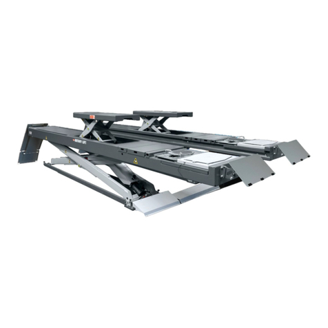
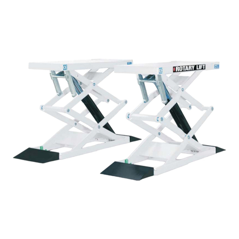
Rotary GEMINI 25-30-35 User manual

PRODUCT SERVICE
GEMINI
25-30-35
SCISSOR LIFT FREE WHEELS
OPERATING INSTRUCTIONS
PONTI SOLLEVATORI A FORBICE
CON RUOTE LIBERE
MANUALE DI ISTRUZIONE
USO E MANUTENZIONE
WorId Leader in Lift Systems

2
WorId Leader in Lift Systems
SCISSOR LIFT
DICHIARAZIONE CE
DI CONFORMITÀ
EC DECLARATION OF
CONFORMITY
La ditta:
ROTARY LIFT EUROPE S.r.l.
Via Tiburtina Km 209+800
65025 - MANOPPELLO SCALO - PESCARA (ITALIA)
Tel. 085/8569058-Fax 085/8569059
Ex ditta:
Marte S.r.l
Via Custoza 15
66013-CHIETI SCALO (ITALIA)
Tel. 0871/574008-Fax 0871/574092
DICHIARA SOTTO LA PROPRIA ESCLUSIVA
RESPONSABILITÀ CHE IL PRODOTTO:
DEFINIZIONE DEL MACCHINARIO: PONTE SOLLEVATORE
A DOPPIA FORBICE CON RUOTE LIBERE
MODELLO: GEMINI 25 - 30 - 35
N.DI MATRICOLA: ..........................................................
AL QUALE QUESTA DICHIARAZIONE SI RIFERISCE È CONFOR-
ME ALLE SEGUENTI DIRETTIVE EUROPEE:
98/37/CE-73/23/CE-E 93/68/CE-89/336/CE
DICHIARA ALTRESÌ CHE SONO STATE ESEGUITE LE SEGUENTI
NORME EUROPEE:
EN 292.1-EN292.2- EN 294-EN 349- EN
1050- PREN 811- EN 60204-1-ETS 300 683- EN 55022B- EN 1493.
Nome e indirizzo dell’organismo notificato:
TÜV CERT - Zertifierungsstelle für maschinen
Dudenstraße 28 -
D-68167 Mannheim
Nr. dell’attestato di certificazione:
70/205/10.000106/95 GEMINI 25 - 30
M6 99 01 29366 006 GEMINI 35
(Luogo e data)
. .
(IL RESPONSABILE DI PRODUZIONE)
ANNO DI COSTRUZIONE:
ALIMENTAZIONE:
220/380 Vac -220 Vac -240 Vac -110 Vac
FREQUENZA DI RETE:
50 Hz - 60 Hz
CENTRO DI ASSISTENZA AUTORIZZATO:
The Company
ROTARY LIFT EUROPE S.r.l.
Via Tiburtina Km 209+800
65025 - MANOPPELLO SCALO - PESCARA (ITALIA)
Tel. 085/8569058-Fax 085/8569059
Ex firm:
Marte S.r.l
Via Custoza 15
66013-CHIETI SCALO (ITALIA)
Tel. 0871/574008-Fax 0871/574092
DECLARES ON ONE’S OWN RESPONSIBILITY THAT THE
EQUIPMENT SPECIFIED BELOW:
TYPE OF EQUIPMENTS:
SCISSOR LIFT FREE WHEELS
MODEL: GEMINI 25 - 30 - 35
PART NUMBER: ...............................................................
TO WHICH THIS DECLARATION IS RELATED, CONFORMS
WITH THE FOLLOWING EUROPEAN DIRECTIVES:
98/37/CE-73/23/CE-E 93/68/CE-89/336/CE
IT ALSO DECLARES THAT THE FOLLOWING EUROPEAN RULES
HAVE BEEN RESPECTED :
EN 292.1-EN292.2- EN 294-EN 349- EN
1050- PREN 811- EN 60204-1-ETS 300 683- EN 55022B- EN 1493.
Name and address of the approval body:
TÜV CERT - Zertifierungsstelle für maschinen
Dudenstraße 28 -
D-68167 Mannheim
Certificate number:
70/205/10.000106/95 GEMINI 25 - 30
M6 99 01 29366 006 GEMINI 35
(Place and date)
. .
(MANAGING DIRECTOR)
YEAR OF MANUFACTURE:
VOLTAGE:
220/380 Vac -220 Vac -240 Vac -110 Vac
Hz:
50 Hz - 60 Hz
AUTHORIZED SERVICE CENTER :

3
CONTENTS
PARTE PRIMA
Cap.1- Introduzione - Imballaggio – Trasporto. . . .pag. 4
Cap.2- Descrizione della macchina. . . . . . . . . . .pag. 7
Cap.3- Sicurezza. . . . . . . . . . . . . . . . . . . . . . . .pag. 11
Cap.4- Installazione. . . . . . . . . . . . . . . . . . . . . .pag. 13
Cap.5- Funzionamento. . . . . . . . . . . . . . . . . . . .pag. 21
Cap.6- Manutenzione. . . . . . . . . . . . . . . . . . . . .pag. 22
Cap.7- Inconvenienti e rimedi. . . . . . . . . . . . . . .pag. 23
Cap.8- Accessori. . . . . . . . . . . . . . . . . . . . . . . .pag. 27
Cap.9- Parti di ricambio. . . . . . . . . . . . . . . . . . .pag. 27
PARTE SECONDA (Ad uso degli installatori)
Libretto Metrologico. . . . . . . . . . . . . . . . . . . . . .pag. 35
SIMBOLOGIA
. . . . . . . . . . . . . .RISCHIO-PERICOLO
. . . . . . . . . . . . . . . . . . . . . . .DIVIETO
. . . . . . . . . . . . . . . . . . . .ATTENZIONE
Prestare particolare attenzione alle frasi precedu-
te dagli ideogrammi.
SOMMARIO
FIRST PART
Chapter 1-Introduction-packing-transport. . . . . . .page 4
Chapter 2-Machine description. . . . . . . . . . . . . .page 7
Chapter 3-Safety. . . . . . . . . . . . . . . . . . . . . . . .page 11
Chapter 4-Installation. . . . . . . . . . . . . . . . . . . . .page 13
Chapter 5-Operation. . . . . . . . . . . . . . . . . . . . .page 21
Chapter 6-Maintenance. . . . . . . . . . . . . . . . . . .page 22
Chapter 7-Troubleshooting. . . . . . . . . . . . . . . . .page 23
Chapter 8-Accessories. . . . . . . . . . . . . . . . . . . .page 27
Chapter 9-Spare parts . . . . . . . . . . . . . . . . . . . .page 27
SECOND PART (For the use of installer)
Maintenance book. . . . . . . . . . . . . . . . . . . . . . .page 35
SYMBOLS
. . . . . . . . . . . . . . .HAZARD-DANGER
. . . . . . . . . . . . . . . . . . . .PROHIBITED
. . . . . . . . . . . . . . . . . . . . .WARNING
Follow the instruction given by the messages pre-
ceded by a safety alert symbol

4
CAP. 1
- INTRODUZIONE
IMBALLAGGIO - TRASPORTO
INTRODUZIONE
Questo manuale è stato scritto per il personale di officina
addetto all’uso del sollevatore (operatori) e per i tecnici
addetti alla manutenzione ordinaria e straordinaria. La lettu-
ra di questo manuale deve essere effettuata prima di qual-
siasi operazione sul sollevatore. Esso contiene informazioni
importanti per:
•La sicurezza delle persone (addette all’uso e alla
manuenzione ordinaria);
• La sicurezza del sollevatore;
• La sicurezza dei veicoli sollevati.
Il manuale è parte integrante del sollevatore e deve essere
conservato in luogo facilmente accessibile, in modo che l’o-
peratore possa consultarlo rapidamente in qualsiasi momen-
to. SI RACCOMANDA UNA ATTENTA LETTURA DEL CAPI-
TOLO “3” RIGUARDANTE LA SICUREZZA.
I ponti sollevatori “GEMINI” sono stati progettati e costruiti
rispettando:
Le DIRETTIVE EUROPEE 98/37/CE-73/23/CEE e
93/68/CEE-89/336/CEE.
Le NORME EUROPEE EN 291.1-EN 292.2- EN 294 - EN
349 - EN 1050 - EN 60204-1 - ETS 30 683 - EN 55022B -
EN 1493.
Tutte le operazioni sul sollevatore ed in particolare quelle di
trasporto, montaggio, installazione, manutenzione, revisio-
ne, spostamento, smantellamento ecc. devono essere esegui-
te da personale esperto e preventivamente autorizzato. Il
costruttore non risponde di alcun danno a persone, veicoli od
oggetti causato da un uso improprio del sollevatore.
Leggere attentamente le avvertenze contenute in questo
manuale prima di operare sul sollevatore.
Effettuare l’allacciamento pneumatico dal sollevatore
alla centralina di comando solo dopo avere messo in opera
gli impianti elettrici ed oleodinamici.
L’uso del sollevatore è destinato esclusivamente al solle-
vamento di autoveicoli fino alla portata indicata. È vietato
ogni uso improprio del sollevatore.
Provvedere al distacco del sollevatore dalla linea di ali-
mentazione prima di ogni intervento di manutenzione sia
ordinaria che straordinaria
L’installazione del sollevatore deve essere effettuata
rispettando le norme indicate.
Il mancato rispetto delle norme contenute nel presente
manuale, solleva il costruttore da ogni responsabilità.
CHAPTER 1
- INTRODUCTION
PACKING - TRANSPORT
INTRODUCTION
This manual was written for shop technicians ( car lift opera-
tors ) and maintenance technicians. Before operating these
car lifts, please read these instructions completely. This
manual gives helpful information about:
• Safety of people;
• Safety of the car lift;
• Safety of lifted car.
This manual is considered to be a permanent part of the lift
and must be kept in an easily accessible place so that the
operator can find it and refer to it any time.A Particularly
careful reading of chapter 3 on safety is recommended.
All versions of “GEMINI” have been designed and built as
required by:
EUROPEAN RECOMMENDATIONS: EEC 98/37/CEE,
73/23/CEE, 93/68/CEE, 89/336/CEE.
EUROPEAN RULES: EN 291/1992, EN 292/1992, EN 294,
EN349, EN1050, EN 60204-1, EN 300683, EN 55022B -
EN 1493.
Only skilled and previously authorized technicians should be
allowed to carry out transport, assembling, setting, mainte-
nance, overhaul, moving, dismantling operations, etc. con-
cerning the lift. The manufacturer is not responsible for pos-
sible damage to people, vehicles and objects in the case that
said operations are carried out by unauthorized personnel or
the lift improperly used.
Read these instruction completely before operating the
lift.
Always start the hydraulic and electric system before the
pneumatic connection from the lift to the control box is car-
ried out.
The lift must be only used for vehicles up to the speci-
fied capacity. Any inproper use of this lift is strictly forbidden
Disconnect the lift from the main electric supply before
any extraordinary maintenance operation.
Lift installation must be carried out as specified by these
instructions.
The manufacturer is not liable for possible damage resul-
ting from failure to follow the instruction supplied with this
car lift.

5
PACKING IMBALLAGGIO
Il sollevatore, nelle versioni standard, viene spedito già mon-
tato. La configurazione dell’imballo è la seguente (rif. fig. 1):
IMBALLO 1
N.2 basi e pedane (P1-P2) chiuse una sull’altra comprensivi
di pallet e spessori in legno, sigillato con pluriball e regge
metalliche.
N.1 centralina di comando sigillata con pluriball e regge
metalliche con spessori in legno.
N.1 scatola in cartone con all’interno kit collegamenti elettri-
ci oleodinamici e tamponi in gomma.
N.1 set coprispazio (se incassato).
A
B
C
A
B
C
PACKING 1
IMBALLO 1
PACKING 2
IMBALLO 2
1) MODELLI A B C kg
GEMINI 25ET 1600 1250 600 730
GEMINI 30ET 1600 1250 600 740
GEMINI 35ET 1600 1310 600 750
2) Imballo rampe 1900 930 750 200
Standard versions of the car lift are pre-assembled and
equipped as follows (picture 1):
PACKING 1
2 x bases and platforms (p1-p2) placed on top of each other
and sealed with pallet.
1 x control box.
1 x cardboard box equipped with electric and hydraulic con-
nections, rubber pads.
1 x set of space-covering (if recessed).
1) MODELS A B C kg
GEMINI 25ET 1600 1250 600 730
GEMINI 30ET 1600 1250 600 740
GEMINI 35ET 1600 1310 600 750
2) Ramp packig 1900 930 750 200
pict. - fig.
1
IMBALLO 2
N.1 set rampe salita/discesa o stazionamento (se a pavi-
mento).
PACKING 2
1x set of lifting/lowering or placing ramps (if on floor)

6
TRASPORTOTRANSPORT
pict. - fig.
2
L’imballo può essere sollevato o spostato sia con carrelli ele-
vatori che con gru o carri ponte. L’eventuale imbracatura
deve essere sempre accompagnata da una persona al fine di
scongiurare pericolose oscillazioni del carico. All’arrivo,
verificare che la merce non abbia subito danni e che ci siano
tutti i pezzi indicati nella lista di spedizione. Comunicare
immediatamente all’incaricato o al trasportatore eventuali
mancanze o irregolarità e eventuali danni che il sollevatore
abbia subito durante il trasporto. Rispettare al momento del
carico/scarico merce i punti i punti di presa dell’imballo
come indicato in figura 2.
ELIMINAZIONE DELL’IMBALLO
L’imballo in legno può essere riciclato come pure il “pluri-
ball”, nel caso di eliminazione dell’imballo complessivo atte-
nersi alle normative vigenti nel paese di installazione del sol-
levatore.
Packing can be lifted or moved by fork lift trucks, cranes or
bridge cranes. In case of slinging, a second persons must
always take care of the load to avoid dangerous oscillations.
At the arrival of goods, check for possible damage due to
transport operations. Also verify that all items specified in the
delivery notes are included. In case of damage or possible
defects in transit the person in charge or the carrier must be
immediately informed. Furthermore, during loading and
unloading operations good must be handled as shown in the
picture 2.
PACKING REMOVAL
Wooden packing can be recycled , in case of packing remo-
val, comply with the applicable rules in the lift installation
country.

GRUPPO STRUTTURA FISSA.
E’ costituita dalla base del sollevatore, costruita in una strut-
tura di lamiera di acciaio sagomato con fori di fissaggio al
suolo.
GRUPPO STRUTTURA MOBILE E DI SOLLEVAMENTO
E’
costituita da bracci di acciaio scatolato, e dalla pedana
formata da una lamiera d’acciaio sagomata con montanti di
rinforzo fissata ai bracci con perni di acciaio nei punti fissi,
e con rulli nei punti mobili. Tutte le articolazioni del sistema
di sollevamento hanno boccole autolubrificanti esenti da
manutenzione.
CENTRALINA DI COMANDO.
E’ formata da un box metallico contenente il serbatoio olio e
il gruppo pompa-motore più la pompa manuale, i gruppi
elettrovalvole e gli attacchi per le alimentazioni elettriche,
pneumatiche e oleodinamiche. I comandi sono alloggiati
sulla consolle, tutti funzionano sotto tensione a 24V e sono
del tipo “uomo presente”. Essi sono i seguenti (rif. fig. 4):
7
CAP. 2
- DESCRIZIONE DELLA MAC-
CHINA Modelli - specifiche tecniche
I ponti sollevatori della serie “GEMINI ” sono a doppia for-
bice e fissi, cioè ancorati al suolo. Possono essere forniti sia
a pavimento che ad incasso. Essi sono stati progettati e
costruiti per il sollevamento e lo stazionamento in quota di
autoveicoli.
I nostri sollevatori sono così composti (rif. fig. 3):
A- BASAMENTO (gruppo struttura fissa).
B- BRACCI - PEDANA (gruppo struttura mobile e di solleva-
mento).
C- CENTRALINA DI COMANDO.
FIXED STRUCTURE UNIT.
This is the car lift base, made of steel sheet with floorfixing
holes.
LIFTING AND TRAVELLING STRUCTURE UNIT.
This is composed of box-type steel sheet booms. The load
carryng platform is made of steel sheet with supporting
uprights anchored to the booms by steel pins at the fixed
points, and by rollers at the movable ones. Lifting system links
are equipped with self-lubricating bushings where servicing
is not required.
CONTROL BOX.
The unit with a metallic box that contains oil tank, pump,
motor, hand pump and electro-valve sets.There are also
power, pneumatic and hydraulic supply connections. Low-
voltage controls (24V) are placed on the power unit. they are
the following (picture 4):
CHAPTER 2
- MACHINE DESCRIP-
TION – Models - Specifications
“GEMINI” models are double scissor and fixed (that is
anchored to the ground) car lifts and can be delivered in both
surface or recessed versions. They have been designed and
built for car, van and caravan lifting and placing operations.
Our car lifts are equipped as folows (picture 3):
A-BASE (Fixed structure)
B-BOOMS, PLATFORM (Lifting and travelling structure).
C-CONTROL BOX
TRAVELLING STRUCTURE
STRUTTURA MOBILE
FIXED STRUCTURE
STRUTTURA FISSA
SERIAL NUMBER / N. DI MATRICOLA
NOTE
AVVERTENZE
pict. - fig.
3

8
1. PULSANTE DI SALITA
2. PULSANTE DI DISCESA
3. PULSANTE DI STAZIONAMENTO
4. PULSANTE ESCLUSIONE
5. LED
6. INTERRUTTORE GENERALE
1-Pulsante di salita; premendolo, si attiva il motore ed i mec-
canismi che attuano la salita del sollevatore.
2-Pulsante di discesa; premendolo, si attiva il motore ed i
meccanismi che attuano la discesa del sollevatore.
3-Pulsante di stazionamento; premendolo, si attivano le
sicurezze meccaniche.
4-Pulsante esclusione; premendo questo pulsante si escludo-
no il finecorsa alto e la fotocellula.
5-Led; indica il funzionamento del sollevatore.
6-Interruttore generale; è possibile lucchettare l’interruttore
per impedirne l’uso durante le fasi di riparazione o manu-
tenzione.
I ponti sollevatori a doppia forbice della serie “GEMINI” sono
adatti a sollevare tutti i tipi di autovetture e furgoni con peso
non superiore a 2500/3000/3500 kg.. Di ingombro ridotto,
sono ad altezza variabile in modo da dare la possibilità all’u-
tilizzatore di operare con tranquillità e sicurezza all’altezza
desiderata. Sono forniti di estensione sulla pedana che per-
mette di sollevare senza difficoltà anche le autovetture con
“passo” più lungo. I nostri ponti sollevatori a doppia forbice
possono soddisfare le esigenze di autoriparatori, gommisti,
carrozzieri ecc. con poco ingombro e grande facilità d’uso.
1. LIFTING PUSH BUTTON
2. LOWERING PUSH BUTTON
3. MECHANICAL SAFETY DEVICE
4. LIMIT SWITCH CUTOUT
5. LED
6. MASTER SWITCH
1- Lifting push button: When pressed, motor and lifting
mechanism are operated.
2- Lowering push button: When pressed, motor and lowe-
ring mechanism are operated.
3- Mechanical safety device: When pressed, mechanical
safety is engaged.
4. Limit switch cutout: When pressed, all limit switch on the
lift and photoelectric cell are desactivated.
5. Led: Indicates that the control board is powered.
6. Master switch: The switch can be padlocked to prevent the
use of the lift during the maintenance.
“GEMINI” double scissor car lifts are able to lift vehicals and
van whose weight is no more than 2500/3000/3500 kg. The
height is adjustable so that it can be easily and safely opera-
ted as needed. All version are equipped with extension
platforms so vehicals with a longer “wheel base” can be lif-
ted. Our range of double scissor lifts can meet any demand
coming from car repairmen, tyre dealers, body repairmen
etc.
5
3
26
1
4
pict. - fig.
4
pict. - fig.
5

9
18001555
4505
P1
P2
500
B
1150
2040
A
970
2050
625
500
355
800625
DIMENSIONI DI INGOMBRO “GEMINI 30EP”
(Con rampe di salita e discesa.)
I ponti sollevatori “GEMINI”, sono stati costruiti per il
sollevamento e lo stazionamento in quota di autoveicoli in
ambiente chiuso (richieste particolari a parte). Ogni altro uso
non è consentito, ed in particolare esso non è idoneo per
operazioni di:
-VERNICIATURA;-MONTACARICHI;-SOLLEVAMENTO DI
PERSONE O PONTEGGIO;-PRESSA PER SCHIACCIARE;-
CRIC PER SOLLEVARE .
18001555
4435
P1
P2
500
B
1180
2040
A
970
2050
625
500
355
800625
DIMENSIONI DI INGOMBRO “GEMINI 30EP”
(Con rampe di salita e stazionamento).
GEMINI 25EP
A = 250 mm
B = 1300 mm
GEMINI 35EP
A = 280 mm
B = 1500 mm
GEMINI 30EP
A = 250 mm
B = 1500 mm
GEMINI 25EP
A = 250 mm
B = 1300 mm
GEMINI 35EP
A = 280 mm
B = 1500 mm
GEMINI 30EP
A = 250 mm
B = 1500 mm
“GEMINI 30EP” OVERALL DIMENSIONS
with lifting and lowering ramps)
WARNING: “GEMINI” car lift has been designed and
built to lift and place car at heights in closed areas (special
applications upon request). Any other use is forbidden, and
particularly, the following operations cannot be performed:
- VARNISHING, - LIFTING OF PEOPLE OR SCAFFOLDING,
- SQUASHING PRESS, - CAR JACK OR WHEEL REPLACE-
MENT.
“GEMINI 30EP” OVERALL DIMENSIONS
(with lifting and placing ramps)
pict. - fig.
6
pict. - fig.
7

10
CARATTERISTICHE
• Comandi a bassa tensione (24V).
• Comando centralina a mezzo di scheda elettromeccanica.
• Sincronismo oleodinamico-volumetrico delle pedane senza
barra di accoppiamento.
• Segnale acustico nella fase terminale della discesa.
• Circuito oleodinamico dotato di sicurezza contro la rottura
o il taglio dei tubi ad alta pressione e l’eccesso del carico.
• Dispositivo di sicurezza meccanica a cremagliera.
• Dispositivo per la discesa manuale in caso di assenza di
corrente.
• Doppio dispositivo di autolivellamento delle pedane.
• Sensori di prossimittà ad induzione.
• Tastiera tipo “touchpad.”
1500
1300
500
500
G30ET G35ET
G25ET
1800
1770
G25ET G30ET
G35ET
250
280
G25ET 305ET
G35ET
DATI TECNICI
GEMINI 25 - 30 - 35
• Funzionamento . . . . . . . .Elettro idraulico.
• Portata . . . . . . . . . . . . . .2500-3000-3500 kg.
• Peso . . . . . . . . . . . . . . . 700-800 kg.
• Tempo di salita . . . . . . . . .45 sec.
• Tempo di discesa . . . . . . .45 sec.
• Motore . . . . . . . . . . . . .Trifase 220/380V 3kw 50Hz.
• Alimentazione pneum. . . .4/8 Bar.
• Rumorosità . . . . . . . . . . .<74 dB.
• Temperatura di funz. . . . . .-10°/+50°
• Pressione di esercizio . . . .180/190 Bar.
CHARACTERISTICS
• Low-voltage controls (24V).
• Power unit with electromechanic card.
• Hydraulic-volumetric synchronism of platform without any
torsion bar
• Acoustic signal at the end of the lowering cycle.
• Safety valve in case of hydraulic failure.
• Mechanical safety ratchet.
• Hand lowering device in case of power failure.
• Auto-levelling platform double device.
• Magnetic induction limit switches.
• “Touchpad” control
pict. - fig.
8
DIMENSIONI DI INGOMBRO “GEMINI ET”
(versione incassata).
TECHNICAL DATA
GEMINI 25 - 30 - 35
• Operation . . . . . . . . . . . .Electro-hydraulic.
• Capacity . . . . . . . . . . . . .2500-3000-3500 kg.
• Weight . . . . . . . . . . . . . .From 700 to 800 kg.
• Lifting time . . . . . . . . . . . .45 sec.
• Lowering time . . . . . . . . .45 sec.
• Motor . . . . . . . . . . . . . .3ph 3kw 220/380V 50Hz.
• Pneumatic feed . . . . . . . . .4/8 Bar.
• Noise level . . . . . . . . . . . <76 dB.
• Working temperature . . . .-10°/+50°.
• Working max pressure . . .180/190 Bars
OVERALL DIMENSIONS “GEMINI ET”
(recessed version).

11
CHAPTER 3 -
SAFETY
CAP. 3 -
SICUREZZA
1. E’ importante che in fase di salita o discesa del
sollevatore, l’operatore agisca soltanto nella zona
di comando a lui riservata come indicato in figu-
ra 9.
2. E’ vietato a chiunque sostare o transitare entro
la zona a rischio mentre il sollevatore è azionato,
e comunque quando il veicolo è già sollevato, è
ammessa la presenza sotto di esso solo all’opera-
tore di officina.
3. L’operatore è obbligato, durante le fasi di sali-
ta/discesa del sollevatore, ad assicurarsi che l’a-
rea a rischio sia deserta.
4. Non utilizzare la macchina senza le protezioni
o con le stesse disattivate o manomesse.
5. Per sollevare un autoveicolo, usare i tamponi di
gomma in dotazione rispettando i corretti punti di
appoggio consigliati dal costruttore dell’autovei-
colo.
6. Dopo aver posizionato l’autovettura sul solle-
vatore spegnere il motore ed innestare il freno di
stazionamento, ricordarsi di disinserire la leva del
cambio posizionandola sul “folle”.
7. Per evitare il rischio di caduta dell’autoveicolo
provvedere al suo corretto posizionamento.
8. E’ vietato salire sul veicolo e/o metterlo in moto
con il sollevatore innalzato.
9. E’ vietato lasciare oggetti sotto il veicolo o spar-
1During lifting or lowering operations, the lift
must be operated only from the operator area as
shown in the diagram (picture 9).
2Stopping or passing within the danger area
when the lift is working or already raised is stric-
tly forbidden. Only the operator is allowed to stay
under the lift.
3The operator must make sure the hazard area is
clear when lifting or lowering the lift
4Never use the lift without protection or when
safety devices are off-line.
5Always use the rubber pads when lifting a vehi-
cle, observing the proper points of support speci-
fied by the vehicle’s manufacturer.
6Switch off the engine and engage the parking
brake after placing the vehicle on the car lift;
Furthermore, disengage the shift lever and move it
to the “neutral position.
7To prevent the vehicle from falling make sure it
is properly placed on the lift.
8 Getting in or on the vehicle and-or starting the
engine when the car lift is raised is strictly forbid-
den.
9 Never leave objects and-or obstructions under
the vehicle or scattered on it during the lowering
phase.
PRECAUZIONI GENERALI
E’ molto importante leggere questo capitolo con attenzione
ed in ogni sua parte poichè contiene informazioni essenziali
sui rischi che operatore e manutentore potrebbero correre in
caso d'uso errato o improprio del sollevatore. Essi sono tenu-
ti al rispetto delle prescrizioni contenute in leggi e norme
antinfortunistiche vigenti nel paese in cui è installato il solle-
vatore.
GENERAL RULES
Read this chapter carefully it contains important information
concerning the safety of the operator. The operator and the
maintenance personnel are required to observe the accident
prevention legislation in force in the country of installation of
the lift.
pict. - fig.
9
DANGER AREA
ZONA DI RISCHIO
OPERATOR AREA
ZONA OPERATORE

12
pagliati in fase di discesa del sollevatore.
10. Tenere pulita la zona vicino al sollevatore
pulendo le macchie d’olio al fine di evitare peri-
colosi scivolamenti.
11. E’ vietato usare getti d’acqua-vapore-vernici-
solventi nelle zone presso il sollevatore e la cen-
tralina di comando.
12. E’ rischiosa un'illuminazione non idonea.
Verificare che tutte le zone siano ben illuminate ed
in maniera uniforme.
13. E’ assolutamente vietata la presenza e “l’ar-
rampicata” sulle pedane di persone sia durante il
sollevamento, sia a veicolo sollevato.
14. E’ vietato ogni uso diverso del sollevatore da
quello per cui è stato progettato, la non osservan-
za di questa norma può causare incidenti anche
gravi a persone e cose.
15. E’ assolutamente vietata la manipolazione dei
dispositivi di sicurezza.
16. E’ assolutamente vietato superare la capacità
max. di sollevamento della macchina. Assicurarsi
in tal senso che le vetture non siano cariche.
17. In caso di comportamento anomalo del solle-
vatore, fermarlo e chiudere il selezionatore on/off
bloccandolo con un lucchetto. Il ripristino del fun-
zionamento deve essere fatto da personale esper-
to. Prima della riparazione e manutenzione del
sollevatore assicurarsi che l’alimentazione elettri-
ca sia disinserita dalla rete principale.
10 Keep the area under/next to the lift clear and
remove possible oil spots to avoid the risk of slip-
ping.
11 Never use water-steam-varnish-solvent jets in
the lift area, and particularly, close to the control
box.
12 Proper lighting is extremely important. Make
sure all areas next to the car lift are well and
uniformly lie, according to that specified by the
applicable laws of the place of installation.
13 Climbing on the platform when lifting the vehi-
cle or when the same has been already raised is
strictly forbidden.
14 Any use of the lift other than what herein spe-
cified can cause serious accidents to the operator
as well as to the people in close proximity.
15 The tampering of safety devices is strictly for-
bidden.
16 Never exceed the maximum lifting capacity.
Make sure the vehicles to be raised are without
loads.
17 In case of anomaly, stop the car lift and block
the on/off selector by using a padlock. Only skil-
led technicians should be allowed to restart the lift.
Be sure the power supply is off before repairing
and servicing the lift. The operator, the lift or the
vehicles raised can be seriously damaged if these
instruction are not followed.
DISPOSITIVI DI SICUREZZA
SICUREZZA ANTICESOIAMENTO. Il sollevatore è fornito di
un dispositivo che, in fase di discesa, lo arresta autonoma-
mente a ca. 30 cm. dal suolo per alcuni secondi, emettendo
contemporaneamente un segnale acustico di avvertimento.
INTERRUTTORE FOTO-ELETTRICO. Trattasi di un dispositivo
che blocca la discesa o la salita del sollevatore se un ostaco-
lo si frappone fra le due pedane creando una situazione di
pericolo, o rilevando un dislivello tra le due pedane di ÷ 50
mm.
VALVOLE DI SICUREZZA BLOCCO AUTOMATICO DISCE-
SA. Il dispositivo di sicurezza è costituito da valvole (paraca-
dute) che bloccano automaticamente i cilindri nel caso in cui
la velocità di discesa aumenti in modo incontrollabile. Sono
alloggiate all’interno dei cilindri e impediscono la caduta del
carico nel caso di scoppio o taglio accidentale delle condot-
te oleodinamiche.
SISTEMA A “UOMO PRESENTE”. Il sollevatore è dotato di
un sistema operativo del tipo “uomo presente”. Le operazio-
ni di salita-discesa (e tutte le altre operazioni) vengono
immediatamente interrotte al rilascio dei pulsanti di coman-
do situati sulla consolle della centralina.
SICUREZZA MECCANICA A CREMAGLIERA. Sistema mec-
canico di sicurezza con agganci a cremagliera.
SAFETY DEVICES
ANTI-SHEARING SAFETY. The lift is provided with a device
that stops it automatically for a few seconds at approximately
30 cm from the floor, when the lift is lowered to point the
device produces a warning acoustical signal.
PHOTOELECTRIC SWITCH (PHOTO CELL). A special device
to stop the lift during lowering or lifting operations whenever
the presence of obstructions between the two platforms could
cause dangerous situations or a difference of 50 mm. exist
between the two platforms.
SAFETY VALVE FOR AUTOMATIC LOWERING CUT OUT.
Parachute valves able to automatically lock a single or dou-
ble-acting cylinder in case a sudden increase in velocity
occurs. The valves are located inside the cilynders and pre-
vent the load from falling down in case of sudden pipe bur-
sting or cutting.
DEAD-MAN CONTROL. The car lift is equipped with a dead-
man control. Lowering and lifting operations are stopped
immediately by releasing push button controls.
RACK-TYPE MECHANICAL SAFETY DEVICE. A mechanical
safety device with rack-type hooks .

13
CHAPTER 4 -
INSTALLATION
CAP. 4 -
INSTALLAZIONE
PRIMA DI PROCEDERE ALL’INSTALLAZIONE DEL SOL-
LEVATORE, TOGLIERE L’IMBALLO E CONTROLLARE LA
MERCE.
L’ INSTALLAZIONE DEL SOLLEVATORE E’ DI COMPE-
TENZA DI TECNICI SPECIALIZZATI, INCARICATI DAL
COSTRUTTORE O DAI RIVENDITORI AUTORIZZATI. LA
MANCATA OSSERVANZA DI QUESTA NORMA PUO’
CAUSARE SERI DANNI ALLE PERSONE E ALLE COSE.
Il sollevatore deve essere installato rispettando le distanze di
sicurezza da muri, colonne, altre macchine, ecc. L’altezza
minima del locale deve essere di almeno 4500 mm. La
distanza minima dai muri, considerando lo spazio per lavo-
rare comodamente, la centralina di comando e le vie di fuga
in caso di emergenza deve essere di almeno 1500 mm. Il sol-
levatore può essere piazzato su qualsiasi tipo di pavimento,
purchè lo stesso sia perfettamente piano e di resistenza ade-
guata (min. 250 kg.x cmq.) (rif. fig. 10)
PROCEDURA DI INSTALLAZIONE.
1) Posizionamento del sollevatore.
2) Verifica disponibilità alimentazioni elettriche e pneuma-
tiche.
3) Connessioni elettriche.
4) Connessioni oleodinamiche.
5) Allacciamento rete elettrica.
6) Fissaggio sollevatore.
7) Primo avviamento.
1) POSIZIONAMENTO DEL SOLLEVATORE.
max
2000
h 4500 min.
min.
800
min.
1500
P1 P2
Posizionare il sollevatore con l’aiuto di un carro ponte o altro
mezzo di sollevamento adeguato nel punto desiderato.
Sollevare (per aprire il sollevatore) con una gru le due peda-
ne seguendo le indicazioni in figura per una altezza di ca.
70 cm. assicurandosi che le sicurezze meccaniche siano
inserite. Per spostare il sollevatore imbracarlo come in figura
10 e posizionarlo a dovere. Procedere all’eliminazione di
piccoli dislivelli del suolo servendosi di spessori metallici.
UNPACK THE GOODS AND CHECK FOR POSSIBLE
DAMAGE BEFORE INSTALLING THE LIFT.
ONLY SKILLED TECHNICIANS, APPOINTED BY THE
MANUFACTURER, OR BY AUTHORIZED DEALERS
SHOULD BE ALLOWED TO INSTALL THE CAR LIFT.
SERIOUS DAMAGE TO PEOPLE OR EQUIPMENT CAN
BE CAUSED IF THIS RULE IS NOT FOLLOWED.
The lift must be installed according to the specified safe
distance from walls, columns, other equipments etc. The room
must be a minimum 4500 mm. in height. The minimum
distance from walls must be 1500 mm. take into considera-
tion the necessary space to work easily. Further space for the
control site and for possible runways in case of emergency is
also necessary. The lift can be placed on any floor, as long as
is it perfectly level and sufficiently strong. (250 kg/sqcm)
(picture 10).
INSTALLATION PROCEDURE
1. Lift location.
2. Power supply and pneumatic feed availability.
3. Electric connections.
4. Hydraulic connections.
5. Electric network connection.
6. Lift fixing.
7. Initial running.
1) LOCATION OF THE LIFT
TO OPEN
PER APRIRE TO MOVE
PER SPOSTARE
70 cm
Place the automotive lift using a crane truck or any other lif-
ting equipment. Raise the two platforms using a crane, place
them at a height of about 70 cm. (to open) and make sure the
mechanical safety devices are on. Move the car lift, sling it as
described in picture 10 and adjust the distance between the
two platforms so that they are exactly parallel. After having
set the location of the lift, it may be necessary to level the unit
with metallic shims under the base.
pict. - fig.
10

14
2) VERIFICA DISPONIBILITA’ ALIMENTAZIONE
ELETTRICA E PNEUMATICA.
Il locale deve essere preventivamente predisposto per l’ali-
mentazione elettrica e pneumatica del sollevatore.
Assicurarsi che gli attacchi per tali alimentazioni siano
disponibili nei pressi della centralina.
3) CONNESSIONI ELETTRICHE.
Collegare i cavi numerati provenienti dal sollevatore, (vedi
fig. 11) ai connettori corrispondenti situati nella scheda elet-
trica all’interno della centralina di comando (rif. fig. 12).
N. indiv.
Codice Descrizione
1 06-0302 Fine corsa alto
2 06-0302 Esclusione fotocellula
3 06-0302 Autolivellamento pedana p2
4 06-6606 Fotocellula NC
5 06-0302 Autolivellamento pedana p1
6 06-6603 Catarifrangente
Pos. N.
Code Description
1 06-0302 Lifting limit switch
2 06-0302 Photoelectric cell cut out
3 06-0302 P2 platform self levelling
4 06-6606 Photoelectric cell nc
5 06-0302 P1 platform self levelling
6 06-6603 Reflector
2) POWER SUPPLY AND PNEUMATIC FEED AVAI-
LABILITY CONTROL
The room must be previously arranged for the power supply
and pneumatic feed of the lift. Make sure that supplies are
not far from the power unit.
3) ELECTRIC CONNECTIONS
Connect the lift cables (see picture 11) to the relative con-
nectors placed within the electric card of the power unit (pic-
ture 12).
36
5
42
1
pict. - fig.
11

15
COLLEGAMENTO ELETTRICO SULLA SCHEDA
7
34
152
(CM)
(EA)
5 2
BLKAK
NERO
CONNETTORE PULSANTIERA
TOUCH PAD
BLLU
BLU
BROWNN
MARRONE
1
(SA)
(24 VAC)
(EO) 34
(EL)
(+) (-)
FUSE
10X38 20 A
FUSE
5X20 1 A
00
24
220
380
A1 CM
M
A2
SCHEMA DI CONNESIONE ELETTRICA
ELECTRIC CARD CONNECTIONS
EO
EL
CM
EA
SA
1
2
3
4
5
Lowering oil electrovalve
Levelling electrovalve
Motor contactor
Air electrovalve
Motor saver
Lifting limit switch proximetry
Photocell exclusion proximetry
P2 platform levelling proximetry
Photocell
P1 platform levelling proximetry
EO
EL
CM
EA
SA
1
2
3
4
5
Elettrovalvola olio discesa
Elettrovalvola livellamento
Contattore motore
Elettrovalvola aria
Salvamotore
Proximetri fine corsa alto
Proximetri esclusione fotocellula
Proximetri per livellamento pedana P2
Fotocellula
Proximetri per livellamento pedana P1
WIRING DIAGRAM
pict. - fig.
12
pict. - fig.
13

16
SCHEDA ELETTRICA
C1
C2 R2
C3
IC1
JP1
24V AC
C1
C1
S1
C20
C17
SIR
JP4
SALVA
MOTOR
JP4JP5
PRE. GPL
7EA
GEMI
JP16
M.GEM
JP4
EA
GLP
JP14
EL
F1
IC4
IC5
S2
DL4
DL1
DLD DLF
JP17
DL1
DLMG
DLG DLEG
D23
D31
K6
K13
K1
K2
K3
K17
K10 K9 K8
K12
K15 (T3)
K14
K7
K11
K4 (T1)
K5 (T2)
K16 (T4)
JP9
FCALTO
1
JP11
FCLIV.P1
5
JP10
FC.EFOT.
2PULSANT
JP13
4
FOT
EO
GEMI
JP12
4
FCLIV.P2
ELECTRIC CARD
TIMER - S2 - SU SCHEDA ELETTRICA
121110987654321
TIMERS ADJUSTMENT - REGOLAZIONE TIMER -S2-
NO
2 SEC
2 1
NO
4 SEC
2 1
NO
5 SEC
2 1
NO
6 SEC
2 1
NO
2 SEC
765
NO
3 SEC
765
NO
4 SEC
765
NO
6 SEC
765
NO
0,5 SEC
4 3
NO
1 SEC
4 3
NO
1,5 SEC
4 3
NO
2 SEC
4 3
NO
"T1" STOP TIME FOR LOWERINGADJUSTMENT - REGOLAZIONE TEMPO DI ARRESTO DISCESA
"T2" P2 PISTON PREELUDING TIME ADJUSTMENT - REGOLAZIONE TEMPO DI PRECARICA PISTONE
"T3" TIMER LIFTING TIMER BEFORE THE ACTION ADJUSTMENT - REGOLAZIONE TEMPO DI SALITA PRIMA DELLA DISCESA
TIMER - S2 - ON THE ELECTRIC CARD
JP1/17
D1/37
DL
S1
IC4
C1/24
IC 1-2-3-5
K1/17
R1/44
SIR
S2
IC5
TR1/5
F1
CONNETTORI
DIODI
LED
PULSANTE RESET TIMER
TIMER MICROCHIP
CONDENSATORI
STABILIZZATORI
RELE
RESISTENZE
CICALINO
REGOLAZIONE TIMER
MICROCHIP TIMER
TRANSISTORS
FUSIBILE 5x20 4A
JP1/17
D1/37
DL
S1
IC4
C1/24
IC 1-2-3-5
K1/17
R1/44
SIR
S2
IC5
TR1/5
F1
CONNECTORS
DIODS
LED
RESET TIMER BUTTON
TIMER MICROCHIP
CAPACITOR
VOLTAGE STABILIZER
RELAIS
RESISTORS
BLEEPER
TIMER REGULATOR
BLEEPER MICROCHIP TIMER
TRANSISTORS
FUSE
pict. - fig.
14
pict. - fig.
15

17
4) CONNESSIONI OLEODINAMICHE
A
B
C
D
E
F
P2
E
P1
F
D
A
AIR ELECTROVALVE
ELETTROVALVOLA ARIA
LEVELLING ELECTROVALVE
ELETTROVALVOLA LIVELLO
LOWERING ELECTROVALVE
ELETTROVALVOLA DISCESA
E
E
E
R2
R1
U1
B
C
A
C B
MANDATA P1
SCARICO
AUTOLIVELLAMENTO - MANDATA P2
SCARICO P1 - MANDATA P2
MANDATA P2
SCARICO P2
A
B
C
D
E
F
P1 DELIVERY
DISCHARGE
LEVELLING-P2 DELIVERY
P1 DISCHARGE-P2 DELIVERY
P2 DELIVERY
P2 DISCHARGE
SCHEMA IMPIANTO OLEODINAMICO
P1 P2
M
1 1
2
3
4
9
10
76
8
5
HYDRAULIC PLAN
1
2
3
4
5
6
7
8
9
10
Valvola paracadute
Elettrovalvola di livellamento (EL)
Elettrovalvola di discesa (EO)
Valvola regolatrice di flusso
Valvola di massima
Pompa 5 litri
Motore trifase 4 HP
Filtro di aspirazione
Pompa a mano
Valvola unidirezionale
4) HYDRAULIC CONNECTIONS
1
2
3
4
5
6
7
8
9
10
Parachute valve
Levelling electro valve (el)
Lowering electro valve (eo)
Flow regulator valve
Full force valve
5l. pump
Three phase motor 4 hp
Suction filter
Hand pump
Unidirectional valve
pict. - fig.
16
pict. - fig.
17

18
SCHEMA DI COLLEGAMENTO PNEUMATICO
6
8
9
4
2
7
1
6
3
4
4
5
PNEUMATIC CONNECTION DIAGRAM
1
2
3
4
5
6
7
8
9
Entrata rete pneumatica
Centralina di comando
Elettrovalvola aria
Tubo aria “rilsan” bianco
Raccordo a “T” rap.
Pistoncino sicurezza meccanica
Pedana P 1
Pedana P 2
Gruppo filtro e regolazione aria
1
2
3
4
5
6
7
8
9
Main supply
Control box
Air electro valve
“Rilsan” white air pipe
Tee-piece union
Pneumatic jack for mechanical Safety release
P 1 platform
P 2 platform
Air filter and lubricator
5) ALLACCIAMENTO RETE ELETTRICA
Attenzione: Le operazioni sottoelencate devono esse-
re eseguite da personale qualificato.
Eseguire l’allacciamento di potenza alla centralina di coman-
do come segue:
• Aprire il coperchio della centralina e allacciare, mediante
i morsetti (37-40 rif. fig. 26), il cavo di alimentazione elettri-
ca al cavo collegato all’interruttore generale, facendo passa-
re il cavo di alimentazione nell’apposito spazio situato nel
retro della centralina. Assicurarsi che la linea di alimenta-
zione elettrica sia adeguatamente protetta da interruttore
magnetotermico con capacità e caratteristiche adeguate e
conforme alle normative vigenti di sicurezza.
• Allacciare i cavi provenienti dal sollevatore alla morsettie-
ra della scheda elettrica secondo le indicazioni date nella
figura 12 riguardante le connessioni elettriche, verificare
quindi che le connessioni siano state eseguite nel modo cor-
retto (rif. fig. 12/13/14).
ATTENZIONE!
Prima di agire all’interno della centralina di coman-
do, per l’allacciamento alla rete elettrica o per la ripara-
zione di un guasto agli apparati elettrici, assicurarsi che
l’alimentazione elettrica principale sia disinserita evitando
così la pericolosa possibilità di folgorazione.
5) ELECTRIC SYSTEM CONNECTION
Warning ! Only skilled personnel should be allowed
to perform the operation shown below.
Connect as follow:
• Open the control box front cover and using the terminals
37-40 (picture 26), connect the electric cable to the general
switch cable (be sure that the cable passes trought the proper
space located behind the control box). Before connecting
the electric system, make sure that the power supply plant to
the lift is equipped with the protection devices required by
current standards in the country where the lift is installed.
Connect the lift cables to the relative cables placed within the
electric card as spescified on page 12, and make sure that
the connections are correct. (Refer to pictures 12,13 and 14).
BE CAREFUL
Before accessing inside the control box, for connec-
tion to the power or for the repair of electric equipments
breakdown, make sure that the main power supply is
disconnected, to avoid the possibility of electrocution.
pict. - fig.
18

19
N.pos.
1-2
3-5
4
2
4
39
36
35
34
14
Denominazione
Finecorsa di
prossimità induttivi
Fotocellula
Interruttore generale
Tastiera
Porta fusibili 3
Fusibili
Contattore
Trasformatore
Scheda elettrica
Costruttore
SIEMENS
SELET
Sprecher Schuh
TASTITALIA
WEBER
WEBER
SIEMENS / GE /
AR / SS
LSP
ROTARY LIFT
Tipo
10..30V DC pnp NC
0’3A-Sn1=2mm.
18-12M/pnp NC24V
-L3-32-1753 16A
D.ROTARY LIFT
32A-690V
Vari
16A - 18A
70VA
D.ROTARY LIFT
Max. utilizzo
N.pos.
3
5
4
6
9
Denominazione
Elettrovalvola aria
Raccordi pneumatici
Tubo pneumatico
Pistoni aria
Gruppo filtro/
regolazione aria
Costruttore
ACL/MM
VARIO
RILSAN
ROTARY LIFT
AIR
SISTEM
Tipo
24V~50/60 HZ 8VA
VARIO
Ø 4x6
FR+L 1/4
Max. utilizzo
10 Bar
16 Bar
30 Bar
15 Bar
-
N.pos.
17
12
25
10
9
5
3
2
9
1
P1
P2
4
Denominazione
Coperchio serbatoio
Serbatoio
Filtro
Pompa
Motore
Valvola max pressione
Elettrovalvola discesa
Elettrovalvola
livellamento
Pompa a mano
Valvola paracadute
Pistone P1
Pistone P2
Tubo Idraulico R1
Tubo idraulico R2
Raccordi idraulici
a pressare
Raccordi idraulici
Valvola controllo
regolatrice di flusso
Costruttore
ROTARY LIFT
ROTARY LIFT
FBN
HYDROIRMA
ELPROM/ELD
TECNORD
TECNORD
TECNORD
TECNORD
MONTI
ROTARY LIFT
ROTARY LIFT
MANULI
MANULI
VARI
VARI
TECNORD
Tipo
-
-
-
AP100/5-D-319
220/380-3PM-50HZ
1400 RPM 3KW 4HP IP54
24AC 50HZ 20W
89.01.952.1.9
Ø110 x Ø 45 x L560
Ø100 x Ø 45 xL 560
VARIO
VARIO
VARIO
VARIO
VRC 10/11
Max. utilizzo
250 Bar
85/220 Bar
250 Bar
250 Bar
300 Bar
300 Bar
210 Bar
400 Bar
400 Bar
400 Bar
230 Bar
PARTICOLARI COMMERCIALI IMPIANTO ELETTRICO (rif. fig. 11-26)
IMPIANTO PNEUMATICO
(rif. fig. 18)
IMPIANTO IDRAULICO
(rif. fig. 17-26)
6) FISSAGGIO SOLLEVATORE
Dopo aver eseguito i collegamenti elettrici ed oleodinamici
(rif. fig. 16/17/28)
, assicurarsi che gli stessi siano effettua-
ti in modo corretto e che le due basi del sollevatore siano
perfettamente parallele. Fissare quindi il sollevatore al
suolo e, usando le basi come dime, forare con una punta
da Ø 16 mm. il pavimento per una profondità di ca. 150
6) LIFT FIXING
After making electric and hydraulic connections (refer to
pictures 16,17,28), make sure they are properly connec-
ted. Now fix the lift to the floor, using the bases as templa-
tes, drill a hole into the floor a 16 mm.Ø bit must be used
up to a depth of about 150 mm., clean the holes, place the
proper inserts with light hammer blows and finally tighten
N.pos.
1-2
3-5
4
2
4
39
36
35
34
14
Denomination
Proximity
Photoelectric cell
General switch
Touchpad
Fuse holder (3)
Fuse
Contactor
Transformer
Electric card
Manufacturer
SIEMENS
SELET
Sprecher Schuh
TASTITALIA
WEBER
WEBER
SIEMENS / GE /
AR / SS
LSP
ROTARY LIFT
Type
10..30V DC pnp NC
0’3A-Sn1=2mm.
18-12M/pnp NC24V
-L3-32-1753 16A
D.ROTARY LIFT
32A-690V
Vari
16A - 18A
70VA
D.ROTARY LIFT
Max Application
N.pos.
3
5
4
6
9
Denomination
Air Electrovalve
Pneumatic connections
Pneumatic pipe
Air piston
Air filter
Manufacturer
ACL/MM
VARIO
RILSAN
ROTARY LIFT
AIR
SISTEM
Type
24V~50/60 HZ 8VA
VARIO
Ø 4x6
FR+L 1/4
Max Application
10 Bar
16 Bar
30 Bar
15 Bar
-
N.pos.
17
12
25
10
9
5
3
2
9
1
P1
P2
4
Denomination
Cover Tank
Tank
Filter
Pump
Motor
Max pressure valve
Lowering electrovalve
Levelling electrovalve
Hand pump
Parachute valve
P1 Piston
P2 Piston
R1 Hydraulic pipe
R2 Hydraulic pipe
Crimp fitting
Hydraulic connection
Flow regulator
Manufacturer
ROTARY LIFT
ROTARY LIFT
FBN
HYDROIRMA
ELPROM/ELD
TECNORD
TECNORD
TECNORD
TECNORD
MONTI
ROTARY LIFT
ROTARY LIFT
MANULI
MANULI
VARI
VARI
TECNORD
Type
-
-
-
UP10K163 MOD.291
220/380-3PM-50HZ
1400 RPM 3KW 4HP IP54
24AC 50HZ 20W
89.01.952.1.9
Ø110 x Ø 45 x L560
Ø100 x Ø 45 xL 560
VARIO
VARIO
VARIO
VARIO
VRC 10/11
Max Application
250 Bar
85/220 Bar
250 Bar
250 Bar
300 Bar
300 Bar
210 Bar
400 Bar
400 Bar
400 Bar
230 Bar
COMMERCIAL PARTS - WIRING PLANT (Refer to pictures 11-26)
PNEUMATIC SYSTEM (Refer to pictures 18)
HYDRAULIC SYSTEM (Refer to pictures 17-26)

20
mm., pulire i fori ed inserire i tasselli adeguati con leggeri
colpi di martello, serrare quindi i bulloni terminando le
operazioni. Nel caso di posizionamento ad incasso del sol-
levatore, verificare attentamente che lo stesso sia perfetta-
mente centrato nelle proprie sedi. (Per aprire il sollevatore
vedere indicazioni al cap. “4” INSTALLAZIONE).
7) PRIMO AVVIAMENTO
Attenzione! Tutte queste operazioni devono essere
eseguite da personale esperto ed autorizzato.
Seguire attentamente le indicazioni al fine di evitare
danni alle persone e al sollevatore.
Assicurarsi che l’area di rischio sia deserta.
Dopo aver posizionato il sollevatore come descritto ed aver
effettuato i collegamenti elettrici ed idraulici (non eseguire
per ora il collegamento pneumatico), si può procedere alle
operazioni necessarie per il funzionamento del sollevatore.
Aprire lo sportello anteriore della centralina di comando e
svitare il tappo del serbatoio olio (pos. 11 fig. 26), con un
imbuto introdurre 13 litri di olio idraulico “ISO 32”. Portare
l’interruttore generale in posizione “1” (pos. 6 fig. 4) e pre-
mere contemporaneamente il pulsante di salita e il pulsan-
te di esclusione (pos. 1-4 fig. 4) fino alla salita completa
della pedana P1. Se il sollevatore non si muove ma il moto-
re, gira regolarmente, assicurarsi che lo stesso abbia il giu-
sto senso di rotazione, nel caso contrario invertire le fasi
sulla linea di alimentazione elettrica. Introdurre altri 5 LT. di
olio nel serbatoio e premere nuovamente i due pulsanti fino
alla salita completa della pedana P2. Eseguire ora il colle-
gamento pneumatico (rif. fig. 18-28). Per far scendere il
sollevatore premere il pulsante di discesa (pos. 2 fig. 4).
Eseguire le operazioni di salita/discesa per quattro/cinque
cicli per eliminare eventuali depositi di aria nei cilindri con-
cludendo le operazioni (spurgo).
the bolts. In case of an inground lift check it is perfectly cen-
tred. (To open the lift see chapter “4” INSTALLATION).
7) FIRST STARTING
Warning! Only skilled and authorized personnel
should be allowed to perform these operations.
Carefully follow all instructions shown below to pre-
vent possible damage to the car lift or risk of injury
to people.
Be sure that the operating area is cleared of people.
After positioning the lift as specified, and performing elec-
tric and hydraulic connections (do not perform pneumatic
connection yet) the lift can be operated by the procedures
shown below: Open the front door of the control box and
unscrew the oil tank cap (pos.11, picture 26), and using a
funnel pour about 13 l. of ISO 32 hydraulic oil or equi-
valent. Move the master switch to “1” position (pos.6, pic-
ture 4) and simultaneously press “lifting” and “limit switch
cut out” push buttons (see picture4, pos. 1-4) keep them
pressed until the P1 is fully lifted . If motor rotates but lifting
operations cannot be performed, check motor for proper
direction of rotation, change the phases if necessary. Add.
5 l. of oil in the tank and press again the two buttons until
the P2 platform is fully lifted . Perform the pneumatic con-
nection now To lower the car lift, press the “lowering” but-
ton.(picture 4, pos.2). Repeat lifting/lowering operations
three or four times to bleed air from the cylinders.
Table of contents
Other Rotary Lifting System manuals

Rotary
Rotary XS35 Troubleshooting guide

Rotary
Rotary SPOA10NB Series User manual

Rotary
Rotary SPM40 Manual

Rotary
Rotary SL235MP User manual

Rotary
Rotary VLXS7 User manual

Rotary
Rotary AR14 User manual

Rotary
Rotary SPO16 User manual

Rotary
Rotary 600 Series Manual

Rotary
Rotary E Series User manual

Rotary
Rotary MCH14 Series User manual

Rotary
Rotary S42N46CAT-I Instruction Manual

Rotary
Rotary SL135 Manual

Rotary
Rotary 2000 Series User manual

Rotary
Rotary MASTER GEAR MGE 2.0 Manual

Rotary
Rotary SPO55E Manual

Rotary
Rotary S38AK-42CAT Manual

Rotary
Rotary SM65-51 User manual

Rotary
Rotary 200 Series User manual

Rotary
Rotary 100 Series User manual

Rotary
Rotary Sprinter SPO15 Manual