Fly Sky FMS-G3 User manual

Quick Start Guide
快速操作指南 FMS-G3
Http://www.flysky-cn.com
Copyright © 2022 FlyskyTechnology co., ltd
Release date: 2022-07-18
FCC ID: 2A2UNG300

Readthesafety messages listedbelow before operation!
• Donot use theproduct at nightor during bad weatherconditions, like rain orthunderstorms.
Itcan cause erraticoperation or lossof control.
• Donot use theproduct when visibilityis limited.
• Donot expose theproduct to rainor snow.Anyexposureto moisture (wateror snow) may
causeerratic operation orloss of control.
• Interferencemay cause lossof control.Toensure the safetyof you andothers, do not
operatein the followingplaces:
Thankyou for purchasingthe products ofFlysky!Tofindout more aboutour products, visit our
websiteat www.flysky-cn.com.If you encounterany problems during using, pleaserefer to the
manualfirst. If theproblem is stillnot resolved, contactyour local dealerdirectly or contactthe
customerservice staff viaFlysky official website.
• Donot use thisproduct when youare tired, uncomfortable,or under theinfluence of alcohol
ordrugs. Doing somay cause seriousinjury to yourselfor others.
• The2.4GHz radio bandis limited toline of sight.Always keep yourmodel in sightas a large
canblock the RFsignal and leadto loss ofcontrol.
• Nevergrip the transmitterantenna during operation.It significantly degradessignal quality
andstrength and maycause loss ofcontrol.
• Donot touch anypartof the modelthat may generateheat during operation,or immediately
afteruse. The engine,motor or speedcontrol, may bevery hot andcan cause seriousburns.
• Misuseof this productmay lead toserious injury ordeath. To ensurethe safety ofyou and
yourequipment, read thismanual and followthe instructions carefully.
• Makesure the productis properly installedin your model.Failure to doso may resultin
seriousinjury.
• Makesure that thereceiver's battery isdisconnected before turningoff the transmitter.
Failureto do somay lead tounintended operation andcause an accident.
• Ensurethat all motorsoperate in thecorrect direction. Ifnot, adjust thedirection first.
• Makesure that themodel stays withinrange in orderto prevent lossof control.
CAUTION!
• RISKOF EXPLOSION IFBATTERY IS REPLACEDBY AN INCORRECTTYPE. DISPOSE OF
USEDBATTERIES ACCORDING TOTHE INSTRUCTIONS.
Precautions
Nearany sites
whereother radio
controlactivity
mayoccur
Nearpeople or
roads Onany pond/lake
whenpassenger
boatsare present
Nearpower lines
orcommunication
broadcasting
antennas

Transmitter Overview
[1]CH1SteeringWheel
[2]CH2ThrottleTrigger
[3]CH3Three-positionSwitch
[4]NeckStrapHook
[5]Handle(4 removablebatteries can be
contained)
[6]LogoSticker
[7]LED
[8]BINDButton
[9] ST-Button(Steeringtrim orD/Rdecrease)
[10] TH-Button(Throttletrim orD/R decrease)
[11]PowerSwitch
[12]REVButton(Sterring/Throttle reverse)
[13]ST+ Button(Steeringtrimor D/Rincrease)
[14]TH+(Throttle trim orD/R increase)

Basic Operations
Power on
Followthe stepsbelow to turn on thetransmitter:
1. Checkto makesure that the batteriesare fullycharged and installed correctly.
2. Switchthe Power Switch toON position, atthe time,the transmitter LED is solid on in
green.
Trims
TheST+andST- buttons arefor increasing/decreasing thetrim value oftheCH1,andTH+and
TH-buttons are forincreasing/decreasing the trimvalue of theCH2.The buzzer willprompt
withtone 1 shortbeep when thetrim is successful.One beeponce for apress. when pressfor a
while,the buzzer willprompt with quickshort beep.Thebuzzer will promptwith 2 shortbeeps
whenthe trim isover the mid-point.When thetrim is atthe end, thebuzzer will prompt with
longbeep.
D/R adjustment
CH1D/R canbe adjustedbyST+/- button.The adjustmentrange is0~120%, the step is 5%,
andthe defaultvalue is 100%.
CH2D/R canbe adjustedbyTH+/-button.The adjustment range is 0~120%, thestep is5%,
andthe defaultvalue is 100%.
Channel reverse
1.Whenthesteering wheel is in thenon-centering state,the channel1 is reversed by
pressingthe REVbutton, and switch once whenthe buttonis pressed.
2.Whenthethrottle trigger is in thenon-centering stateand thesteering wheel is in the
centeringstate, thechannel 2 is reversed by pressing theREV button,and switchonce
whenthe buttonis pressed.
Note: When the channel reverse takes affect by pressing the REV button, the buzzer will
prompt with 1 beep, and the beeps for CH1 andCH2 are different.
Binding
Followthe stepsbelow to bind with thereceiver:
1. Pressand holdthe BIIND button while turningon thetransmitter,the transmitterLED
willflash fast.
2. Putthe receiverinto binding mode by poweringon thereceiver,the receiver LED flash
qucikly.
3. The binding process isfinished whenthe transmitterLED stops flashing and is solidon.
4. Checkto makesure the transmitter and receiverare workingcorrectly, ifthere are any
issuesor unexpectedoperation arise, follow the stepsabove tobind again.
Note: If the transmitter disconnects with the receiver, the transmitter LED will go into three-
flash-one-offstate.

Failsafe
Low voltage alarm
Stick Calibration
Data resetting
Idle alarm and Sleep mode
Whenthe transmitteris turned on, keepthe channeloutput at the desired value,then
pressand holdthe BINDbutton for3S, afterthe buzzerprompts with long beep on tone 1,
thefailsafe isset successful.
Thedefault settingof the failsafe is thelast outputvalue.
Whenthe transmitterrebinds, the failsafe is resetto defaultsetting.
Whenthe transmittervoltage islower than 4.2V,it will enter lowvoltage alarmmode.The
transmitterLED willbe in slow flashing statefor prompt.
Note: When the transmitter voltage is lower than 3.5V, the RF is turned off.
1. Turnthe SteeringWheel tothe Maxendpoint in a clockwise directionand pushthe
triggerforward toits maximum endpoint while poweringon thetransmitter,then the
transmitterenters stickcalibration mode.
2. Turnthe SteeringWheel orpush thetrigger to the Max orMin endpoint,then return
toits neutralpoint.
3. Afterthe calibrationis finished, press the BINDbutton toexit thecalibration mode.
If thecalibration isfailed, then the setting cannot besaved bypressing the BIND
button.
Followthe stepsbelow to reset the data.
1. Pressand holdthe BINDbutton and the REV button while poweringon thetransmitter,
thedata willbe reset.
2. Whenthe operationis successful,the buzzerwill prompt with long beep.
Whenthe transmitteris not operated over 10minutes, itwill gointo idle alarm state.
Inidle alarmstate, the transmitter will exitidle alarmmode whenany control is operated.
Whenthe transmitteris in idle alarm stateover 2minutes,the transmitterwill go into
sleepmode. Insleep mode, the LED isin graduallight state.
Repoweronthe transmitter to exit thesleep mode.
Note: In Sleep mode, the buzzer is off, as well as the RF.The transmitter takes no response
when any control is operating.
Followthe steps belowto calibrate thetransmitter.
Note: When D/R adjustments take affect, the buzzer will promt with a short beep.When it is
atthe end,the buzzer will prompt withlong beep.

Reminder
Whenthe boundreceiver is turned off orthe receiverdisconnects for2S, the transmitter
willin remindermode, and prompt this modeby theLED whichis in flash-three-one-off
state.
Note: When the transmitter has received the information returned by the receiver, it will exit
reminder mode.
Certifications
Specifications
FCC Compliance Statement
This device complies with Part 15 of the FCC Rules. Operation is subject to the following two
conditions: (1) this device may not cause harmful interference, and (2) this device must accept any
interference received, including interference that may cause undesired operation.
Warning: changes or modifications not expressly approved by the party responsible for compliance
could void the user's authority to operate the equipment.
This equipment has been tested and found to comply with the limits for a Class B digital device,
pursuant to Part 15 of the FCC Rules.These limits are designed to provide reasonable protection
against harmful interference in a residential installation. This equipment generates, uses and can
radiate radio frequency energy and, if not installed and used in accordance with the instructions,
may cause harmful interference to radio communications. However, there is no guarantee that
interference will not occur in a particular installation.
ProductName FMS-G3
CompatibleReceiver FMS-R3A
ModelType 1:18,1:24 simulationcars or rock cars
PWMChannels 3
RF 2.4GHzISM
2.4GProtocol AFHDS 2A-BS
Resolution 1024
MaximumPower <20dBm(e.i.r.p.) (EU)
Antenna Singalinternal antenna
InputPower Powered by 4*1.5VAAalkaline batteries
WorkingCurrent 120mA/6V
Distance >100m
OnlineUpdate No
Dimensions 115.2*75.5*145mm
Weight 113g
Certifications CE, FCC ID: 2A2UNG300

FSM-G3
Digital Proportional Radio Control System
本说明书中的图片和插图仅供参考,可能与实际产品外观有所不同。 产品设计和规格可能会有
所更改,恕不另行通知。
Figures and illustrations in this manual are provided for reference only and may differ from actual
product appearance. Product design and specificatiions may be changed without notice.
Manufacturer:ShenZhen FLYSKY Technology Co.,Ltd
Address: 16F, Huafeng Building, No. 6006 Shennan Road, Futian District, Shenzhen,
Guangdong, China
If this equipment does cause harmful interference to radio or television reception, which can be
determined by turning the equipment off and on, the user is encouraged to try to correct the
interference by one or more of the following measures:
-- Reorient or relocate the receiving antenna.
-- Increase the separation between the equipment and receiver.
-- Connect the equipment into an outlet on a circuit different from that to which the receiver is
connected.
-- Consult the dealer or an experienced radio/TV technician for help.
EU DoC Declaration
Hereby, [FlyskyTechnology co., ltd] declares that the Radio Equipment [FMS-G3] is in compliance
with RED 2014/53/EU.
The full text of the EU DoC is available at the following internet address:
www.flysky-cn.com.
RF Exposure Compliance
The device has been evaluated to meet general RF exposure requirement.The device can be used in
portable exposure condition without restriction.
Environmentally friendly disposal
Old electrical appliances must not be disposed of together with the residual waste, but have to be
disposed of separately.The disposal at the communal collecting point via private persons is for
free. The owner of old appliances is responsible to bring the appliances to these collecting points
or to similar collection points. With this little personal effort, you contribute to recycle valuable raw
materials and the treatment of toxic substances.
FCC ID: 2A2UNG300
Table of contents
Other Fly Sky Remote Control manuals
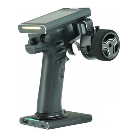
Fly Sky
Fly Sky Noble NB4 User manual
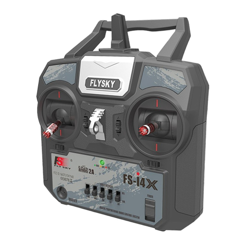
Fly Sky
Fly Sky FS-i4X User manual
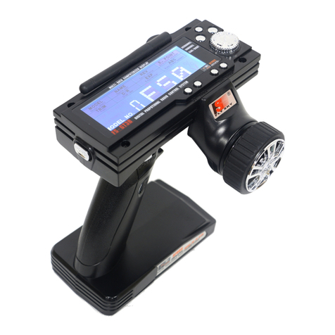
Fly Sky
Fly Sky FS-GT3B User manual
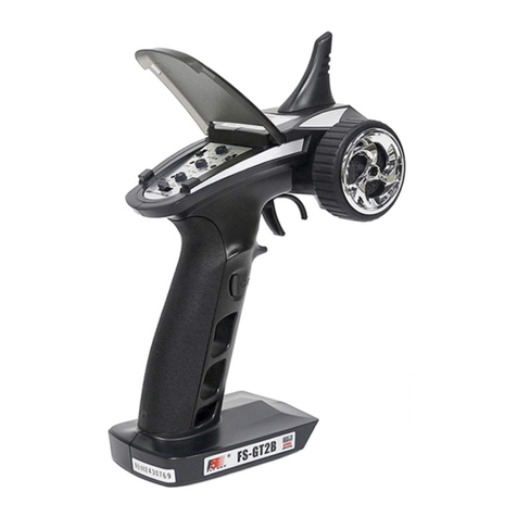
Fly Sky
Fly Sky FS-GT2B User manual
Fly Sky
Fly Sky FS-I4 User manual
Fly Sky
Fly Sky FS-GT3B User manual
Fly Sky
Fly Sky FS-i10 User manual
Fly Sky
Fly Sky FS-VK-G4P User manual
Fly Sky
Fly Sky FS-HW-G4P User manual

Fly Sky
Fly Sky FS-VK-G4P User manual
Fly Sky
Fly Sky FS-GT3 User manual

Fly Sky
Fly Sky FS-GT3 User manual
Fly Sky
Fly Sky FS-T6 User manual
Fly Sky
Fly Sky FS-lT4S User manual
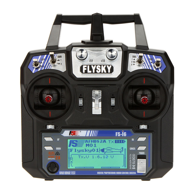
Fly Sky
Fly Sky FS-i6 User manual

Fly Sky
Fly Sky FS-i6 Manual
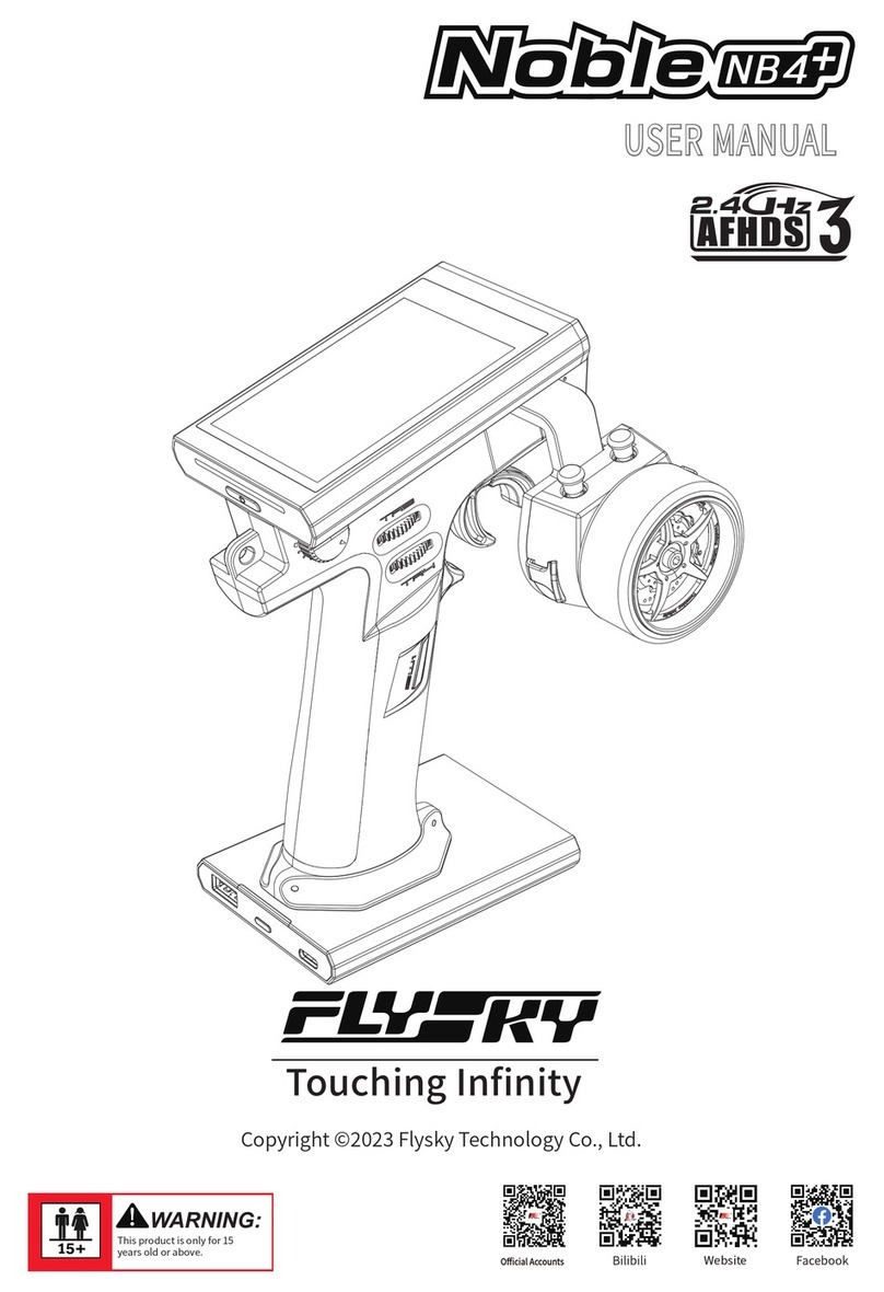
Fly Sky
Fly Sky Noble NB4+ User manual
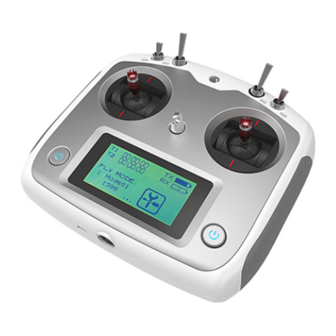
Fly Sky
Fly Sky FS-i6S User manual

Fly Sky
Fly Sky SM001 User manual
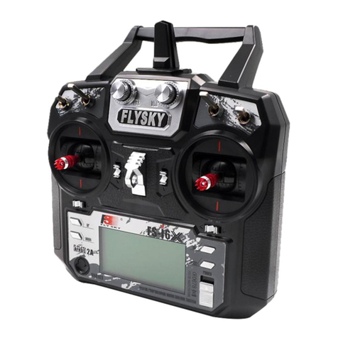
Fly Sky
Fly Sky FS-i6X User manual


