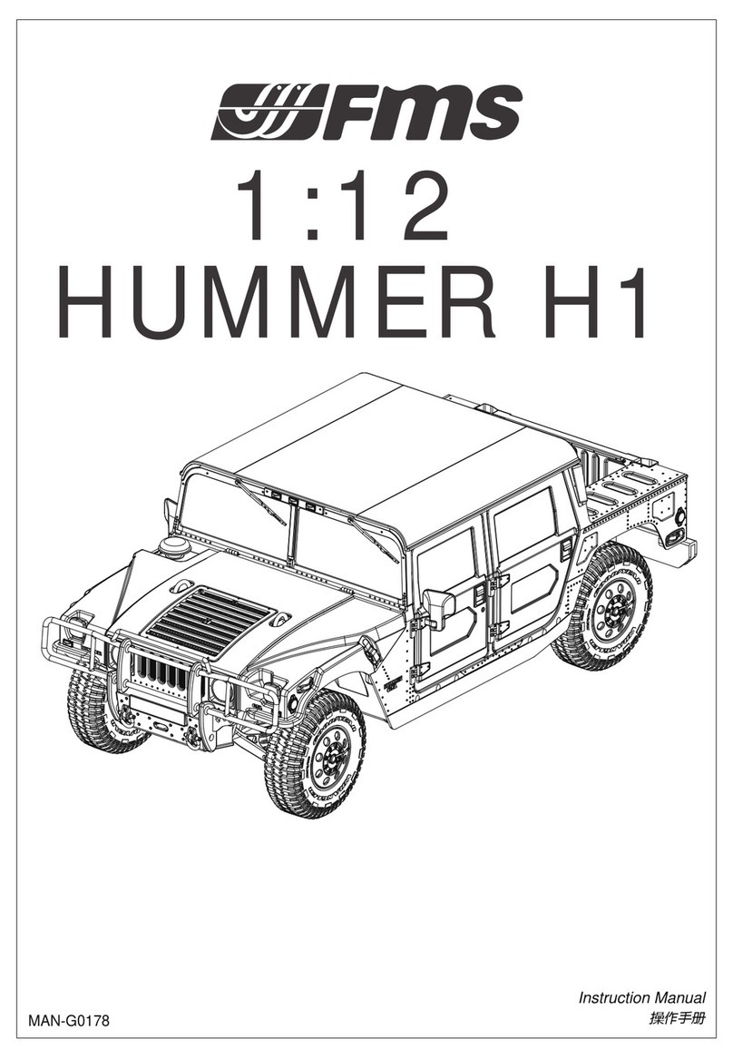
FMS 1/12 Land Rover II Series User manual

Instruction Manual
操作手册
1/12 Land Rover
Series II
MAN-G0168

Introduction
Safety, precautions and warnings
Safety Precautions
1
• Replace damaged components with original factory-parts. Pay special attention to the polarity of all
vehicle wiring.
• Use common sense when selecting the environment to operate your vehicle. Do not operate near
power cables, cellular/radio towers, deep water or unstable terrain. The operator is solely responsible for
their actions.
• The product is composed of precision electrical components. It is critical to keep the product away from
moisture and other contaminants.
• Always check the radio range of the vehicle prior to operation in order to prevent radio loss or
interference.
• Operate this product within your ability. If the vehicle is dangerous to retrieve, it never worth the risk.
• Always turn on the transmitter before connecting the battery on the model. When turning off the model,
always disconnect the battery first, and then turn off the transmitter. If this order is reversed, the model
may become uncontrollable and cause serious damage.
• Never allow transmitter batteries to run low as it may cause loss of vehicle control.
• Plastics on the vehicle are susceptible to damage or deformation due to extreme heat and cold
climate. Do not store the model near any source of heat such as oven or heater. Store the model
indoors, in a climate-controlled, room temperature environment.
Thank you for purchasing our products.
This manual is written to assist you in properly operating, maintaining and repairing the vehicle. As many
of the components used are unique to this product, please retain this manual as a future reference.
Composed of precision-made components, this product is not a toy, thus it is not suited for children under
14 years of age. Minors should be accompanied by an adult when operating. Failure to operate or
maintain this product in a safe manner can result in bodily harm. It is the owner responsibility to operate
this product in a safe manner. FMS and its distributors are not responsible in any way for any and all
bodily harm and/ or property damage that may result from the use of this product.
安全保障措施
指引
感谢您购买我们的产品。
本手册旨在帮助您正确操作、维护和修理车辆。由于本品所涉部件多数为特有部件,请保留本手册作为未来参考
之用。
本产品由精密部件组成,并非玩具,因此不适合 14 岁以下的少年或儿童使用。 未成年人操作时应有成人陪同。
未能以安全的方式操作或维护本产品可能会导致人身伤害。 以安全的方式操作本产品是所有者的责任。 FMS 及
其分销商对使用本产品可能导致的任何和所有人身伤害和/或财产损失概不负责。
安全、预防措施及警告
• 请使用原厂部件更换损坏的部件。特别注意所有车辆接线的正负极。
• 务必选择合适的环境操作遥控模型,所选环境需远离电缆、无线电塔、深水及不稳定地形。 本品操作者对其行
为全权负责。
•本品由精密电子部件构成。请勿将本品暴露于潮湿的环境或者其他污染物中。
•确保每次操作前检查车辆的无线接收范围,以防止无线信号丢失或受干扰。
•在您的能力范围内操作此产品。在任何时候,如果车辆操作有危险,则绝对不值得冒险。
•通电方式:务必先开遥控器再将车子通电。断电方式:务必先将车子断电再关遥控器。以上顺序如逆转,则可
能引起遥控模型失控,导致人身伤害或财产损失。
•遥控器电池低电时,请勿操作模型车,以免出现失控。
•模型产品上的塑胶件容易因极冷或极热气候出现变形或损坏的状况。所以请将模型产品存放在气候受控的室温
环境中,切勿靠近任何热源,如烤箱或加热器等。

CE Warning
FCC Statement
Environmentally friendly disposal
2
This product is not a toy! (14+) Recommended for ages 14 and up. Adult supervision required for ages
under 14 years old. Contains small parts, keep out of reach of children 3 years of age and younger.
The antenna(s) used for this transmitter must be installed to provide a separation distance of at least 20
cm from all persons and must not be co-located or operating in conjunction with any other transmitter.
End-users and installers must be provided with antenna installation instructions and transmitter operating
conditions for satisfying RF exposure compliance.
Old electrical appliances must not be disposed of together with the
residual waste, but have to be disposed of separately. The disposal at the
communal collecting point via private persons is for free. The owner of old
appliances is responsible to bring the appliances to these collecting points
or to similar collection points. With this little personal effort, you contribute
to recycle valuable raw materials and the treatment of toxic substances.
CAUTION
RISK OF EXPLOSION IF BATTERY IS REPLACED BY AN INCORRECT TYPE.
DISPOSE OF USED BATTERIES ACCORDING TO THE INSTRUCTIONS
This equipment has been tested and found to comply with the limits for a Class B digital device pursuant
to part 15 of the FCC rules. These limits are designed to provide reasonable protection against harmful
interference in a residential installation. This equipment generates, uses and can radiate radio frequency
energy and, if not installed and used in accordance with the instructions, may cause harmful interference
to radio communications. However, there is no guarantee that interference will not occur in a particular
installation. If this equipment does cause harmful interference to radio or televison reception, which can
be determined by turning the equipment off and on, the user is encouraged to try to correct the interfer-
ence by one or more of the following measures:
-- Reorient or relocate the receiving antenna.
-- Increase the separation between the equipment and receiver.
-- Connect the equipment into an outlet on a circuit different from that to which the receiver is connected.
-- Consult the dealer or an experienced radio/TV technician for help.
To assure continued compliance, any changes or modifications not expressly approved by the party
responsible for compliance could void the user's authority to operate this equipment.
This equipment complies with Part 15 of the FCC Rules. Operation is subject to the following two
conditions:
(1) This device may not cause harmful interference.
(2) This device must accept any interference received, including interference that may cause undesired
operation.
Caution!
The manufacturer is not responsible for any radio or TV interference caused by unauthorized modifica-
tions to this equipment. Such modifications could void the user authority to operate the equipment.
1. The antenna(s) used for this transmitter must be installed to provide a separation distance of at least
20 cm from all persons and must not be co-lacated or operating in conjunction with any other transmit-
ter.End-users and installers must be provided with antenna installation instructions and transmitter
operating conditions for satisfying RF exposure compliance.
2. Move all your channels to the desired position.
3. Select [All channels] and then [Yes] in the confirmation box.
Safety Precautions 安全保障措施
使用前请仔细阅读本手册。我们不对任何故意损坏或不当使用负责。这个产品不是玩具!建议14岁及以上者使
用。14岁以下的用户,需要在成年人监督下使用。本产品部分包含小零件,请务必保证3岁及以下儿童不能接触
本产品。

IC STATEMENT
3
Safety symbols
Safety guide
Radio System
Not following these instructions may lead to minor injuries.
Not following these instructions may lead to major injuries.
Not following these instructions may lead to serious injuries or death.
Pay close attention to the following symbols and their meanings. Failure to follow these warnings
could cause damage, injury or death.
• Do not use the product at night or in bad weather like rain or thunderstorm. It can cause erratic opera-
tion or loss of control.
• Do not use the product when visibility is limited.
• Do not use the product on rain or snow days. Any exposure to moisture (water or snow)may cause
erratic operation or loss of control.
• Interference may cause loss of control. To ensure the safety of you and others, do not operate in the
following places:
1、Near any site where other radio control activity may occur
2、Near power lines or communication broadcasting antennas
3、Near people or roads
4、On any body of water when passenger boats are present
• Do not use this product when you are tired, uncomfortable, or under the influence of alcohol or drugs.
Doing so may cause serious injury to yourself or others.
• The 2.4GHz radio band is limited to line of sight. Always keep your model in sight as a large object can
block the RF signal and lead to loss of control.
• Do not touch any part of the model that may generate heat during operation, or immediately after use.
The engine, motor or speed control, may be very hot and can ause serious burns.
This device contains licence-exempt transmitter(s)/receiver(s) that comply with Innovation, Science
and Economic Development Canada's licence-exempt RSS(s). Operation is subject to the following two
conditions:
(1) This device may not cause interference.
(2) This device must accept any interference, including interference that may cause undesired operation
of the device.
L’émetteur/récepteur exempt de licence contenu dans le présent appareil est conforme aux CNR
d’Innovation, Sciences et Développement économique Canada applicables aux appareils radio exempts
de licence.
L’exploitation est autorisée aux deux conditions suivantes :
1. L’appareil ne doit pas produire de brouillage;
2. L’appareil doit accepter tout brouillage radioélectrique subi, même si le brouillage est susceptible d’en
compromettre le fonctionnement.
IC: 25584-MG4BS00
IC: 25584-R4A31
无线电系统
安全符号
仔细阅读以下符号及其相关说明,如不按照以下指引进行操作,可能会导致设备损坏或人员伤亡。
Danger
危险
Warning
危险
Caution
危险
如果使用者不按照说明方法操作,有可能导致操作者或他人受到轻微伤害。
如果不按照说明方法操作,可能导致操作者或他人严重受伤,甚至遭受生命危险。
安全信息
Prohibited 禁止

4
Radio System 无线电系统
•请不要在夜晚或雷雨天气使用本产品,恶劣的天气环境有可能导致遥控设备失灵。
•请不要在能见度有限的情况下使用本产品。
•请不要在雨雪或有水的地方使用本产品。如果有液体进入到系统内部,可能会导致运行不稳定或失灵。
•信号干扰可能导致设备失控。为保证您和他人的安全,请不要在以下地点使用本产品:
1、通信基站附近或其他无线电活跃的地方
2、人多的地方或道路附近
3、水域附近
4、高压电线或通信广播天线附近
•当您感到疲倦、不舒服,或在摄入酒精或服食导致麻醉或兴奋的药物后,不要操作本产品。否则可能对自己或
他人造成严重的伤害。
•2.4GHz无线电波段完全不同于之前所使用的低频无线电波段。使用时请确保模型产品在您的视线范围内,大的
障碍物将会阻断无线电频率信号从而导致遥控失灵模型失控。
•请勿在操作过程中或使用后立即触摸模型可能产生热量的任何部分。发动机、电机或速度控制器可能非常热,
并可能导致严重烧伤。
• Misuse of this product may lead to serious injury or death. To ensure the safety of you and your
equipment, read this manual and follow the instructions.
• Make sure the product is properly installed in your model. Failure to do so may result in serious injury.
• Make sure to disconnect the receiver battery before turning off the transmitter. Failure to do so may
lead to unintended operation and cause an accident.
• Ensure that all servos operate in the correct direction. If not, adjust the direction first.
• Make sure the model stays within the systems maximum range to prevent loss of control.
Mandatory 强制
•遥控设备使用不恰当可能导致操作者或他人严重受伤,甚至死亡。为保证您和设备的安全,请仔细阅读使用说
明书并按照要求进行操作。
•使用前必须确保本产品与模型安装正确,否则可能导致模型发生严重损坏。
•关闭时,请务必先关闭接收机电源,然后关闭发射机。如果关闭发射机电源时接收机仍然在工作,将有可能导
致遥控设备失控或者引擎继续工作而引发事故。
•当遥控距离较远时,有发生失控的可能,请适当缩短遥控距离。
•操控时,请先确认模型所有舵机的动作方向与操控方向一致。如果不一致,请调整好正确的方向。

Background 产品背景
5
In 1945, the devastation of World War II had brought about great trauma to Britain, with its economy in
decline and cities destroyed, and many factories bombed. At this time, Rover car company, which had
been known for producing luxury cars before the war, found that luxury cars were no longer in line with
the times, and steel usage was strictly controlled by the government while people's ability to purchase
cars had greatly declined.
To overcome the difficulty, Rover's technical director, Maurice Wilks, led the development of a
versatile four-wheel drive utility vehicle, primarily intended for agricultural use. This vehicle was based
on the American off-road vehicle, and was specifically tailored to meet the demands of farming and
construction work.
In 1948, to differentiate this tool-like off-road vehicle from the traditional Rover brand, a new sub-brand
was created, with the new name "Land " added to the existing "Rover" name, hence the name "Land
Rover". This vehicle became the original Land Rover Series I, and served as the foundation of the
Land Rover brand.
Despite its boxy appearance, the small off-road vehicle sold over 10,000 units in its first year on the
market, thanks to its affordable price and excellent performance, setting the foundation for the later
success of Land Rover in the UK.
Following the success of the Series I, Rover executives saw a bright future and, on the occasion of the
10th anniversary of the Land Rover brand, developed the Series II on the 88- and 109-inch wheelbase
platforms. The Series II not only improved overall workmanship and design, but also introduced
multiple versions for consumers to choose from, including pick-up trucks with long and short wheelbas-
es, and enclosed cargo box utility vehicles. More than 10 versions are available in both hard-top and
canvas soft-top configuration.
Land Rover's inherent spirit of adventure and exploration also won the favor of the British Royal
Family, with Land Rover off-road vehicles becoming a regular fixture in the royal fleet and frequently
used as the transportation of choice for members of the royal family. By the time the Land Rover brand
celebrated its 20th anniversary in 1968, the Series line had sold over 600,000 units, earning
widespread praise in the marketplace.
产品简介
Product Introduction
1945年,第二次世界大战给英国带来了巨大的创伤。经济倒退、城市被毁,很多工厂都遭到了轰炸。罗浮
(Rover)作为当时英国最大的汽车公司,曾经的强项豪华轿车已变得不合时宜。加之钢材用量受到英国政府严
格管控,民众的汽车消费能力大幅下降。
为了渡过难关,罗孚汽车公司的技术总监莫里斯·威尔克斯先生主持开发了一款农用为主的多功能四驱越野
车。这款车以美军吉普为蓝本,更加针对农田和工地这样的使用环境。
1948年,为了区别于传统的罗孚品牌汽车,这辆工具车性质的越野车启用了全新的子品牌——新品牌的名
称在“罗孚(Rover)”的名字前面加上了“Land(陆地、田地)”,定名“Land Rover(路虎)”,而这台
车型就是后来的路虎Series I车型,也是路虎品牌的开山之作。
这台像罐头盒子一样的小越野车,凭借实惠的价格和出色的性能,在上市第一年就卖出了一万台,市场反响
极好,这也为后期路虎汽车在英国的走红奠定了基础。
SeriesⅠ大获成功,让罗孚高层看到了曙光,于是在路虎品牌诞生10周年之际,在88英寸和109英寸轴距平
台上打造了新款车型——Series II。Series II不仅改善了整体工艺,完善了设计,还推出了多个版本供消费者选
择,其中包括长、短轴距的皮卡和封闭货斗的厢式工具车等十多个版本,均提供硬顶和帆布软顶两种配置。
路虎品牌与生俱来的冒险家探索精神也深受英国王室和军队的喜爱,扎实可靠的Series II屡次在阅兵中担任检阅
车。至1968年,路虎品牌成立20周年之际,Series系列车型售出数量已高达60万台,好评如潮。

About Model 产品介绍
The Land Rover brand has gone through several generations of evolution and innovation, and has
never stopped its pursuit of progress. In 2023, FMS has released a highly realistic and fully functional
model of the iconic Land Rover Series II, faithfully reproducing this legendary off-road vehicle.
The Land Rover Series II is extremely accurate in terms of appearance, size and details, with a level of
realism that is comparable to static models. The car shell is designed with scaled rivets, etched grille,
door hinges, a fuel tank cap, engine hood support rod and other features, to increase realism. The
front seats can accommodate three passengers, compatible with 1/12 scale action figures. The front
windshield can be tilted down, and the hood and rear door can open to increase the model's authentic-
ity.
To provide players with more fun and versatility, the Land Rover Series II offers two different styles of
roof, allowing for three different configurations: a hardtop pickup, a hardtop van, and an open-top
vehicle, providing countless possibilities for modifications. The product is equipped with a functional
lighting system, which can be linked with steering direction, adding to the immersive driving experi-
ence. In addition, the Land Rover Series II is built on a durable metal chassis, capable of bearing
various loads, and the suspension system can be adjusted by adding or reducing steel springs to
make it more versatile and durable. The four-wheel drive and two-speed gearbox provide ample
torque and power, delivering a thrilling and exciting driving experience.
Overall, the Land Rover Series II perfectly combines attention to detail with functional control, as well
as the adventurous spirit represented by the brand. This product will become a collectible for Land
Rover fans and off-road enthusiasts, satisfying the users' yearning for off-road adventure and style.
6
产品简介
Product Introduction
路虎品牌至今已历经数代传承与进化,但从未停下进取的脚步,仍然坚持不断地进行技术革新。2023年
FMS推出了一款高度逼真、功能齐全的路虎Series II遥控模型,忠实再现这一传奇车型。
路虎Series II无论在外观、尺寸还是细节上都非常精准,仿真度更加符合原型的风貌,超精细实车细节,堪
比静态车型。车身仿真铆钉设计、精美蚀刻片进气格栅、仿真开门合页、油箱盖、引擎盖撑杆,细节丰富。前
排座椅可容纳三名乘客,可与 1/12 比例的可动人偶兼容;前挡风玻璃可向前放倒,引擎盖、尾门可活动。
为了给玩家提供更多的乐趣,路虎Series II提供了两种不同的车顶样式,可切换硬顶皮卡、硬顶厢式货车、
敞篷车三种形态;全车灯光表达,可方向联动,增加了身临其境的驾驶体验;此外,路虎Series II建立在耐用的
金属底盘上,可承受各种负载,悬架系统可通过增减钢弹簧进行调整。四轮驱动和两档变速可提供充足的扭矩
和动力,带来惊险刺激的操控体验。
总的来说,路虎 Series II 既能满足静态诉求,也能满足动态诉求,它既可以收进精美玻璃罩内做路虎爱好
者的收藏品,也可以驰骋在崎岖道路上满足越野爱好者的操控乐趣。

7
Features
● The whole vehicle adopts ball bearings, making for a more efficient transmission.
● Two-speed transmission, which can be switched freely.
● Four-wheel drive system, excellent off-road performance.
● The structural design of leaf springs and metal beams improves the load-carrying capacity and
durability of the vehicle.
● Fully simulated interior with exquisite details.
● The vehicle lighting system includes direction linkage to enrich user experience.
● The hood, doors on both sides and the tailgate can be opened, and the windshield can be folded
down.
● The roof can be replaced, creating different styles, and providing more personalization options.
特点
产品简介
Product Introduction
● 全车滚珠轴承,传动更高效。
● 两档变速器,可自由切换。
● 四轮驱动系统,具有出色的越野性能。
● 钢板弹簧和金属大梁,提高车身的承载能力和耐久性。
● 全仿真内饰,细节处理精细。
● 全车灯光表达,方向联动,丰富用户体验。
● 引擎盖、两侧车门和尾门可开启,前风挡可放倒。
● 车顶可更换不同样式,提供更加个性化选择。

8
Specification 产品参数
产品简介
Product Introduction
169mm
270mm
31mm
57° 42°
105mm
135mm
149mm
● Length:270mm
● Width:135mm
● Height:149mm
● Wheelbase:169mm
● Tire F/R :Φ 54.8*19.5mm
● Minimum Ground Clearance: 31mm
● Approach Angle: 57°
● Departure Angle: 42 °
● Motor: 180 Brushed motor
● Battery : 2S Lipo 7.4V 380mAh x1
● Remote control distance: 30m
● Approx. operating duration time: 20mins
● Remote control:MG41-BS transmitter,
R4A1 receiver with ESC
group control board
● 车长:270mm
● 车宽: 135mm
● 车高: 149mm
● 轴距: 169mm
● 轮胎: Φ 54.8*19.5mm
● 离地间隙: 31mm
● 接近角: 57°
● 离去角: 42°
● 电机:180有刷电机
● 电池:2S Lipo 7.4V 380mAh
● 遥控距离:30m
● 续航:20mins
● 遥控:MG41-BS发射机,
R4A1接收机/电调(二合一)

The MG41-BS is a simplifed 4-channel transmitter that adopts the 2.4GHz 2A-BS Automatic
Frequency Hopping Digital System. The transmitter is lightweight and compact in design, comfortable
and ergonomic. It has a beginner mode and is easy for beginner players to use.
[1]
[2]
[3]
[4]
[5]
[6]
[7] [13]
[12]
[14]
[16]
[15]
[17]
[18]
[8]
[9]
[11]
[10]
9
MG41-BS 是一款采用 2.4GHz 2A-BS 协议自动跳频数字系统的简版 4 通道双向发射机,外观设计轻便
小巧,手感舒适,符合人体工程学,可通过发射机设置电调参数。该款发射机还具备初学者模式方便入
门玩家使用。
Transmitter Instruction 发射机概览
Transmitter instruction 发射机介绍
[1] Steering Wheel, 35 degrees on each side(CH1)
方向手轮,左右各 35 度(CH1)
[9] RX.BATT, ESC Battery Power Indicator
电调电池电量显示指示灯(RX.BATT)
[10] ST.D/R, to adjust the D/R for steering channel.
方向通道舵量调节旋钮(ST.D/R)
[11] TH.D/R, to adjust the D/R for throttle channel
油门通道舵量调节旋钮(TH.D/R)
[12] Toggle Switch, to set the related function of ESC.
拨码开关(切换电调的工作模式)
[13] TH.REV, Throttle Channel Reverse Button
油门通道反向开关(TH.REV)
[14] G.LED, Status Indicator
状态指示灯绿色 LED(G.LED)
[15] BIND Button
对码按键(BIND)
[16] ST.TRIM, to adjust the trim of steering channel.
方向通道微调旋钮(ST.TRIM)
[17] TH.TRIM, to adjust the trim of throttle channel.
油门通道微调旋钮(TH.TRIM)
[18] POWER ON/OFF, Power Switch
电源开关(POWER OFF/ON)
[4] Three-position toggle switch (CH3)
三档拨动开关(CH3)
[5] Lanyard hole
挂绳孔
[6] Handle, 4*AAA battery compartment
手柄,4*AAA电池仓
[7] ST.REV(Steering wheel reverse)
方方向通道反向开关(ST.REV)
[8] R.LED(Power indicator)
电源指示灯红色 LED(R.LED)
[2] Throttle Trigger, 25 degrees forward and 12.5
degrees backward (CH2)
油门扳机,前 25 度后 12.5 度(CH2)
[3] Push button switch (CH4) [Push button
function is flip type]
按键开关(CH4)[ 按键功能为翻转式 ]

10
Overview
[1] CH1
[2] CH3
[3] CH4
[4] Headlight Interface
[5] Right Turn Signal Light Interface
[6] Fog Light Interface
[7] Fog Light Interface
[8] Left Turn Signal Light Interface
Overview Instruction 接收机概览
接收机
Receiver LED 接收机指示灯
[1] CH1
[2] CH3
[3] CH4
[4] 前灯接口
[5] 右转灯接口
[6] 雾灯接口
* Note: CH1, CH3 and CH4 interfaces use standard 1.25mm*3Pin terminal blocks. The car light interface
uses standard 1.25mm terminal blocks. The battery interface uses an Molex 51005 female connector.
The motor interface is a PH2.0 female terminal blocks.
The LED status indicates the power supply state of the receiver and its working state.
Off: The receiver is not powered on.
Solid on in red: The receiver is connected to the power supply. It works normally.
Fast flashing: The receiver is in the bind mode.
Slow flashing: The LED flashes slowly when the transmitter is powered off, unbound, or no signal.
* 注:CH1 通道、CH3 通道和 CH4 通道接口采用标准的 1.25mm*3Pin 端子座;车灯接口采用标准的
1.25mm 端子座;电池接入采用 Molex 51005 母座接口;马达接口采用 PH2.0 母座端子座。
接收机状态指示灯用于指示接收机的电源及工作状态。
灭:接收机电源未接通。 红灯常亮:接收机已连接电源,并正常工作。
快速闪烁:接收机处于对码状态中。 慢速闪烁:发射机未开机或未对码,无信号情况。
[9] LED
[10] Headlight interface
[11] Antenna
[12] Power Switch
[13] Battery Line Anode
[14] Battery Line Ccathode
[15] Motor Interface "M+"
[16] Motor Interface "M-"
[17] Left Turn Signal Light Interface
[18] Right Turn Signal Light Interface
[19] Tail Light Interface
[20] Brake Light Interface
[21] Backup Light Interface
[22] Signal Pin
[23] + (CH Interface/Light Interface Anode)
[24] - (CH Interface/Light Interface Cathode)
[7] 雾灯接口
[8] 左转灯接口
[9] LED 指示灯
[10] 前灯接口
[11] 天线
[12] 电源开关
[13] 电池线正极
[14] 电池线负极
[15] 马达接口 "M+"
[16] 马达接口 "M-"
[17] 左转灯接口
[18] 右转灯接口
[19] 尾灯接口
[20] 刹车灯接口
[21] 倒车灯接口
[22] 通道信号端
[23] 电源正极
[24] 电源负极

11
Transmitter Battery Installation
Before operation, install the battery and connect the system as instructed below.
Getting Started 使用前准备
开始操作前,请按照本章的顺序和指引安装电池、连接设备。
发射机电池安装
Danger Only use specified battery (X4 AAA batteries).
危险 仅使用厂家指定的电池。
请勿打开、拆卸或自行维修电池。
Danger Do not open, disassemble, or attempt to repair the battery.
危险
请勿挤压、刺穿或接触电池的金属端子。
Danger Do not crush/puncture the battery, or short the external contacts.
危险
请勿将电池置于高温环境或液体中。
Danger Do not expose to excessive heat or liquids.
危险
Danger Do not drop the battery or expose to strong shocks or vibrations.
危险 请注意防止电池跌落、碰撞或振动。
Danger Always store the battery in a cool, dry place.
危险 请将电池存放在干燥阴凉的环境中。
Danger Do not use the battery if damaged.
危险 如果电池损坏,请立即停止使用。
Battery Type: AAA
Follow the steps below to install the batteries:
1. Open the battery compartment cover.
2. Insert 4 AAA batteries with the correct polarity. Make sure it is connect-
ed with the correct polarity to avoid damage.
3. Replace battery compartment cover.
Low battery alarm: When the battery is lower than 4.2V, the transmitter
will give a alarm with the LED flashing slowly.
*Note: When installing the batteries, be careful to handle the positive and
negative poles. (As shown in the picture on the right)
电池类型使用:AAA 电池
请按照以下步骤安装发射机电池:
1. 打开电池仓盖。
2. 将 4 颗电量充足的 AAA 电池装入电池仓内,注意正负极方向并确保电
池上的金属端子与电池仓内的金属端子接触。
3.盖好电池仓盖。
低电量报警:当电量低于 4.2V 时,发射机即发出声音报警同时 LED 慢闪
*注:安装电池时,请留意电池正负极,避免安装错误。( 如右图所示 )
[17] Left Turn Signal Light Interface
[18] Right Turn Signal Light Interface
[19] Tail Light Interface
[20] Brake Light Interface
[21] Backup Light Interface
[22] Signal Pin
[23] + (CH Interface/Light Interface Anode)
[24] - (CH Interface/Light Interface Cathode)

12
Getting Started 使用前准备
Receiver and Servo Installation 接收机与舵机安装
Follow the steps below to turn on the transmitter:
1. Check to make sure that that battery is fully charged and installed correctly.
2. Toggle the switch to the [ON] position. When active the R.LED will be lit.
3. Connect the receiver to power.
• For safety always power on the transmitter before the receiver.
Make sure that the receiver is mounted in an appropriate location within the model, to ensure a stable
signal, maximum range and to mitigate external interference, follow these guidelines:
Pay attention to the following when installing the receiver:
1. "Make sure the receiver is not installed near motors or sources of electrical noise.
2. Keep the receivers antenna away from conductive materials such as carbon or metal. To ensure
normal function, make sure there is a gap of at least 1cm between the antenna and the conductive
material.
After setting up, follow the instructions below to operate the system.
Instructions 操作指引
Power On 开机
请按照以下步骤进行开机:
1. 检查系统状态,确保电池电量充足且安装正确。
2. 将电源开关拨到 [ON] 位置,R.LED 灯常亮。
3. 连接接收机电源。
• 为保障模型及人员安全,使用时请先打开发射机再给接收机上电
请请结合相应模型的结构选择合适的位置安装接收机, 同时为了确保接收机的性能和遥控距离的稳定,并
防止外界干扰,请注意以下操作事项:
1.确保接收机安装在远离电机,电子噪声过多的区域。
2. 接收机天线需远离导电材料 , 例如金属棒和碳纤物质。为了避免影响正常工作,请确保接收机和导电材料
之间至少有 1 厘米以上的距离。
准备操作完成后,您可以按照本章指引开始使用本产品。
Note Operate with caution in order to avoid damage or injury.
警告 此时系统已启动,请谨慎操作,否则可能导致产品损坏或人员伤亡。
Caution To prevent damage do not power on the receiver during installation.
小心 准备过程中,请勿连接接收机电源,避免造成不必要的损失。
Note Make sure that the throttle trigger is at its neutral position and the switches are set to their
proper position.
警告 为了您的安全请将发射机开关和油门打到安全位置。

13
The transmitter and receiver have already been bound at the factory.
However if the receiver needs to be replaced or additional receivers bound follow these steps:
1. Turn on the transmitter while holding the bind button to enter bind mode. G.LED will start flashing
quickly.
• Once in bind mode release the bind button.
2. The receiver will power on and wait for 1 second ,if without connection, it will enter the matching code
automatically;
3. Once the binding is successful, the receiver LED and the G.LED of the transmitter will be solid on.
*Note: When binding, put the transmitter into bind mode first, then the receiver. If the binding is not
completed within ten seconds, the LED of the receiver will enter its slow flashing state.
Binding 对码
发射机和接收机在出厂前已对码成功。
如需更换其他的发射机或接收机,请按照如下步骤进行对码:
1. 将发射机按住对码按键(BIND)开机即进入对码状态,此时 G.LED 快闪,松开对码按键;
2. 接收机上电等待 1 秒没有连接即自动进入对码状态;
3. 对码成功后 , 接收机及发射机指示灯常亮;
*注:对码时请先将发射机进入对码状态,再将接收机进入对码状态 ; 若 10 秒内对码没有完成,接收机 LED
指示灯进入慢闪状态。
1. R.LED: The red power indicator;
2. G.LED: The green status indicator;
3. RX.BATT: ESC battery power indicator.
• When the power is high, the RX.BATT LED will be solid on in green.
• When the power is medium, the RX.BATT LED will be solid on in orange.
• When the power is low, RX.BATT LED will be solid on in red.
• When the power is ultra low, the RX.BATT LED will be flash slow in red.
• When the receiver is not connected, "the RX.BATT LED will maintain the last indicated state.
Instructions 操作指引
LED Indicator LED 指示
1. R.LED: 红色电源指示灯;
2. G.LED: 绿色状态指示灯;
3. RX.BATT: 电调电池电量指示灯
• 电量高:指示灯绿色常亮
• 电量中:指示灯橙色常亮
• 电量低:指示灯红色常亮
• 电量过低:指示灯红色慢闪
• 接收机掉码:指示灯保持最后的指示状态

14
Follow the steps below to turn off the system:
1. Disconnect the receiver power.
2. Toggle the transmitter's power switch to the off position.
This function is used to set the neutral position for throttle and wheel.
Every transmitter is calibrated before leaving the factory, however if recalibration is required,please
follow these steps:
1. Turn and hold the wheel as far clockwise as it will turn, hold the throttle all the way forward, then turn
on the transmitter in calibration mode.
• The R.LED and G.LED will flash twice. • The RX.BATT LED will be solid on in yellow.
2. Calibrate steering wheel: Turn the steering wheel to max and min travel point in clockwise and
counterclockwise.
• The R.LED will be off. • The RX.BATT LED will be solid on in red.
3. Throttle trigger calibration: Push/pull the throttle trigger to forward/backward as far as it will go.
• When the calibration is completed, the G.LED will be off.
• The RX.BATT LED will be solid on in green.
4.Both steering wheel and throttle trigger have finished the calibration.
• The RX.BATT LED will be off.
5. Once the calibration is finished, press the BIND button to save and exit.
Power Off 关机
Stick Calibration 摇杆校准
请按照以下步骤进行关机:
1. 断开接收机电源 ;
2. 将电源开关拨到 [OFF] 位置,使发射机关闭。
该功能可以用于方向手轮和油门扳机的中位角度修正。
发射机在出厂前已校准完成,如需要重新校准,请按照以下步骤执行。
1. 同步将手轮顺时针打到最大、扳机往前推到底并开机,进入校准模式功能;
• R.LED 指示灯和 G.LED 指示灯二闪一灭 • RX.BATT 指示灯黄色常亮
2. 方向手轮校准:将手轮顺时针和逆时针转到最大最小;
• R.LED 指示灯灭 • RX.BATT 指示灯红色常亮
3. 油门扳机校准:将扳机向前向后推到最大和最小;
• G.LED 指示灯灭 • RX.BATT 指示灯绿色常亮
4. 方向手轮油门扳机均校准通过;
• RX.BATT 指示灯灭
5. 校准完成后按“BIND”键退出并保存数据。
Danger Make sure to disconnect the receiver power before turning off the transmitter. Failure to
do so may lead to damage or serious injury.
危险 关闭时,请务必先关闭接收机电源,再关闭发射机,否则可能导致模型损坏、人员受伤。
Instructions 操作指引

The transmitter outputs a total of 4 channels, which are assigned as below, as well as the functions.
• CH1 Channel: The assigned control is the steering wheel. CH1 controls the steering to enable a car to
turn left or right.
• CH2 Channel: The control is the throttle trigger. CH2 controls the throttle to enable a car to move
forward or backward.
• CH3 Channel: The control is the CH3 three-position switch. Users can customize the channel function.
For example, function as a fast /slow-position servo channel.
• CH4 Channel: The control is the CH4 button switch. Users can customize the channel function. For
example,control the car lights (short-press to switch the car light mode), and switch the drive control/
four-wheel steeringfunction.
15
Channel Description 通道说明
Channel Reverse 通道反向
Trims 微调
System Functions 系统功能
该发射机共输出 4 个通道,控件分配和相应功能如下:
• CH1 通道:控件为方向手轮,功能为方向,控制车子左右转向。
• CH2 通道:控件为油门扳机,功能为油门,控制车子前后行驶。
• CH3 通道:控件为 CH3 三档开关,可自定义通道功能,如可作为快慢档舵机通道。
• CH4 通道:控件为 CH4 按键开关,可自定义通道功能,如可控制车灯(短按切换车灯工作模式)、可切换
驱动控制 /四轮转向功能。
This function is used to adjust the action direction of the servo or motor
The ST.REV / TH.REV switches are the reverse buttons for CH1 and CH2. If the switch is up it indicates
reverse, and the down indicates normal.
The ST.TRIM switch is used to adjust the trim for CH1 (steering), and can also adjust the trim for CH3 as
multiplexing mode. The TH.TRIM switch is used to adjust the trim for CH2(throttle), and can also adjust the
trim for CH4.
Refer to [Mode Switching] for multiplexing switching mode.
ST.TRIM/TH.TRIM: Counterclockwise adjustment to increase the trim value. The maximum value is 120us.
ST.TRIM/TH.TRIM: Clockwise adjustment to decrease the trim value. The minimum value is -120us.
Note: After the throttle trim is changed, the receiver needs to be re-powered on to recognize the new
throttle neutral. Otherwise, an exception may occur during vehicle reversing.
该功能用于调整通道的动作方向。
旋钮 ST.REV/TH.REV 分别为 CH1、CH2 通道反向按键,开关上拨表示反向,下拨表示正常。
ST.TRIM 为 CH1 方向微调,可复用为 CH3 通道微调;
TH.TRIM 为 CH2 油门微调,可复用为 CH4 通道微调;
以上具体复用切换方式见 [模式切换 ]。
调节范围:-120us ~ +120us;
ST.TRIM/TH.TRIM:逆时针调节,增大微调值,最大为 120us;
ST.TRIM/TH.TRIM:顺时针调节,减少微调值,最小为 -120us。
注:CH2 油门微调调整后,接收机须重新通电以识别新的油门中位,否则可能会出现倒车异常的现象。

The ST. D/R switch is used to adjust the servo travel amount, and can also adjust the travel amount for
CH3 as multiplexing mode.
The TH.D/R switch is used to adjust the servo travel amount for CH2(throttle), and can also adjust the
travel amount for CH4.
Refer to [Mode Switching] for multiplexing switching mode.
Adjustment range: 0-120%;
ST.D/R: Counterclockwise adjustment to increase the servo travel amount. The maximum value is 120%.
ST.D/R: Clockwise adjustment to decrease the servo amount. The minimum value is 0%.
TH.D/R: Counterclockwise adjustment to increase the servo amount. The maximum value is 120%.
TH.D/R: Clockwise adjustment to decrease the servo amount. The minimum value is 0%.
The failsafe function is used to protect the model and personnel when the receiver is out-of-control. The
failsafe for CH2 is enabled by defaut, the ESCl will enter the brake state when the receiver is out-ofcon-
trol. By default, the failsafe for CH1, CH3 and CH4 channels have not set, and can be set at the
transmitter side, and these three channels will maintain the last output in case of out-of-control.
Setup:
In the normal power-on state, set the control corresponding to the channel to be configured with failsafe
to the preset position, meanwhile, press and hold the BIND button for 3 senconds to set the output value
as the failsafe value. And if the G.LED flashes for 2 seconds, it indicates that the setting is successful.
Then the failsafe value set will output in case of out-of-control.
This function is for reusing the ST.TRIM and ST.D / R buttons for different channels
setting:
Under normal power-on condition, press the BIND button twice (within 1S) to switch between mode 1
and mode 2. By default, mode 1 is used.
Mode 1: R.LED is always on. G.LED is off. ST.TRIM is for CH1 trim. ST.D/R is for CH1 ser vo adjust-
ment . TH.TRIM is for CH2 throttle trim. TH.D/R is for CH2 throttle ser vo adjustment .
Mode 2: R.LED and G.LED are flashing alternately. ST.TRIM is for CH3 trim. ST.D/R is for CH3 ser vo
adjustment . TH.TRIM is for CH4 trim. TH.D/R is for CH4 ser vo adjustment .
16
D/R 舵量调节
Mode switching 模式切换
Failsafe 失控保护
System Functions 系统功能
ST.D/R 为 CH1 方向舵量调节,可复用为 CH3 舵量调节;
TH.D/R为 CH2 油门舵量调节,可复用为 CH4 舵量调节;
调节范围:0 ~ 120%;
ST.D/R:逆时针调节,增加舵量,最大为 120%;
ST.D/R:顺时针调节,减小舵量最小为 0%。
TH.D/R:逆时针调节,增加舵量,最大为 120%;
TH.D/R:顺时针调节,减小舵量最小为 0%。
此功能用于将 ST.TRIM 及 ST.D/R 旋钮复用于 CH3、CH4 通道(详见 [微调 ]、[舵量调节 ]。
功能设置:
正常开机状态下快速短按两下对码按键(BIND)(1 秒 内)即可循环切换模式一、二,开机默认为模式一。
模式一:R.LED 指示灯常亮,G.LED 示灯不亮,ST.TRIM 调节 CH1 微调,ST.D/R 调节 CH1 舵量;
TH.TRIM 调节 CH2 油门微调,TH.D/R 调节 CH2 油门舵量;
模式二:R.LED 指示灯和 G.LED 指示灯交替闪烁,ST.TRIM 调节 CH3 微调,ST.D/R 调节 CH3 舵量;
TH.TRIM 调节 CH4 微调,TH.D/R 调节 CH4 舵量。

此功能用于当接收机无法正常收到发射机的信号不受控制时,保护模型和操作人员的安全。
接收机 CH2 通道默认开启失控保护,失控后电调进入刹车模式;而 CH1 通道、CH3 通道 和 CH4 通道,可在发
射机端设置相应的失控保护值。默认未设置,未设置时 PWM 接口保持最后输出。
功能设置:
发射机开机正常通信状态下,将需要设置的通道保持在需要设定的失控保护值位置保持不动,同时长按对码键
(BIND)3 秒,G.LED 指示灯闪烁 2 秒表示设置成功,即当接收机无法接收信号后,将按照设定的失控值输出。
此初学者模式比较适合入门级玩家,通过对油门幅度的控制来提高操作的安全性。
初学者模式模式油门输出仅为 50% ,即 CH2 通道范围默认为 1250~1500~1750us。出厂默认为正常模式。
功能设置:
切换初学者模式和正常模式:按住 CH4 按键,同时将方向手轮逆时针打到底,并开机,当 G.LED 指示灯二闪一
灭持续3 秒时,表明切换到初学者模式;正常模式时,G.LED 指示灯灭。
支持四轮转向模式设置,用于设置控制车辆转向的车轮,适用于前后轮均带转向功能的部分攀爬车类型。
四轮转向模式复用 CH4 通道,由 CH4 按键控制。要设置四轮转向控制方式,需先切换到四轮转向模式。
驱动控制模式 / 四轮转向模式切换
发射机正常开机状态下,同时短按 BIND 按键和 CH4 按键,即可切换驱动控制模式和四轮转向模式,默认驱动
控制模式。
注:模式切换后,关机保存设置。
切换到四轮转向模式后,可顺序设置五种转向控制方式:仅前轮转向、前后反向、前后同向、仅后轮转向(正向
)和仅后轮转向(反向)。
功能设置:长按 CH4 按键(≥ 2 秒 ) 切换模式。每长按控件一次切换一种模式。默认前轮转向。
Beginner mode is designed for people new to the hobby.
In this mode the throttle channel has been limited to output 50 percent, the channel range defaults has
been set to 1250~1500~1750us. By default, the mode is normal mode.
Setup:
To switch between beginner mode and normal mode, press and hold the CH4 button while turning the
steering wheel completely counterclockwise as far as it can, and at the same time, power on the
transmitter. When the G.LED works in two-flash-one-off mode for 3 senconds, then the beginner mode
has switched. In case of the G.LED is off, the normal mode is switched.
The transmitter supports four-wheel steering function which is used to set the wheels that control the
steering of the vehicle. This function adapts partial crawler types with steering on both front and rear
wheels.
The four-wheel steering function is controlled by CH4 channel, and the control is CH4 button. Switch to
four-wheel steering function firstly, then set the control mode.
Switching the drive control/four-wheel steering function
In the normal power-on state, press both the BIND button and the CH4 button to switch between the
drive control and four-wheel steering. The drive control is the default mode.
Note:The setting will be save when the transmitter turns off.
After switching to four-wheel steering function, you can set the control mode in turn: Front wheel
steering, front and rear wheels reversal steering, front and rear wheels in the same steering, rear wheel
steering (normal) and rear wheel steering (reverse).
Setup:
Press and hold the CH4 button over 2 senconds to switch the mode. Switch one mode per press of the
control. By default, it is front wheel steering.
17
Beginner Mode 初学者模式
Four-wheel Steering 四轮转向
System Functions 系统功能

支持驱动模式设置,用于设置驱动控制模式。
驱动模式复用 CH4 通道,由 CH4 按键控制。要设置驱动控制方式,需先切换驱动控制模式。
驱动控制模式 / 四轮转向模式切换
发射机正常开机状态下,同时短按 BIND 按键和 CH4 按键,即可切换驱动控制模式和四轮转向模式,默认驱动
控制模式。
注:模式切换后,关机保存设置。
切换到驱动模式后,可设置为两驱控制或四驱控制。
功能设置:
长按 CH4 按键(≥ 2 秒 ) 切换模式。每长按控件一次切换一种模式。
发射机上的拨码开关用于设置电调参数,即拨码开关位于不同位置对应参数值不同。
该电调有三个参数项可以设置,分别是“运行模式(Running Mode)”、“电池类型 (Battery Type)”、“拖
刹力度 (Drag Brake)”。发射机面板上有一列编号为 1 2 3 4 的拨码开关,通过上下拨动可以实现对上述参数
项的设置。
The transmitter supports drive control function which is used to set drive control mode. The drive function is
controlled by CH4 channel, and the control is CH4 button. Switch to drive control function firstly, then set the
control mode.
Switching the drive control/four-wheel steering function
In the normal power-on state, press both the BIND button and the CH4 button to switch between the drive
control and four-wheel steering. The drive control is the default mode.
Note:The setting will be save when the transmitter turns off.
After switching to drive control function, you can set the drive mode between 2-wheel drive and 4-wheel drive.
Setup:
Press and hold the CH4 button over 2 senconds to switch the mode. Switch one mode per press of the control.
1. Running Mode
FWD/REV/BRK(Forward/Reverse/Brake): This mode adopts "double click" reverse mode, that is, when the
throttle trigger is pushed from netural range to the reverse area for the first time, the motor is only braking and will
not reverse; when the throttle trigger is moved back to the netural range and pushed to the reverse area for the
second time, it will reverse. This mode is applicable to general models.
FWD/REV(Forward/Reverse): This mode adopts "one click" reverse mode, that is, when the throttle trigger is
pushed from netural range to the reverse area, the motor immediately generates reverse action, which is general-
ly applied to rock crawler.
The Toggle Switch on the transmitter is used to set ESC parameters, that is, the Toggle Switch is located
at different positions and the corresponding parameter values are different.
There are three parameters can be set for the ESC, which are "Running Mode", "Battery Type" and
"Drag Brake". There are slide switches numbered 1, 2, 3, 4 on the transmitter panel. The above
parameters can be set by toggling up and down.
Toggle Switch Sign 拨码开关标识
Running Mode
FWD/REV/BRK
FWD/REV
Lipo
NiMH
0%
50%
75%
100%
Battery Type Drag Brake
18
Drive Control 驱动控制
ESC Parameters Setting 电调参数设置
System Functions 系统功能

运行模式(Running Mode)
前进后退带刹车(FWD/REV/BRK): 此模式采用的是“双击式倒车”,即油门扳机在第一次从中点区域推至
反向区域时,电机只是刹车,不会产生倒车动作;当油门扳机回到中点区域并第二次推至反向区域时,则产生倒
车动作。此模式适用于一般车型。
直接正反转(FWD/REV):此模式采用“单击式”倒车方式,即油门扳机从中点区域推至反向区域时,电机立
即产生倒车动作,该模式一般用于攀爬车等特种车辆。
功能设置:
将发射机面板上编号为 1 的拨码开关拨至下,运行模式即设置为前进后退带刹车(FWD/REV/BRK)。将发射机
面板上编号为 1 的拨码开关拨至上,运行模式即设置为直接正反转(FWD/REV)。
电池类型(Battery Type)
有锂电和镍氢两种选择,根据实际使用情况设置即可。
功能设置:
将发射机面板上编号为 2 的拨码开关拨至上,电池类型即设置为锂电池。将发射机面板上编号为 2 的拨码开关
拨至下,电池类型即设置为镍氢。
拖刹力度(Drag Brake)
拖刹是指当油门扳机从正向区域或反向区域转入中点区域内时,对电机产生一定的刹车力,这样可以模拟有刷电
机的碳刷对电机转子的阻力,适合减速入弯及攀爬车应用。
功能设置:
将发射机面板上编号为 3 的拨码开关和编号为 4 的拨码开关拨至上,拖刹力度即设置为 0%;将发射机面板上编
号为 3 的拨码开关拨至上,编号为 4 的拨码开关拨至下,拖刹力度即设置为 50%;将发射机面板上编号为 3 的
拨码开关拨至下,编号为 4 的拨码开关拨至上,拖刹力度即设置为 75%;将发射机面板上编号为3 的拨码开关
和编号为 4 的拨码开关拨至下,拖刹力度即设置为 100%。
Setup:
Toggle the No. 1 slide switch to the down, then the running mode is set to FWD / REV / BRK. Toggle the No. 1
slide switch to the up, then the running mode is set to FWD/REV.
Battery Type
There are LiPo and NiMH cells. It can be set according to the actual use.
Setup:
Toggle the No. 2 slide switch to the down, then the battery type is set to Lipo. Toggle the No. 2 slide switch to
the up, then the battery type is set to NiMH.
Drag Brake Force
The drag brake means that when the throttle trigger moves from the forward or reverse area to netural range, it
will produce certain braking force to the motor, the larger the value is, the greater the drag brake force is. Select
proper braking force according to the actual situation.
Setup:
Toggle both the No. 3 and the No.4 slide switches to the down, then the drag brake force is set to 0%. Toggle
the No. 3 slide switch to the down and the No.4 slide switch to the up, then the drag brake force is set to 50%.
Toggle the No. 3 slide switch to the up and the No.4 slide switch to the down, then the drag brake force is set to
75%. Toggle both the No. 3 and the No.4 slide switches to the up, then the drag brake force is set to 100%.
19
System Functions 系统功能
This manual suits for next models
2
Table of contents
Other FMS Motorized Toy Car manuals

FMS
FMS 1:12 TOYOTA FJ45 Pick-up User manual

FMS
FMS HT-TX02 User manual

FMS
FMS 11802 ROC004RTR User manual

FMS
FMS 1:24 FCX24 MAX SMASHER User manual

FMS
FMS 1:24 FCX24 MAX SMASHER User manual

FMS
FMS 1:24 FCX24 UNIMOG User manual

FMS
FMS FMS11221RTRGN User manual

FMS
FMS 11035 User manual

FMS
FMS 1/24 FMT24 CHEVROLET COLORADO User manual

FMS
FMS FMM054P User manual