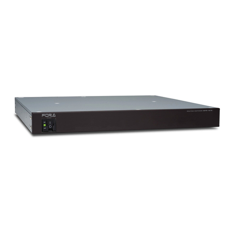
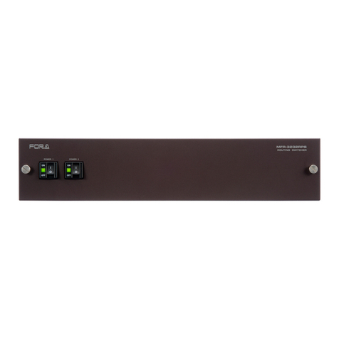
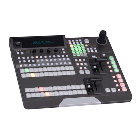
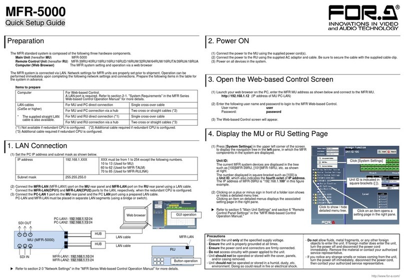
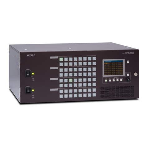
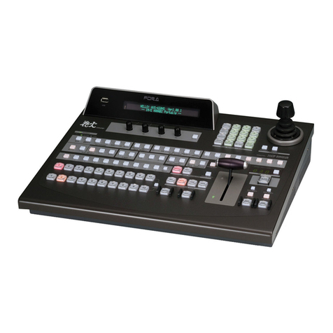
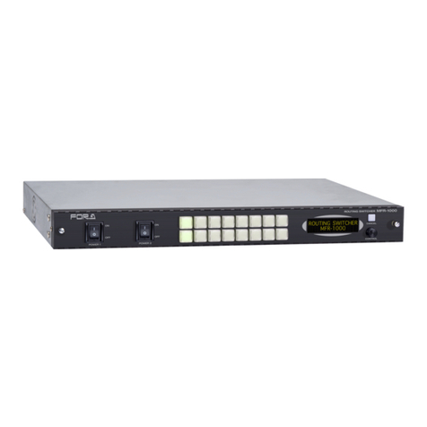
FOR-A MFR-5000 User manual

MFR-5000
Multi Format Routing Switcher
MFR-18/39RUA
MFR-16/18/39/40RU
MFR-16RUD
MFR-16/32/64RUW
MFR-16RUTA
MFR-GPI
MFR-TALM
13th Edition - Rev. 1
OPERATION
MANUAL

2
Edition Revision History
Edit.
Rev.
Date
Description
Section/Page
1
-
2011/11/07
2
|
5
-
(Not released)
Added MFR-16ADI/16ADAO option cards.
Added MFR-18RU.
Added MFR-16RU.
Added MFR-GUI.
6
-
2013/05/22
Added MFR-16AAI/AESI/AESO option cards.
Added MFR-16RUD
Added MFR-TALM.
7
-
2013/08/13
Added MFR-16RUW/32RUW remote units
Changed DC cable retaining clamps
Added Setup menu for RU
Factual errors corrected
p 6
Sec. 5-6
Sec. 5-7
7
1
2013/08/21
Changed power consumption for MFR-GPI,
MFR-16RUD/16RUW/32RUW
Sec. 9-1
7
2
2013/09/10
Manuals supplied on CD-ROM
Changed Setup menu description
Changed MFR-16RUW/32RUW front panels
p 5
Sec. 5-7
Sec. 5-8
Sec. 9-2-7
Sec. 9-2-8
8
-
2013/12/25
Added Main Unit Link function
Added MFR-64RUW.
RU current level is applied to RU Salvos.
Added Group LOCK OTHER function.
3-2
2-2, 9-1-8,
9-2-7, etc.
6-2-2
6-3-2
8
1
2014/03/20
Added CPU2 condition display
Added the max. number of LAN/Serial connections.
Corrected factual errors.
p 22, 49, 52
p 98
9
(Not Rereaced)
9
1
2014/10/24
Supported MFR-16DTIO cards
Enabled group button assignments
Added 2-way Lock buttons (by short and long press)
Added serial control commands.
Sec. 2, 9-1-1
Sec. 5-2-2
Sec. 5-3 to 5-5
Sec. 7-3
10
-
2015/04/06
MFR-16RUTA supported
Changed control command description
Added text color tuning for remote control unit
buttons.
Notes on button labels deletec (uploaded to the HP)
Corrected factual errors.
Sec. 7-3
Sec. 8
Appendix
11
-
2015/06/26
Added Switcher's AUX Crosspoints Switching.
Added Destination Lock Status Request Command.
Sec. 3-4
Sec. 7-3-5
12
-
2015/11/11
MFR-18/39RUA supported.
12
1
2016/04/01
LAN control command added (signal name import)
Sec. 7-3
12
2
2016/09/06
Changed control command description
Sec. 7-3
13
-
2017/02/22
Switcher AUX switching supported (HVS-100/110,
HVS-2000).
Gearbox (MFR-16SDIGB/SDOGB) supported.
Secs. 3-3, 3-4
Secs. 2-1, 2-2,
2-3, 8
13
1
2017/03/01
MFR-16AAIEX/AAOEX suppoerted.
Secs. 2-1, 2-2,
2-4

3
Firmware / Software Versions and Supported Hardware / Features
Main Unit Firmware Version (*1)
GUI Version
(*2)
Supported
Hardware
Supported Feature
MFR-5000
1.62 or higher
1.63 or higher
MFR-64RUW
Main Unit Link
1.72 or higher
1.77 or higher
MFR-16RUTA
-
1.76 or higher
1.85 or higher
-
-MU link of MFR-8000
and 5000
-Switcher's AUX
Crosspoints Switching
1.79 or higher
1.91 or higher
-
-Import names
1.85 or higher
1.98.1 or higher
MFR-16AAIEX
MFR-16AAIOEX
-Analog audio
input/output
1.86 or higher
2.01 or higher
MFR-16SDIGB
MFR-16SDOGB
-Gearbox feature
(*1) Click [Primary CPU] in the [Web-based Control: System Settings- MU Info page] to see your version number
under Firmware Version.
(*2) The GUI (Web-based control software) version is displayed on the browser's title bar.

4
Precautions
Important Safety Warnings
[Power]
Caution
Operate unit only at the specified supply voltage.
Disconnect the power cord via the power plug only. Do not pull on the cable portion.
Stop
Do not place or drop heavy or sharp-edged objects on the power cord. A damaged
cord can cause fire or electrical shock hazards. Regularly check the power cord for
excessive wear or damage to avoid possible fire / electrical hazards.
Caution
Ensure the power cord is firmly plugged into the AC outlet.
[Grounding]
Caution
Ensure the unit is properly grounded at all times to prevent electrical shock.
Hazard
Do not ground the unit to gas lines, units, or fixtures of an explosive or dangerous
nature.
[Operation]
Hazard
Do not operate the unit under hazardous or potentially explosive atmospheric
conditions. Doing so could result in fire, explosion, or other hazardous results.
Hazard
Do not allow liquids, metal pieces, or other foreign materials to enter the unit. Doing
so could result in fire, other hazards, or a unit malfunction.
If a foreign material does enter the unit, turn the power off and immediately
disconnect the power cord. Remove the material and contact an authorized service
representative if damage has occurred.
[Transportation]
Caution
Handle with care to avoid impact shock during transit, which may cause
malfunction. When you need to transport the unit, use the original or suitable
alternative packing material.

5
[Circuitry Access]
Do not remove covers, panels, casing, or access the circuitry with power applied to
the unit. Turn the power off and disconnect the power cord prior to removal. Internal
servicing / adjustment of unit should only be performed by qualified personnel.
Stop
Do not touch any parts / circuitry with a high heat factor.
Capacitors can retain enough electric charge to cause mild to serious shock, even
after the power has been disconnected. Capacitors associated with the power
supply are especially hazardous.
Hazard
Unit should not be operated or stored with cover, panels, and / or casing removed.
Operating the unit with circuitry exposed could result in electric shock / fire hazards
or a unit malfunction.
[Potential Hazards]
Caution
If abnormal odors or noises are noticed coming from the unit, immediately turn the
power off and disconnect the power cord to avoid potentially hazardous conditions.
If problems similar to the above occur, contact an authorized service representative
before attempting to operate the unit again.
[Rack Mount Brackets, Ground Terminal, and Rubber Feet]
Caution
To rack-mount or ground the unit, or to install rubber feet, do not use screws or
materials other than those supplied. Doing so may cause damage to the internal
circuits or components of the unit. If you remove the rubber feet that are attached to
the unit, do not reinsert the screws that secure the rubber feet.
[Consumables]
Caution
Consumable items that are used in the unit must be periodically replaced. For
further details on which parts are consumables and when they should be replaced,
refer to the specifications at the end of the Operation Manual. Since the service life
of the consumables varies greatly depending on the environment in which they are
used, such items should be replaced at an early date. For details on replacing
consumable items, contact your dealer.

6
Upon Receipt
Unpacking
MFR-5000 units and their accessories are fully inspected and adjusted prior to shipment.
Operation can be performed immediately upon completing all required connections and
operational settings.
Check your received items against the packing lists below. Check to ensure no damage has
occurred during shipment. If damage has occurred, or items are missing, inform your supplier
immediately.
Main Unit
ITEM
QTY
REMARKS
MFR-5000
1
AC Cord
1 set
AC cable and retaining clip
Rack Mount Brackets
1 set
EIA standard type (Attached to unit.)
Power Switch Faceplate
1
Switch guard for MFR-PS.
CD-ROM
1
Operation manual (PDF)
Quick Setup Guide
1
Input / Output Cards
ITEM
QTY
REMARKS
MFR-16SDI/16SDIA
1 –8 *
16 SDI input card
MFR-16SDO
1 –8 *
16 SDI output card
MFR-16ADI
1 –4 *
Digital audio input card with SRC
(AES/EBU 16 stereo pairs)
MFR-16AAI
1 –4 *
Analog audio input card with A/D converter
(Analog 16 stereo pairs)
MFR-16ADAO
1 –8 *
Audio output card with D/A converter
(AES/EBU 8 stereo pairs)
(SDI x 2 8 stereo pairs)
(ANALOG 4 stereo pairs)
MFR-16AESI
1 –8 *
Digital audio input card (AES/EBU 16 stereo pairs)
MFR-16AESO
1 –8 *
Digital audio output card (AES/EBU 16 stereo
pairs)
MFR-16DTIO
1 –8 *
Data Router card (9-pin D-sub x 16, RS-422)
MFR-16SDIGB
1 –
16 SDI input card (Gearbox 4ch built-in)
MFR-16SDOGB
1 –
16 SDI output card (Gearbox 4ch built-in)
MFR-16AAIEX
1 –4 *
Analog audio input card with A/D converter
(Analog 16 stereo pairs)
MFR-16AAOEX
1 –4 *
Analog audio output card with D/A converter
(Analog 16 stereo pairs)
* The number of installed cards varies depending on the system configuration. See the Matrix Size Chart
on page 16.
Remote Control Panel
ITEM
QTY
REMARKS
MFR-18RUA/39RUA
MFR-39RU/40RU/18RU
MFR-16RU/16RUD/16RUTA
MFR-16/32/64RUW
1
AC Adaptor (*1)
1
With DC lock plug (MFR-40RU/39RUA/18RUA)
AC cable
1
DC cable retaining clip
1 set
For AC adapters w/o DC lock plug
Rack Mount Brackets
1 set
EIA standard type (MFR-16/32/64RUW/16RUTA is
supplied w/o Rack Mount Brackets.)
Tool used to change
button labels
1

7
LAN Cable (straight) (*2)
1
MFR-39/40/18RU/16RUTA/18RUA/39RUA:
UTP cable, 5m
MFR-16RU/16RUD: STP cable, 5m
(MFR-16/32/64RUW is supplied w/o LAN Cable.)
(*1) Depending on the production date, AC adapter is supplied without DC lock plug, but with a DC cable
retaining clip.
(*2) User-prepared LAN cables are also available and Shielded Twist Pair cables are recommended for
MFR-16RU/16RUD/16RUW/32RUW/64RUW.
Option (for MFR-5000)
ITEM
QTY
REMARKS
MFR-CPU
1
Redundant CPU card *
MFR-PS
1 set
Redundant power supply unit (with AC cord and AC
cord retaining clip.)
Interface Expansion Unit
ITEM
QTY
REMARKS
MFR-GPI
1
AC Adaptor *
1
With DC lock plug
AC cable
1
Rack Mount Brackets
1 set
EIA standard type
LAN Cable (straight)
1
* Depending on the production date, AC adapter is supplied without DC lock plug, but with a DC cable
retaining clip.
Tally Manager Unit
ITEM
QTY
REMARKS
MFR-TALM
1
AC Adaptor *
1
With DC lock plug
AC cable
1
Rack Mount Brackets
(optional)
1 set
Single- or Dual-unit type
EIA standard type
* Depending on the production date, AC adapter is supplied without DC lock plug, but with a DC cable
retaining clip.
Installing the AC Cord Retaining Clip (Main Unit)
Secure the AC cord with the supplied AC cord retaining clip to prevent accidental removal from
the unit.
Procedure
1) Securely plug the AC cord into the AC connector.
2) Attach the Retaining clip on to the side of the AC cord.
3) Thread both ends of the retaining clip into the holes of the retaining clip base attached on the
unit.

8
Installing the DC Cable Retaining Bracket
Install the supplied retaining bracket onto the rear panel of devices, such as a Control Unit as
shown below.
Font Conventions
The following conventions are used throughout this manual:
Shaded text (such as ON) indicates parameter values in the menu.
Text enclosed by a square (such as ALARM, MODE) indicates front panel buttons on the
MFR-5000 or Remote Control Units.
References to the MFR Series Web-based Control Software are indicated by [Web-based
Control: XXX page].
2) Secure the clip with
the supplied screw.
1) Bundle the cable with
the supplied clip.

9
Table of Contents
1. Prior to Starting..........................................................................................................................14
1-1. Welcome ............................................................................................................................14
1-2. Features.............................................................................................................................14
2. Panel Descriptions ....................................................................................................................15
2-1. MFR-5000 Front Panel.......................................................................................................15
2-1-1. Matrix Size Chart.........................................................................................................16
2-1-2. Input / Output Card Installation and Removal.............................................................17
2-1-3. CPU Card Installation and Removal...........................................................................18
2-1-4. CPU Card Switch Settings..........................................................................................20
2-2. MFR-5000 Rear Panel.......................................................................................................21
2-2-1. Interfaces.....................................................................................................................22
2-3. SDI Input/Output Cards......................................................................................................24
2-3-1. MFR-16SDI/16SDIA....................................................................................................24
2-3-2. MFR-16SDO ...............................................................................................................24
2-3-3. MFR-16SDIGB............................................................................................................25
2-3-4. MFR-16SDOGB..........................................................................................................25
2-4. Audio Input / Output Cards.................................................................................................26
2-4-1. MFR-16AAI / 16AAIEX (Analog Input)........................................................................26
2-4-2. MFR-16ADI (AES Input with SRC).............................................................................30
2-4-3. MFR-16ADAO (Embedded / AES / Analog Output)...................................................31
2-4-4. MFR-16AESI (AES Input)...........................................................................................33
2-4-5. MFR-16AESO (AES Output).......................................................................................33
2-5. RS-422 Data Input / Output Cards.....................................................................................34
2-6. Remote Control Panel........................................................................................................36
2-6-1. Front Panel..................................................................................................................36
2-6-2. Rear Panel..................................................................................................................40
2-7. MFR-GPI............................................................................................................................41
2-7-1. Front Panel..................................................................................................................41
2-7-2. Rear Panel..................................................................................................................42
2-7-3. Interfaces (MFR-GPI)..................................................................................................43
2-7-4. Switches on the Card..................................................................................................45
2-8. MFR-TALM.........................................................................................................................46
2-8-1. Front Panel..................................................................................................................46
2-8-2. Rear Panel..................................................................................................................47
3. System Configuration Example.................................................................................................48
3-1. Basic Configuration............................................................................................................48
3-2. Main Unit Linking................................................................................................................49
3-2-1. Parallel Link System Example ....................................................................................49
3-2-2. Expanded Matrix System Example.............................................................................50
3-3. Signal Name and Tally Link System..................................................................................51
3-3-1. Standard Configuration...............................................................................................51
3-3-2. If Configuring an MFR-TALM......................................................................................53
3-4. Switcher's AUX Crosspoints Switching System.................................................................56
3-4-1. Switching an AUX Bus Signal.....................................................................................56
3-4-2. Synchronous Crosspoints Switching ..........................................................................58

10
4. Settings via MFR-5000 Menus..................................................................................................60
4-1. Function List.......................................................................................................................60
4-2. Front Menu Basic Operation..............................................................................................61
4-3. Blinking ALARM Button......................................................................................................62
4-4. Menu Structure...................................................................................................................63
4-5. SETTINGS .........................................................................................................................65
5. Remote control panel Operation...............................................................................................66
5-1. Functions and Operations..................................................................................................66
5-2. Basic Operation on Control Panels....................................................................................67
5-2-1. Buttons........................................................................................................................67
5-2-2. Page Function.............................................................................................................68
5-2-2-1. Group Page Changes..........................................................................................68
5-2-3. Control Knob...............................................................................................................70
5-3. Function Buttons................................................................................................................72
5-4. MODE Button and Mode Menu (MFR-39RU/18RU/16RUTA/39RUA/18RUA).................75
5-4-1. Outline.........................................................................................................................75
5-4-2. Mode Menu.................................................................................................................75
5-4-3. Setting Mode Menu (MFR-39RU)...............................................................................78
5-4-3-1. DEF MODE..........................................................................................................78
5-4-3-2. DEF DEST ...........................................................................................................79
5-4-3-3. DEF LEVEL..........................................................................................................79
5-4-3-4. PAGE MODE.......................................................................................................79
5-4-3-5. PAGE ASSIGN ....................................................................................................79
5-4-3-6. DST INHIBIT........................................................................................................80
5-4-3-7. SRCINHIBIT.........................................................................................................80
5-4-3-8. NAME TYPE........................................................................................................81
5-4-3-9. TENKEY MOD.....................................................................................................81
5-4-3-10. TENKEY NO......................................................................................................81
5-4-3-11. SALVO CLR.......................................................................................................82
5-4-3-12. BTN ASSIGN.....................................................................................................82
5-4-4. Setting Mode Menu (MFR-39RUA).............................................................................84
5-4-4-1. NETWORK...........................................................................................................84
5-4-4-2. VER/ALARM........................................................................................................85
5-4-4-3. DEFAULT.............................................................................................................85
5-4-4-4. BUTTON ASSIGN................................................................................................86
5-4-4-5. INHIBIT ................................................................................................................87
5-4-4-6. NAME TYPE........................................................................................................87
5-4-4-7. BRIGHTNESS......................................................................................................88
5-4-4-8. RU-RU CONNECT...............................................................................................88
5-4-4-9. TENKEY...............................................................................................................88
5-4-4-10. PAGE.................................................................................................................88
5-4-4-11. SALVO CLEAR..................................................................................................88
5-5. Operation Using the Menu Display (MFR-16RUD)............................................................89
5-5-1. Crosspoint Switching ..................................................................................................89
5-5-2. Button Assignment Change........................................................................................90
5-6. Setup Menu (MFR-39RU)..................................................................................................92
5-6-1. IP ADDRESS[RU].......................................................................................................92
5-6-2. SUBNET MASK[RU]...................................................................................................92

11
5-6-3. PC-LAN[MU] ...............................................................................................................93
5-6-4. RU CONN ID...............................................................................................................93
5-6-5. RU CONNECT............................................................................................................94
5-6-6. BRIGHTNESS.............................................................................................................94
5-6-7. BTN ASSIGN ..............................................................................................................94
5-6-8. VER/ALARM ...............................................................................................................94
5-6-9. REBOOT.....................................................................................................................94
5-7. Setup Menu (MFR-39RUA)................................................................................................95
5-8. Setup Menu (MFR-18RU/18RUA) .....................................................................................95
5-8-1. Displaying Network Settings.......................................................................................95
5-8-2. Changing the RU Network Settings............................................................................96
5-8-3. Rebooting MU PC-LAN...............................................................................................96
5-9. Setup Menu (MFR-16RUTA)..............................................................................................97
5-9-1. Displaying Network Settings.......................................................................................97
5-9-2. Changing the RU Network Settings............................................................................98
5-9-3. Rebooting MU PC-LAN...............................................................................................98
5-10. Setup Menu (Other Remote Control Units)......................................................................99
5-10-1. Displaying Network Settings...................................................................................100
5-10-2. Changing the RU IP Address..................................................................................101
5-10-3. Rebooting MU PC-LAN...........................................................................................102
5-11. Multi-Panel Operation ....................................................................................................103
5-11-1. Outline.....................................................................................................................103
5-11-2. Enabling Multi-Panel Operation..............................................................................104
6. Crosspoint Control...................................................................................................................105
6-1. One Crosspoint Switching................................................................................................105
6-1-1. One Crosspoint Switching by X-Y Setting................................................................105
6-1-1-1. SKIP-FWD/BWD................................................................................................106
6-1-1-2. TENKEY (MFR-39RU/39RUA)..........................................................................106
6-1-2. A Crosspoint Switching Using a Bus Button.............................................................107
6-1-3. CHOP Function.........................................................................................................108
6-1-4. Crosspoint Switching Using TAKE Function.............................................................108
6-2. Simultaneous Crosspoint Switching.................................................................................109
6-2-1. Main Unit Stored Salvos ...........................................................................................109
6-2-2. Remote Control Stored Salvos .................................................................................109
6-2-3. Simultaneous Switching Using the Take Function...................................................111
6-2-4. Simultaneous Switching by the Link Function..........................................................111
6-3. Lock..................................................................................................................................111
6-3-1. LOCK LOCAL............................................................................................................111
6-3-2. LOCK OTHER / LOCK ALL ......................................................................................112
6-4. Monitor Output Function...................................................................................................115
6-5. Preview Function..............................................................................................................115
6-6. Level Control....................................................................................................................116
6-6-1. Level Indication on the Remote Control Panel.........................................................117
7. Serial / LAN Command Control...............................................................................................118
7-1. Serial Interface.................................................................................................................118
7-2. LAN Interface ...................................................................................................................118
7-3. Control Commands..........................................................................................................119

12
7-3-1. Command Responses (Commands 1-6)..................................................................120
7-3-2. Receiving Responses (Commands 1-6)...................................................................121
7-3-3. Channel Name Request Commands (7)...................................................................124
7-3-4. CPU Status Request Command (8)..........................................................................128
7-3-5. Destination Lock Status Request Command (9).......................................................129
7-3-6. Channel Name Import Commands (10)....................................................................130
8. Gearbox Feature (MFR-16SDIGB/16SDOGB).......................................................................131
8-1. MFR-16SDIGB / 16SDOGB Cards..................................................................................131
8-2. Available Conversions......................................................................................................132
8-3. Conversion Settings.........................................................................................................132
8-3-1. Converting 3G SQD Input to 2SI (MFR-16SDIGB) ..................................................132
8-3-2. Converting 2SI to SQD Output (MFR-16SDOGB)....................................................133
8-3-3. Converting 12G-SDI Input to 3G-SDI 2SI (MFR-16SDIGB).....................................134
8-3-4. Converting 3G-SDI SQD to 12G-SDI Output (MFR-16SDOGB)..............................134
9. Troubleshooting.......................................................................................................................135
9-1. Tuning the Text Color on Remote Unit Buttons...............................................................136
9-1-1. MFR-18RU/39RU Color Tuning Procedure..............................................................136
9-1-2. MFR-16RUTA/39RUA/18RUA Color Tuning Procedure..........................................137
10. Specifications and Dimensions.............................................................................................138
10-1. Unit Specifications..........................................................................................................138
10-1-1. MFR-5000...............................................................................................................138
10-1-2. MFR-39RUA............................................................................................................141
10-1-3. MFR-39RU..............................................................................................................141
10-1-4. MFR-40RU..............................................................................................................142
10-1-5. MFR-18RUA............................................................................................................142
10-1-6. MFR-18RU..............................................................................................................143
10-1-7. MFR-16RU/16RUD.................................................................................................143
10-1-8. MFR-16RUTA .........................................................................................................144
10-1-9. MFR-16RUW...........................................................................................................144
10-1-10. MFR-32RUW.........................................................................................................145
10-1-11. MFR-64RUW.........................................................................................................145
10-1-12. MFR-GPI...............................................................................................................146
10-1-13. MFR-TALM............................................................................................................146
10-2. External Dimensions......................................................................................................147
10-2-1. MFR-5000...............................................................................................................147
10-2-2. MFR-39RUA............................................................................................................148
10-2-3. MFR-39RU..............................................................................................................148
10-2-4. MFR-40RU..............................................................................................................149
10-2-5. MFR-18RUA............................................................................................................149
10-2-6. MFR-18RU..............................................................................................................150
10-2-7. MFR-16RU..............................................................................................................150
10-2-8. MFR-16RUD ...........................................................................................................151
10-2-9. MFR-16RUTA .........................................................................................................151
10-2-10. MFR-16RUW.........................................................................................................152
10-2-11. MFR-32RUW.........................................................................................................152
10-2-12. MFR-64RUW.........................................................................................................153
10-2-13. MFR-GPI...............................................................................................................153

13
10-2-14. MFR-TALM............................................................................................................154
Appendix: Operation Tips............................................................................................................155
How to use Page buttons........................................................................................................155

14
1. Prior to Starting
1-1. Welcome
Congratulations! By purchasing an MFR-5000 Multi Format Routing Switcher (hereafter called
MFR main unit) you have entered the world of FOR-A and its many innovative products. We
thank you for your patronage and hope you will turn to FOR-A products again and again to
satisfy your video and audio needs.
FOR-A provides a wide range of products, from basic support units to complex system
controllers, which have been increasingly joined by products for computer video-based systems.
Whatever your needs, talk to your FOR-A representative.We will do our best to be of continuing
service to you.
1-2. Features
The MFR-5000 is a multi-format routing switcher that supports 12G-SDI, 3G-SDI, HD-SDI,
SD-SDI, ASI, and AES video / audio signals as well as RS-422 data signals. Inside the 8U case
a matrix of up to 128 inputs/128 outputs can be configured. And by linking multiple cases, they
can be used as a large-scale routing switcher. It supports various functions such as the
capability of linking multiple cases, tally connections with peripheral devices, and automatic
source name tracking, to allow the units to be the core product in small tomedium size systems.
Support for 3G-SDI, HD-SDI, SD-SDI, and ASI signals with automatic signal recognition that
enables operation without concern for the type of signal. Changing the input/output card
enables support for 12G-SDI,AES audio and RS-422 data signals.
By linking multiple units, they can be used as a large-scale routing switcher.
Up to 4 units can be linked together for expansions of up to 256x128 –384x42.
One routing switcher can be virtually partitioned to build any theoretical hierarchy, which
creates possibilities for use in various operating forms.
Various crosspoint control functions such as Salvo, Take, Link, Level operation, and Chop
Tally linking with FOR-A’s video switchers (HANABI Series) and multi viewers. Source
name displays on video switchers and multi viewers can be switched in conjunction with
switchings controlled in the main unit. MFR routers support TSLand Harris protocol, enabling
linkage to other companies' products.
Built-in webserver for remote control through a web browser
SNMP support enabling SNMP monitoring system configuration
Status monitoring for power supply, fan, CPU, SDI input/output, etc.
CPU board redundancy allowing monitoring of primary CPU board operation via the
secondary board. Immediate and smooth switch over to the secondary board without down
time in case of irregularities, as well as stable remote control operation supported by the
network redundancy
Power unit redundancy for stable power supply against power unit failure or power supply
troubles
LED displayon the main unit front that can display settings and alarms enablingthe main unit
to take over operation in the event the remote environment goes down.
Designed for maintainability, all boards and power units can be accessed from the front
without removing any cables connected in back.
Matrix partition and level setting capabilities support a flexible control environment (maximum
of 128 units in total including the main unit)
Remote control panel connectivity for configuring a huge control panel
Interface expansion unit (MFR-GPI) for additional 128 (32 x 4) GPI/O and 4 serial ports (9-pin
D-sub, male)
MFR-TALM Tally Manager Unit is designed specifically to manage tally and signal name data
in the MFR system and the exchange of this data with external devices such as a video
switcher, multiviewer etc.. The unit performs the task of tally data computation, which is
ordinarily undertaken by the MFR main unit, to accelerate the task.
Conversions between 12G-SDI and Quad Link 3G-SDI and between 2SI and SQD available
by installing optional MFR-16SDIGB and MFR-16SDOGB (Gearbox feature built-in) cards.

15
2. Panel Descriptions
2-1. MFR-5000 Front Panel
No.
Name
Description
A
POWER1
Power switch 1 (standard equipment)
(1) Switch to turn unit power On/Off.
(2) DC power supply voltage indication LED
(Normal: lit green / Error: unlit)
B
POWER2 *1
Power switch 2 (optional equipment) (1) and (2) the same as
POWER1.
C
CPU1
CPU card (standard equipment/Primary CPU)
(1) Displays settings and alarms
(2) Alarm button to enter the ALARM menu. Effective during an alarm.
(ALARM button) (The LED lights red in an alarm.)
(3) Cancel button for menu settings.
(ACTIVE/BUS button) (The LED lights green when active)
(4) Used for menu operation (CONTROL knob)
* See section 4 “Settings via MFR-5000 Menus”for details on the menu
operation.
D
CPU2
CPU card (optional/Secondary CPU) (1) to (4) are the same as CPU1.
*1 When installing the second power supply unit, be sure to set PS2 INSTALL to
INSTALLED under SETTING > MU SETTING > PS2 INSTALL in the CPU card front
menu. (See section 4. “Settings via MFR-5000 Menus”)
Input / Output Card Slots
No.
Slot
Video Card
Audio Card
16DTIO Card
E
INPUT 1 - 4
(No. 01 - 04)
16SDI/16SDIA
Max. 4 cards
16AESI: Max. 4 cards
No. 01, 03
Max. 2 cards
INPUT 5 - 8
(No. 05 - 08)
16SDI/16SDIA
Max. 4 cards
16ADI: Max. 4 cards
16AAI: Max. 4 cards
16AAIEX: Max. 4 cards
16AESI: Max. 4 cards
No. 05, 07
Max. 2 cards
F
OUTPUT 1 - 8
(No. 09 - 16)
16SDO
Max. 8 cards.
16ADAO: Max. 8 cards
16AAOEX: Max. 4 cards
16AESO: Max. 8 cards
No. 09, 11, 13, 15
Max. 4 cards
12345678
123456781234567812345678
16 15 14 13 12 11 10 09 08 07 06 05 04 03 02 01 ←Slot No
C
E
F
(1)
(2)
(3)
(4)
D
(1)
(2)
(3)
(4)
A
(1)
(2)
B
(1)
(2)

16
2-1-1. Matrix Size Chart
Standard SDI Signal Routing
Matrix size varies depending on the number of installed MFR-16SDI/16SDIA and
MFR-16SDO cards as shown below. (128 x 128 to 16 x 16)
Number of cards: MFR-16SDO
8
7
6
5
4
3
2
1
Number of
cards:
MFR-16SDI/
16SDIA
8
128 x 128
128 x 112
128 x 96
128 x 80
128 x 64
128 x 48
128 x 32
128 x 16
7
112 x 128
112 x 112
112 x 96
112 x 80
112 x 64
112 x 48
112 x 32
112 x 16
6
96 x 128
96 x 112
96 x 96
96 x 80
96 x 64
96 x 48
96 x 32
96 x 16
5
80 x 128
80 x 112
80 x 96
80 x 80
80 x 64
80 x 48
80 x 32
80 x 16
4
64 x 128
64 x 112
64 x 96
64 x 80
64 x 64
64 x 48
64 x 32
64 x 16
3
48 x 128
48 x 112
48 x 96
48 x 80
48 x 64
48 x 48
48 x 32
48 x 16
2
32 x 128
32 x 112
32 x 96
32 x 80
32 x 64
32 x 48
32 x 32
32 x 16
1
16 x 128
16 x 112
16 x 96
16 x 80
16 x 64
16 x 48
16 x 32
16 x 16
AUDIO Signal Routing
Matrix size varies depending on the number of installed MFR-16ADI, MFR-16AAI and
MFR-16ADAO cards as shown below. (1 stereo pair = 2 channels)
Number of cards: MFR-16ADAO
8
7
6
5
4
3
2
1
Number of
cards:
MFR-16ADI
or
16AAI
4
64 x 64
64 x 56
64 x 48
64 x 40
64 x 32
64 x 24
64 x 16
64 x 8
3
48 x 64
48 x 56
48 x 48
48 x 40
48 x 32
48 x 24
48 x 16
48 x 8
2
32 x 64
32 x 56
32 x 48
32 x 40
32 x 32
32 x 24
32 x 16
32 x 8
1
16 x 64
16 x 56
16 x 48
16 x 40
16 x 32
16 x 24
16 x 16
16 x 8
Matrix size varies depending on the number of installed MFR-16AESI, MFR-16AESO,
MFR-16AAIEX and MFR-16AAOEX cards as shown below. (1 stereo pair = 2 channels)
* Up to 4 cards for MFR-16AAIEX and MFR-16AAOEX cards
Number of cards: MFR-16AESO or 16AAOEX
8
7
6
5
4
3
2
1
Number of
cards:
MFR-
16AESI
or
16AAIEX
8
128 x 128
128 x 112
128 x 96
128 x 80
128 x 64
128 x 48
128 x 32
128 x 16
7
112 x 128
112 x 112
112 x 96
112 x 80
112 x 64
112 x 48
112 x 32
112 x 16
6
96 x 128
96 x 112
96 x 96
96 x 80
96 x 64
96 x 48
96 x 32
96 x 16
5
80 x 128
80 x 112
80 x 96
80 x 80
80 x 64
80 x 48
80 x 32
80 x 16
4
64 x 128
64 x 112
64 x 96
64 x 80
64 x 64
64 x 48
64 x 32
64 x 16
3
48 x 128
48 x 112
48 x 96
48 x 80
48 x 64
48 x 48
48 x 32
48 x 16
2
32 x 128
32 x 112
32 x 96
32 x 80
32 x 64
32 x 48
32 x 32
32 x 16
1
16 x 128
16 x 112
16 x 96
16 x 80
16 x 64
16 x 48
16 x 32
16 x 16
►See section 2-4. "Audio Input / Output Cards" for details on audio input and output cards.
RS-422 Data Routing
Matrix size can be freely selected depending on the number of installed MFR-16DTIO cards,
regardless of their slot location, as shown below.
Number of
MFR-16DTIO
cards
8
7
6
5
4
3
2
1
Number of
RS-422 ports
128
112
96
80
64
48
32
16
Routing
Matrix size can be freely selected depending on the number of installed MFR-16DTIO
cards, regardless of their slot location.
RS-422 data can be routed between ports in the same card or different cards.
See section 2-5. “RS-422 DataInput / Output Cards” for details on input and output port
settings.

17
2-1-2. Input / Output Card Installation and Removal
MFR input/output cards should be installed by opening the MFR-5000 front panel. Remove
the four screws on the front panel as shown below to open the front panel.
Removing an MFR Input/Output card
To remove an input or output card with the MFR-5000 powered on, turn the power of the
slot from which to remove the card OFF. Be sure to turn the power of the slot off before
removing its card.
►See [SHUTDOWN] in section 4-5. “SETTINGS.”
Installing an MFR Input/Output card
To install an MFR option card with the MFR-5000 powered on, turn the power of the slot
on, using the front menu, after installing the card.
►See [SHUTDOWN] in section 4-5. “SETTINGS.”
MFR cards must be installed into their respective designated slots from the correct side.
►See section 2-1. “MFR-5000 Front Panel.”
POWE R 2
MFR-500 0
POWE R 1
ON
OFF
ON
OFF
ACTIVE
CPU 1
ALAR M ALA RM ACTIVE
CPU 2
MESSA GE/ME NUMESSA GE/ME NU
ROUTINGSWITCHER

18
2-1-3. CPU Card Installation and Removal
CPU cardscan be installed or removed with the MFR-5000 power turned on as shown below.
IMPORTANT
Do not touch any other parts on the card. Static electricity may damage sensitive
electrical components on the card.
Removing a CPU card
(1)Press the reset button (S1) on the CPU card.
(2)Repress and hold the button, then turn ON the switch 2 of Dipswitch S2.
(3)Release the button. The menu display will turn off automatically.
(4)Hold the two black handles at both sides on the CPU card and gradually remove the card
from the chassis.
Front
S2
8
7
6
5
4
3
2
1
OFF
ON
S1
422
422
232C
232C
S4
S3

19
Inserting a CPU card
(1)Verify that the switch 2 of Dipswitch S2 on the card is turned OFF.
If not, turn the switch to OFF.
(2)If the installed CPU card is not active (ACTIVE/BUSY lights green.), wait for 20 seconds.
(3)Align a new CPU card with the slot guide rails and insert the card into the slot.
(4)Verify that the card is firmly installed.
Front
S2
8
7
6
5
4
3
2
1
OFF
ON
S1
422
422
232C
232C
S4
S3
ACTIVE/BUSY button

20
2-1-4. CPU Card Switch Settings
IMPORTANT
Note that internal switch settings should only be performed by qualified technical
personnel.
(1)Remove the 4 screws on the MFR-5000 front panel to remove the panel.
(2)The CPU card factory default settings are as shown below.
Switch settings
Switch
Settings
S1
Reset switch for the CPU card.
S2
For maintenance use. Do not change
these settings except when removing
the CPU card. (Factory default
settings are as shown in the right
figure. The black squares (■) depict
the switch positions.)
S3, S4
Used to select RS-232C or RS-422.
Make your selection referring to the
right figures. Both switches must be
set the same.
CPU1 and CPU2 must use the same
settings.
Switch
settings
RS-232C
(Factory default)
RS-422
►See section 2-1-3. “CPU Card Installation and Removal”to remove a CPU card.
Front
S2
8
7
6
5
4
3
2
1
OFF
ON
S1
422
422
232C
232C
S4
S3
OFF
ON
POWE R 2
MFR-500 0
POWE R 1
ON
OFF
ON
OFF
ACTIVE
CPU 1
ALAR M ALA RM ACTIVE
CPU 2
MESSA GE/ME NUMESSA GE/ME NU
ROUTINGSWITCHER
Other manuals for MFR-5000
1
This manual suits for next models
13
Table of contents
Other FOR-A Switch manuals

FOR-A
FOR-A VSF-6496 User manual

FOR-A
FOR-A VSF-1616 User manual

FOR-A
FOR-A MFR Series User manual

FOR-A
FOR-A MFR-3232 User manual

FOR-A
FOR-A Multi Viewer MV-40F(A) User manual

FOR-A
FOR-A RS-HD808 User manual

FOR-A
FOR-A HVS-490 User manual

FOR-A
FOR-A HVS-490 User manual

FOR-A
FOR-A HVS-190S User manual

FOR-A
FOR-A HVS-AUX8 User manual

FOR-A
FOR-A HVS-390HS User manual

FOR-A
FOR-A MFR-6100 User manual

FOR-A
FOR-A MFR-4000 User manual

FOR-A
FOR-A HVS-350HS User manual

FOR-A
FOR-A MFR-5000 User manual

FOR-A
FOR-A HVS-3800HS User manual

FOR-A
FOR-A MFR-6000 User manual

FOR-A
FOR-A MFR-4000R User manual

FOR-A
FOR-A MFR-6100 User manual

FOR-A
FOR-A HVS-1000HS User manual