Forch 5375 9 User manual

Altöl-Absaug- u.
Altöl-Absaug- u.
Sammelgerät 90 l
Sammelgerät 90 l
Bedienungsanleitung
GER
DAN
FRE
ENG
POL
ITA
Recuperatore-aspiratore combinato per olio esausto
Recuperateur/aspirateur d’huile combiné
Kombineret spildoliesuger/samler
Urządzenie do odsysania i przechowywania
zużytego oleju 90 l
Combined waste oil suction/drainer
Art.-Nr. 5375 9
047/GP/BJ/JK 6
SPA
Aspirador-recuperador para aceite usado de 90 l
CZE
Zařízení na odsávání a sběr starého oleje 90 l
5375 9_ Bedienan. Alt lAbsaugSammelgr t:Bedienan. Alt lAbsaugSammelgr t 53759.qxd 18.04.2007 14:09 Seite 5

ACHTUNG!!!
Niemals korrosive oder leicht entflammbare Flüssigkeiten ansaugen. Setzen Sie den Tank niemals
einer Hitzequelle aus. Führen Sie keine Schweißarbeiten am Tank durch. Schützen Sie Hände und
Gesicht, falls Sie Öle mit besonders hohen Temperaturen ansaugen. Benutzen Sie das Gerät mit Vorsicht und nur
zu dem dafür vorgesehenen Zweck. Verändern Sie keine Bestandteile des Gerätes.Verwenden Sie nur
Originalersatzteile. Unsere Technikabteilung steht Ihnen jederzeit für Auskünfte zur Verfügung.
ACHTUNG!!!
Bei einigen Fahrzeugen der Marke MERCEDES ist die Sonde zum Absaugen des Motorenöls bereits
eingebaut.Es ist daher ausreichend, den Schnellverbinder B des Aspiroil direkt an diese anzuschließen.
Bei anderen Fahrzeugtypen (Volkswagen-BMW- Citroën) mit eingebauter Sonde, aber unter-schiedlicher
Öffnung, verwenden Sie bitte den Zwischenadapter (C-Volkswagen,D-BMW,E- Citroën).
GER
ATTENZIONE!!!
Non aspirare liquidi corrosivi o infiammabili. Non esporre il serbatoio a sorgenti di calore. Non
eseguire saldature sul serbatoio. Aspirando olio particolarmente caldo, proteggersi il viso e le mani.
Utilizzare l'apparecchio con cura e solamente per l'utilizzo per cui è stato previsto. Non modificare i
componenti dell'apparecchio. Utilizzare solo parti di ricambio originali. Il nostro ufficio tecnico è a Vostra
disposizione per ogni ulteriore informazione.
ATTENZIONE!!!
Alcune vetture Mercedes hanno già incorporata la sonda per aspirare l'olio motore. Basta quindi
collegare direttamente a questa l'attacco rapido B dell'aspiratore olio.
Per eventuali altre vetture (Volkswagen - BMW - Citroën) con sonda incorporata, ma con imboccatura
differente, utilizzare il relativo connettore adatto (p. es. C per Volkswagen, D per BMW, E per Citroën).
ATTENTION!!!
Ne pas aspirer des liquides corrosifs ou inflammables. Ne pas exposer le réservoir à des sources de
chaleur. Ne pas exécuter des soudages sur le réservoir. En aspirant des huiles très chaudes, se
protéger le visage et les mains. Utiliser l'équipement avec soin et seulement pour l'utilisation pour
laquelle il a été projeté. Ne pas modifier les pièces qui composent l'appareil. Utiliser seulement les pièces de
rechange originelles. Nos bureaux techniques sont à votre disposition pour tous vos besoins.
ATTENTION!!!
Quelques modèles de voitures Mercedes, sont déjà équipés d'une sonde d'aspiration d'huile incorporée au moteur.
Il suffit donc de raccorder directement B à cette sonde. Pour d'autres voitures (Volkswagen - BMW -Citroën) avec
sonde incorporée, ayant une ouverture différente, utiliser le connecteur (C -Volkswagen,D - BMW, E -Citroën).
ADVARSEL!
Foretag ikke opsugning af ætsende eller brandfarlige væsker. Beholderen må ikke udsættes for høje
temperaturer. Der må ikke foretages svejsning på beholderen. Ved aftapning af varm olie skal ansigt
og hænder beskyttes. Vær forsigtig i forbindelse med anvendelse af apparatet, og anvend det kun til
de af fabrikanten påtænkte formål. Anvend kun originale reservedele. Vores tekniske afdeling er til disposition med
yderligere oplysninger.
ADVARSEL!
Visse Mercedes modeller er på forhånd udstyret med en sonde til opsugning af motorolie. Det er derfor tilstrækkeligt
at foretage tilslutning af sugeslangen direkte til lynkoblingen B. Med hensyn til andre modeller (Volkswagen - BMW -
Citroën) med indbygget sonde med en ændret studs, anvendes muffen (C - Volkswagen, D - BMW, E -Citroën).
WARNING!!!
Do not extract caustic or flammable products. Do not expose the reservoir to any source of heat. Do
not do any welding on the reservoir. While extracting high temperature oils, keep hands and face
protected. Only use the device for the purpose for which it has been designed. Do not modify any
component of the equipment. Only use original spare parts. Our technical office is at your full disposal for any
information you may need.
ATTENTION!!!
Some cars have a built-in oil suction probe. In this case, connect the coupler of the oil changer B directly to the
probe. For other makes of car (Volkswagen - BMW - Citroën) equipped with a built-in probe having a
different opening, connector (C - Volkswagen, D -BMW, E - Citroën) must be used.
ITA
FRE
DAN
ENG
047/GP/BJ/JK 7
POZOR!!!
Nenasávejte nikdy korozivní nebo snadno vznětlivé kapaliny. Nevystavujte nádrž nikdy zdroji horka.
Neprovádějte na nádrži svářečské práce. Chraňte si ruce a obličej, pokud nasáváte oleje s obzvláště
vysokými teplotami. Používejte přístroj opatrně a pouze k určenému účelu. Neprovádějte žádné změny
na jednotlivých komponentách přístroje. Používejte pouze originální náhradní díly. S případnými dotazy se obracejte
na naše technické oddělení.
POZOR!!!
Některá vozidla značky MERCEDES mají sondu k odsávání motorového oleje již vestavěnu. Proto postačí
připojit rychlospojku B pro odsávání oleje přímo k sondě. U jiných typů vozidel (Volkswagen, BMW, Citroën)
s vestavěnou sondou, ale jiným otvorem použijte prosím odsávací adaptér (C - Volkswagen, D - BMW, E - Citroën).
UWAGA!!!
Nie należy nigdy zasysać cieczy korozyjnych lub łatwopalnych. Nie należy nigdy wystawiać zbiornika
na działanie wysokiej temperatury. Nie wolno wykonywać na zbiorniku żadnych prac spawalniczych.
Należy chronić ręce i twarz podczas zasysania olejów o szczególnie wysokiej temperaturze. Przy
stosowaniu urządzenia należy zachować ostrożność i używać go jedynie zgodnie z przeznaczeniem. Nie wolno
przerabiać żadnej z części składowych urządzenia. Należy używać jedynie oryginalnych części zamiennych. Nasz
dział techniczny chętnie udzieli Państwu wszelkich potrzebnych informacji.
UWAGA!!!
W niektórych samochodach marki Mercedes sondą do odsysania oleju silnikowego jest montowana fabrycznie.
W takim przypadku wystarczy podłączyć bezpośrednio do niej łącznik B. W innych typach samochodów
(Volkswagen, BMW, Citroen) z wbudowaną sonda, ale o innym rozmiarze otworów, należy użyć odpowiedniej
przystawki (C Volkswagen, DBMW, ECitroen).
CZE
POL
¡ATENCIÓN!
Nunca deben aspirarse líquidos corrosivos o sumamente inflamables.
No debe exponerse el tanque al calor. Nunca debe realizarse ningún tipo de soldadura en el tanque.
Al aspirar aceite de alta temperatura deben protegerse la cara y las manos. Debe utilizarse el aparato con mucho
cuidado y sólo para su uso previsto. No modifique ningún componente del aparato. Para cualquier información no
dude en contactar con nuestro departamento técnico.
¡ATENCIÓN!
Algunos vehículos de la marca MERCEDES ya disponen de una sonda para aspirar aceites de motor. Por eso es
suficiente conectar el conector rápido B de la aspiradora a la sonda. En el caso de otro tipo de automóviles
(VW - BMW - Citroën) que dispongan de una sola sonda con aberturas diferentes, debe utilizarse un adaptador
(C-VW, D-BMW, E- Citroën).
SPA
5375 9_ Bedienan. Alt lAbsaugSammelgr t:Bedienan. Alt lAbsaugSammelgr t 53759.qxd 18.04.2007 14:09 Seite 6

MONTAGE
Abb. 1 - Den Handgriff in die entsprechenden Sitze einfügen und anschließend mit
den Schrauben blockieren. Die Rohrblockierzange Ebefestigen und die
Werkzeugträgerwanne Dpositionieren.
Abb. 2 - Das Venturi-Aggregat auf den Tank montieren und sicherstellen, daß die Dichtung
sich auf der Kupplung befindet. Die Zwinge anziehen und mit einem Hakenschlüssel blockieren.
Abb. 3 - Prüfen, ob der Schnellverbinder A des Gerätes mit den Schnellverbindern Ihrer
Druckluftanlage übereinstimmt. Eventuell das Anschlußstück Ades Gerätes gegen einen
geeigneten Typ mit Außengewinde 1/4" austauschen.
Abb. 4 - Den Entleerungsschlauch am Gummiträgerteil des Hahns aufstecken und mit der
mitgelieferten Schlauchklemme Cbefestigen.
GER
MONTAGGIO
Fig. 1 - Inserire il manico nelle apposite sedi, quindi bloccarlo con le viti. Fissare la
pinza bloccatubo E e posizionare la vaschetta porta utensili D
Fig. 2 - Montare il gruppo Venturi sul serbatoio verificando la presenza della
guarnizione sul giunto; avvitare la ghiera e bloccarla con una chiave a settore.
Fig. 3 - Verificare se il raccordo rapido Adell'apparecchio è compatibile con i raccordi rapidi
del Vostro impianto di aria compressa. Eventualmente sostituire il raccordo Adell'apparecchio
con un tipo idoneo avente filettatura maschio da 1/4".
Fig. 4 - Montare il tubo di scarico sul portagomma del rubinetto e fissarlo con la fascetta strin-
gitubo Cfornita a corredo.
ASSEMBLAGE
Fig. 1 - Insérer l'anse dans son logement et la fixer avec les vis. Fixer la pince E
- Positionner sur son support le bac porte outils D.
Fig. 2 - Monter le groupe d'aspiration sur le réservoir. S'assurer qu'il y ait la
garniture. Visser le collier à l'aide d'une clef.
Fig. 3 - Vérifier que le raccord rapide A de l'Aspiroil corresponde aux raccords rapides de votre
installation à air comprimé. Remplacer éventuellement les raccords avec un raccord fileté 1/4".
Fig. 4 - Monter le tuyau de vidange sur le support du robinet Fixer le tuyau à l'aide d'une bande
métallique C livrée avec l'appareil.
MONTERING
Fig. 1 - Sæt håndtaget ned i holderne på beholderen, og spænd fast med skruerne.
Fastgør slangeholderen E. Anbring værktøjsbakken Di beslaget.
Fig. 2 - Fastgør Venturi enheden til beholderen. Sørg for at pakningen er anbragt korrekt. Stram
tilspændingsmøtrikken med en passende skruenøgle.
Fig. 3 - Kontrollér, at lynkoblingen Aer kompatibel med lynkoblingerne på Deres trykluftssystem.
Såfremt dette ikke er tilfældet, udskiftes apparatets lynkobling Amed en 1/4" kobling med han-
stik af tilsvarende type.
Fig. 4 - Forbind aftapningsslangen med kugleventilen nederst på beholderen, og stram spænd-
båndet Csom følger med.
MONTAŻ
Ryc.1 Uchwyt wpuścić w miejsca osadzenia i następnie zablokować śrubami.
Zamocować rurowy zacisk blokujący E i ustawić wannę suportu narzędziowego D.
Ryc.2 Zamontować agregat Venturi na zbiorniku i sprawdzić, czy uszczelka znajduje się na
sprzęgle. Zaciągnąć zacisk i zablokować kluczem hakowym.
Ryc.3 Sprawdzić czy łącznik Aurządzenia jest zgodny z łącznikami urządzenia
pneumatycznego. Ewentualnie należy wymienić złączkę Aurządzenia na inny odpowiedni typ z
gwintem zewnętrznym 1 / 4 ''.
Ryc. 4 Wąż opróżniający nasadzić na gumową część dźwigarową kurka i zamocować za
pomocą załączonego zacisku do węża C.
ASSEMBLY
Fig. 1 - Insert the handle into its seat and secure it with the screws provided. Attach
the hose clamp retainer E. Position the tool tray D.
Fig. 2 - Attach the Venturi group to the tank. Make sure the gasket is properly positioned. Tighten
the ring nut using a suitable wrench.
Fig. 3 - Check to see if the male adapter Asupplied with the unit, is compatible with your shop
air system's quick coupler. If it is not, replace it with a suitable 1/4" male adapter.
Fig. 4 - Connect the drain hose to the ball valve on the base of the unit's tank and tighten with
the hose clamp Cprovided.
ITA
FRE
DAN
POL
ENG
047/GP/BJ/JK 8
MONTAJE
Imagen 1 - Debe introducirse el mango en los agujeros adecuados y a continuaci-
ón debe fijarse con tornillos. Después debe colocar la bandeja portaherramientas D
en el soporte. Fijar el portamangueras E.
Imagen 2 - Montar el sistema Venturi en el tanque y asegurarse de que la junta esté encima del
emplame. Fijar la tuerca con una llave para tuercas ranuradas.
Imagen 3 - Debe controlarse si el conector rápido Ade su aparato corresponde con los conec-
tores rápidos de su equipo de aire comprimido. En caso necesario debe sustituirse el conector A
del aparato por uno adecuado con una rosca exterior 1/4".
Imagen 4 - Conectar la manguera de vaciado al grifo y fijarla con la abrazadera Csuministrada.
SPA
MONTÁŽ
Obr. 1 - Zasuňte držadlo do příslušných úchytek a poté je zajistěte dodanými
šrouby. Připevněte vidlici Epro uchycení hadice a misku na nářadí D.
Obr. 2 - Přimontujte k nádrži Venturiho trubici a ujistěte se, že těsnění je v místě spojení řádně
usazeno. Utáhněte objímku za použití hákového klíče.
Obr. 3 - Zkontrolujte, zda je rychlospojka Apřístroje kompatibilní s rychlospojkami Vašeho
tlakovzdušného zařízení. Případně vyměňte rychlospojku Apřístroje za vhodný typ s vnějším
závitem 1/4".
Obr. 4 - Nastrčte vypouštěcí hadici na ventil v dolní části nádrže a připevněte ji dodanou
hadicovou sponou C.
CZE
5375 9_ Bedienan. Alt lAbsaugSammelgr t:Bedienan. Alt lAbsaugSammelgr t 53759.qxd 18.04.2007 14:09 Seite 7

Abb. 5 - Das Aggregat Qan den Behälter Pschrauben und gut befestigen. Dann in der
angegebenen Reihenfolge das so erhaltene Aggregat in die Stütze des Tanks einführen.
Abb. 6 - Die Zwinge Mbefestigen. Den Stop-Punkt Npositionieren und mit den mitgelieferten
Schrauben so befestigen, daß der Behälter das Venturi-Aggregat nicht sperrt.
Abb. 7 - Den biegsamen Sammelschlauch mit dem starren Rohr Averbinden und mit den hierfür vorgese-
henen, mitgelieferten Schlauchklemmen befestigen.
Abb. 8 - Den Entleerungsschlauch am Gummiträgerteil des Hahns aufstecken und mit der mitgelieferten
Schlauchklemme befestigen.
Abb. 10 - Den Hahn Gschließen.
GER
Fig. 5 - Avvitare alla vasca Pil gruppo Qfissandolo con forza. Inserire poi, nella sequenza
indicata, il gruppo ottenuto nel supporto del serbatoio.
Fig. 6 - Fissare la ghiera M. Posizionare lo STOP Nfissandolo con le viti in dotazione in
modo che la vaschetta non vada ad intercettare il gruppo Venturi.
Fig. 7 - Collegare il tubo di raccolta flessibile al tubo rigido Afissandolo con le apposite fascette.
Fig. 8 - Montare il tubo di scarico sul portagomma fissandolo con la fascetta in dotazione.
Fig. 10 - Chiudere il rubinetto G.
Fig. 5 - Visser avec force au bassin Ple groupe Q. Ensuite monter, selon la séquence
indiquée, le groupe dans le support du réservoir.
Fig. 6 - Serrer la fosse bonde M. Positionner ensuite le stop Nen le fixant avec les vis en
dotation de façon à ce que le bassin ne touche pas le groupe d'aspiration.
Fig.7 - Fixer le tuyau de vidange flexible au tuyau rigide Aen utilisant la bande métallique en dotation.
Fig.8- Monter le tuyau de vidange sur le support en caoutchouc et le fixer en utilisant la bande métallique
en dotation.
Fig. 10 - Fermer le robinet G.
Fig. 5 - Fastspænd spildoliebakken Ptil enheden Q. Indsæt derefter i den nævnte rækkefølge
enheden i beholderens støtte.
Fig. 6 - Fastgør tilspændingsmøtrikken M. Anbring stoppet N, og fastgør ved hjælp af de medleverede
skruer, således at beholderen ikke kommer i berøring med Venturi enheden.
Fig. 7 - Slut slangen til røret Aved hjælp af klemmerne.
Fig. 8 - Forbind aftapningsslangen med kugleventilen nederst på beholderen, og stram med det
medfølgende spændbånd.
Fig. 10 - Luk hanen G.
Ryc. 5 Przykręcić agregat Qdo zbiornika Pi dobrze dokręcić. Następnie wg podanej
kolejności wprowadzić otrzymany w ten sposób agregat do wspornika zbiornika.
Ryc. 6 Zamocować zacisk M. Ustawić punkt Stop Ni za pomocą załączonej śruby zamocować w ten
sposób, żeby zbiornik nie zamykał agregatu Venturi.
Ryc. 7 Połączyć giętki wąż zbierakowy ze sztywną rurą Ai zamocować załączonymi zaciskami
przeznaczonymi do tego celu.
Ryc. 8 Wąż opróżniający nałożyć na gumową część dźwigarową kurka i zamocować z użyciem
dołączonego zacisku do węża.
Ryc. 10 Zamknąć kurek G.
Fig. 5 - Connect the basin Pto the group Q. Then insert the whole group in its support on the
reservoir.
Fig. 6 - Tighten the ring M. Position the STOP ring N, fixing it with the screws provided, so
that it does not come into contact with the suction group.
Fig. 7 - Connect the flexible drain hose to the rigid one Aand fix it with the hose clamp.
Fig. 8 - Connect the drain hose to the ball valve on the base of the unit's tank and tighten with the hose
clamp provided.
Fig. 10 - Close the ball valve G.
ITA
FRE
DAN
POL
ENG
047/GP/BJ/JK 9
Obr. 5 - Přišroubujte agregát Q k sběrné vaněP a dobře utáhněte. Poté v uvedeném pořadí
zasuňte agregát s vanou do úchytky na nádrži.
Obr. 6 - Utáhněte objímku M. Pomocí dodaných šroubůpřišroubujte kroužek označující polohu STOP N
tak, aby vana nepřekážela Venturiho trubici.
Obr. 7 - Spojte ohebnou sběrnou hadici s pevnou trubkou Aa připevněte ji k tomu určenými hadicovými
sponami, které jsou součástí dodávky.
Obr. 8 - Nastrčte vypouštěcí hadici na ventil v dolní části nádrže a připevněte ji dodanou hadicovou sponou.
Obr. 10 - Zavřete kohout G.
CZE
Imagen 5 - Conectar el elemento Qcon el recipiente Py fijarlo bien. A continuación debe
introducirse el nuevo elemento en el soporte del tanque.
Imagen 6 - Fijar la tuerca M. Posicionar el anillo STOP Ncon los tornillos suministrados de tal manera que
el recipiente no toque el sistema Venturi.
Imagen 7 - Conectar la manguera flexible con el tubo rígido Ay fijarlos con las abrazaderas suministradas.
Imagen 8 - Fijar la manguera de vaciado con la abrazadera suministrada.
Imagen 10 - Cerrar el grifo.
SPA
5375 9_ Bedienan. Alt lAbsaugSammelgr t:Bedienan. Alt lAbsaugSammelgr t 53759.qxd 18.04.2007 14:09 Seite 8

INBETRIEBNAHME ZUM AUFFANGEN VON ÖL
(Abb. 11-12)
Das Gerät unter das auf der Hebebühne befindliche Fahrzeug stellen und die
Wanne so nah wie möglich an den Ablaßpunkt bringen.
Das Altöl auffangen. Wird das Ventil Voffen gelassen, wird das Öl direkt in den Tank eingelas-
sen. Wird das Ventil Vdagegen geschlossen, bleibt das Öl zur eventuellen Inspektion in der
Wanne.
GER
MESSA IN FUNZIONE PER RECUPERO OLIO
(fig. 11-12)
Posizionare l'apparecchio sotto la vettura posta su ponte e regolare la coppa il più
vicino possibile al punto di scarico. Recuperare l'olio esausto.
Lasciando aperta la valvola VI'olio verrà incamerato direttamente dentro al serbatoio.
Chiudendo invece la valvola VI'olio rimarrà nella coppa per eventuale ispezione.
MISE EN FONCTION POUR LA RÉCUPÉRATION
(fig. 11-12)
Positionner l'appareil au-dessous de la voiture montée sur un pont et approcher le
plus possible la cuve au point de décharge. Récupérer toute l'huile. Si on laisse ouverte la valve
V, l'huile descendra directement dans le réservoir.
Si on ferme cette valve, I'huile restera dans la cuve pour une éventuelle inspection.
FORBEREDELSE TIL OPSAMLING AF OLIE
(fig. 11-12)
Anbring apparatet under en ophejst bil, og anbring spildoliesamleren så tæt som
muligt på tømningsstedet. Opsaml den anvendte olie.
Hvis ventilen Ver åben, vil olien blive tappet direkte ned i hovedbeholderen.
Hvis ventilen Ver lukket, forbliver olien i spildoliebakken for eventuel kontrol.
URUCHOMIENIE W CELU SPUSTU OLEJU
(Ryc. 1112)
Urządzenie ustawić pod znajdującym się na podnośniku pojazdem i umieścić
wannę jak najbliżej punktu spustowego. Zebrać zużyty olej. Przy otwartym wentylu Volej
spłynie bezposrednio do zbiornika. Przy zamkniętym wentylu Volej pozostanie do
ewentualnego sprawdzenia w wannie.
SETTING UP THE OlL DRAINER
(fig. 11-12)
Position the oil drainer under a car mounted on a lift and drain the waste oil. If the
ball valve Vis open, the oil with be drained directly into the main reservoir.
If this valve is closed the oil will remain in the basin for inspection.
ITA
FRE
DAN
POL
ENG
047/GP/BJ/JK 10
UVEDENÍ ZAŘÍZENÍ DO PROVOZU - SBĚR OLEJE
(Obr. 11 - 12)
Umístěte zařízení pod vozidlo na zvedací plošinětak, aby sběrná vana byla místu
vypouštění oleje co nejblíže.
Zachyťte starý olej. Pokud ventil V ponecháte otevřený, olej odtéká přímo do nádrže. Jestliže
však ventil V zavřete, zůstává olej ve vaněpro případnou kontrolu.
CZE
IPUESTA EN SERVICIO PARA RECOGER ACEITE (Imágenes 11-12)
Poner el aparato debajo del vehículo situado en una plataforma elevadora.
Posicionar el recipiente lo más cerca posible de la salida del aceite. Recoger el
aceite usado.
Si la válvula Vestá abierta entonces el aceite llega diréctamente al tanque. Si la válvula está
cerrada el aceite se queda en el recipiente para una posible inspección.
SPA
5375 9_ Bedienan. Alt lAbsaugSammelgr t:Bedienan. Alt lAbsaugSammelgr t 53759.qxd 18.04.2007 14:09 Seite 9

INBETRIEBNAHME ZUR ÖLABSAUGUNG
Abb. 13 - Das Ventil Bdurch Drehen gegen den Uhrzeigersinn vollständig öffnen.
Abb.14- Das Ventil Vschließen.
Abb. 15 - Den Hahn Cschließen.
Abb. 16 - Das Ventil Dschließen.
Abb. 17 - Den Hahn Gschließen.
Abb. 18 - Die Druckluft (7 Bar) an die Schnellverbindung Aanschließen.
Am Schalldämpfer entweicht reichlich Luft. Wenn der Zeiger des Vakuummeters sich dem roten Bereich
nähert (ca. 2,5 - 3 Minuten danach), den Druckluftschlauch abkuppeln. In dem Gerät ist nun Unterdruck
aufgebaut, und es ist bereit zur autonomen Absaugung des Altöls.
GER
MESSA IN FUNZIONE PER ASPIRAZIONE OLIO
Fig. 13 - Aprire totalmenle la valvola Bgirandola in senso antiorario
Fig. 14 - Chiudere la valvola V
Fig. 15 - Chiudere il rubinetto C
Fig. 16 - Chiudere la valvola D
Fig. 17 - Chiudere il rubinetto G
Fig. 18 - Collegare l'aria compressa (7 bar) al raccordo rapido A.
Uscirà abbondante aria dal silenziatore. Quando la lancetta del vuotometro si avvicinerà al campo rosso
(circa 2,5 - 3 min. dopo) staccare l'aria compressa.
L'apparecchio è ora depressurizzato e pronto per un'aspirazione autonoma dell'olio esausto.
MISE EN FONCTION
Fig. 13 - Ouvrir complètement la valve Ben tournant la poignée dans le sens contraire aux
aiguilles d'une montre.
Fig. 14 - Fermer la valve V
Fig. 15 - Fermer le robinet C
Fig. 16 - Fermer la valve D.
Fig. 17 - Fermer le robinet G.
Fig.18 - Brancher l'air (pression optimale 7 bar) au raccord rapide A.
Beaucoup d'air sortira du silencieux. Quand le repère du vidéomètre s'approche du champ rouge (après
environ 2 - 3 min) débrancher l'air comprimé. L'appareil est ainsi dépressurisé et prêt à l'utilisation sans
branchement continu au réseau d'air.
AKTIVERING AF OLIESUGNING
Fig. 13 - Åbn ventil Bhelt ved at dreje mod uret.
Fig. 14 - Luk ventil V.
Fig. 15 - Luk hanen C.
Fig. 16 - Luk lufthanen D.
Fig. 17 - Luk hanen G.
Fig. 18 - Tilkobl trykluft (7 bar) til lynkoblingen A.
Herefter strømmer luften godt ud af lyddæmperen. Når viseren på vakuummeteret nærmer sig det røde
område (ca. 2,5-3 minutter senere), frakobles trykluften.
Trykket er fjernet fra apparatet, som herefter er klart til separat oliesugning.
URUCHOMIENIE W CELU ODSYSANIA OLEJU
Ryc. 13 Otworzyć całkowicie wentyl Bpoprzez obracanie w kierunku przeciwnym do
kierunku ruchu wskazówek zegara.
Ryc. 14 Zamknąć wentyl V.
Ryc. 15 Zakręcić kurek C.
Ryc. 16 Zamknąć wentyl D.
Ryc. 17 Zakręcić kurek G.
Ryc. 18 Podłączyć sprężone powietrze (7 barów) do łącznika A.
Na tłumiku ulatnia się dużą ilość powietrza. Gdy wskazówka próżniomierza zbliży się do obszaru
oznaczonego na czerwono (po ok. 2,5 3 minutach) odłączyć wąż ze sprężonym powietrzem.
W urządzeniu wytworzyło się podciśnienie i jest gotowe do odsysania zużytego oleju.
ACTIVATION FOR OIL SUCTION
Fig. 13 - Open completely valve Bby turning it counter clockwise
Fig. 14 - Close valve V.
Fig. 15 - Close the suction (ball) valve C.
Fig. 16 - Hand tighten (close) the air valve Dby turning it clockwise.
Fig. 17 - Close the valve Gby turning it 90 degrees.
Fig. 18 - Connect shop air (100 psi - 7 bar) to male adaptor A.
Air will flow through the muffler until the gauge approaches the red field (after 2,5 - 3 min.).
Disconnect the shop air. The unit is now depressurized and ready for use.
ITA
FRE
DAN
POL
ENG
047/GP/BJ/JK 11
UVEDENÍ ZAŘÍZENÍ DO PROVOZU - ODSÁVÁNÍ OLEJE
Obr. 13 - Otevřete úplně ventil Botáčením proti směru hodinových ručiček.
Obr. 14 - Zavřete ventil V.
Obr. 15 - Zavřete kohout C.
Obr. 16 - Zavřete ventil D.
Obr. 17 - Zavřete kohout G.
Obr. 18 - K rychlospojce Apřipojte stlačený vzduch (7 bar).
Na tlumiči hluku uniká dostatečné množství vzduchu. Když se ručička vakuometru přiblíží k červené oblasti
(asi za 2,5 - 3 minuty), tlakovzdušnou hadici odpojte. V zařízení je nyní vytvořen podtlak, takže je připraveno
k autonomnímu odsávání starého oleje.
CZE
PUESTA EN SERVICIO PARA ASPIRAR ACEITE
Imagen 13 - Abrir la válvula Bcompletamente girándola en sentido contrario a las agujas del
reloj.
Imagen 14 - Cerrar la válvula V.
Imagen 15 - Cerrar el grifo C.
Imagen 16 - Cerrar la válvula D.
Imagen 17 - Cerrar el grifo G.
Imagen 18 - Conectar aire comprimido (7 bar) al conector rápido A.
Por el silenciador sale bastante aire. Cuando el indicador del vacuometro se acerque a la zona roja (aprox.
2,5 – 3 minutos después) debe desconectarse la manguera de aire comprimido. Ahora en el aparato hay
una depresión y por lo tanto está listo para una aspiración autónoma del aceite usado.
SPA
5375 9_ Bedienan. Alt lAbsaugSammelgr t:Bedienan. Alt lAbsaugSammelgr t 53759.qxd 18.04.2007 14:10 Seite 10

ÖLABSAUGUNG
Die Absaugung darf nur mit heißem Öl (70-80°C / 158- 176°F) durchgeführt werden. Die
Absaugkapazität des Gerätes entspricht nach Erzeugung des Vakuums 2/3 des
Tankvolumens.
Abb. 19 - Den Ölmeßstab aus dem heißen Motor herausziehen und die Sonde mit dem größtmöglichen
Durchmesser bis zum Boden der Wanne einführen.
Abb. 20 - Den Absaugschlauch auf die in den Motor eingeführte Sonde stecken.
Abb. 21 - Den Absaughahn Cöffnen und darauf achten, daß die Sonde im Öl eingetaucht bleibt. Das
angesaugte Öl wird in der transparenten Vorkammer gesammelt. Auf diese Weise kann die Menge und
Qualität des gesammelten Öls kontrolliert werden.
Sobald das gesamte Öl abgesaugt wurde, den Hahn Cschließen.
GER
ASPIRAZIONE OLIO
L'aspirazione dev'essere eseguita con olio caldo (70-80 gradi C./158-176 F). La capacità di
aspirazione dell'apparecchio, dopo una depressurizzazione, è pari a 2/3 la capacità del ser-
batoio.
Fig. 19 - Togliere dal motore caldo l'astina Iivello olio ed inserire a fondo la sonda di diametro piu grande
possibile fino a raggiungere il fondo della coppa.
Fig. 20 - Collegare il tubo di aspirazione alla sonda inserita nel motore
Fig. 21 - Aprire il rubinetto di aspirazione Ctenendo la sonda immersa nell'olio, l'olio aspirato verrà recupe-
rato nella precamera trasparente. Sarà così possibile controllare la quantità e la qualità dell'olio
recuperato.
Non appena l'olio sarà stato tutto aspirato, chiudere il rubinetto C.
ASPIRATION
Cette opération doit être faite seulement quand l'huile est chaude (70/80°)!
La capacité d'aspiration est égale aux 2/3 de la capacité du réservoir.
Fig. 19 - Enlever du moteur chaud la tige indicatrice de niveau et insérer une sonde d'un diamètre le plus
grand possible.
Fig. 20 - Raccorder à la sonde plongée dans l'huile, le tuyau d'aspiration.
Fig. 21 - Ouvrir le robinet d'aspiration C. La sonde doit plonger dans l'huile. L'huile du moteur sera
rapidement aspirée dans le vase de récupération transparent. Il sera possible donc de contrôler la quantité
et la qualité de l'huile récupérée. Dès que l'huile a été aspirée complètement, fermer le robinet C.
OPSUGNING AF OLIE
Opsugning af olie bør altid ske, mens olien er varm (70-80° C/ 158-176 F). Apparatets opsug-
ningskapacitet svarer efter fjernelse af trykket til 2/3 af beholderens kapacitet.
Fig. 19 - Fjern olieniveaumåleren fra den varme motor, og pres sonden med den størst mulige diameter
helt i bund.
Fig. 20 - Slut udsugningsslangen til sonden, der er indsat i motoren.
Fig. 21 - Åben opsugningsventilen C, idet sonden holdes under olie.
Olien opsamles herefter i det gennemsigtige kammer. Det er således muligt at kontrollere mængden og
kvaliteten af den opsamlede olie.
Når olien er opsuget, lukkes ventilen C.
ODSYSANIE OLEJU
Odsysany może być tylko olej gorący (70 80 °C158 176 °F). Pojemność odsysania
urządzenia odpowiada wytworzeniu próżni w 2/3 objętości zbiornika.
Ryc. 19 Wyciągnąć z gorącego silnika miarkę stanu oleju i wprowadzić sondę o jak najwyższej możliwej
średnicy aż do dna wanny.
Ryc. 20 Podłączyć wąż odsysający do wprowadzonej do silnika sondy.
Ryc. 21 Odkręcić kurek odsysający Ci zwracać uwagę, aby sonda byla stale zanurzona w oleju.
Zassany olej jest zbierany do przeźroczystej komory przedniej. W ten sposób można kontrolować ilość i
jakość zebranego oleju.
Gdy cały olej zostanie już odessany, należy zakręcić kurek C.
OPERATION
Oils should always be removed from their reservoirs when hot (70-80°C / 158-176°F). The
suction capacily of the unit is equal to 2/3 of it's reservoir capacity.
Fig. 19 - With the engine still warm, remove the dipstick and insert the largest possible probe as far down
as it will go.
Fig. 20 - Connect the suction hose to the probe.
Fig. 21 - Open ball valve C.The oil is sucked from the sump into the graduated transparent chamber where
it can be inspected for quantity and quality As soon as the sump is emptied, close ball valve C.
ITA
FRE
DAN
POL
ENG
047/GP/BJ/JK 12
ODSÁVÁNÍ OLEJE
Je možné odsávat pouze horký olej (70 - 80 0C / 158 - 176 0F). Odsávací kapacita zařízení po
vytvoření vakua odpovídá 2/3 objemu sběrné nádrže.
Obr. 19 - Vytáhněte měrku oleje z horkého motoru a zaveďte sondu s co největším průměrem až na dno
vany.
Obr. 20 - Na sondu zavedenou do motoru nastrčte odsávací hadici.
Obr. 21 - Otevřete odsávací kohout Ca dbejte na to, aby sonda zůstala v oleji ponořena. Odsávaný olej se
hromadí v průhledné předkomoře. Díky tomu můžete kontrolovat množství a kvalitu jímaného oleje.
Jakmile se odsaje všechen olej, kohout C zavřete.
CZE
ASPIRAR ACEITE
Sólo se puede realizar el proceso de aspiración con aceite caliente (70-80°C / 158- 176°F).
Después de generar un vacío la capacidad de aspiración del aparato corresponde a 2/3 del
volumen del tanque.
Imagen 19 - Quitar la varilla del nivel de aceite del motor caliente e introducir la sonda con el diámetro
más grande posible en el cárter hasta que toque el fondo del mismo.
Imagen 20 - Conectar el tubo de aspiración con la sonda introducida en el motor.
Imagen 21 - Abrir el grifo Cy observe que la sonda quede sumergida en el aceite. El aceite aspirado llega
a la precámara transparente. De esta manera se puede controlar la calidad y la cantidad del aceite aspira-
do.
Cuando todo el aceite esté aspirdo debe cerrarse el grifo C.
SPA
5375 9_ Bedienan. Alt lAbsaugSammelgr t:Bedienan. Alt lAbsaugSammelgr t 53759.qxd 18.04.2007 14:10 Seite 11

Das heiße Altöl kann auch auf folgende Weise abgesaugt werden:
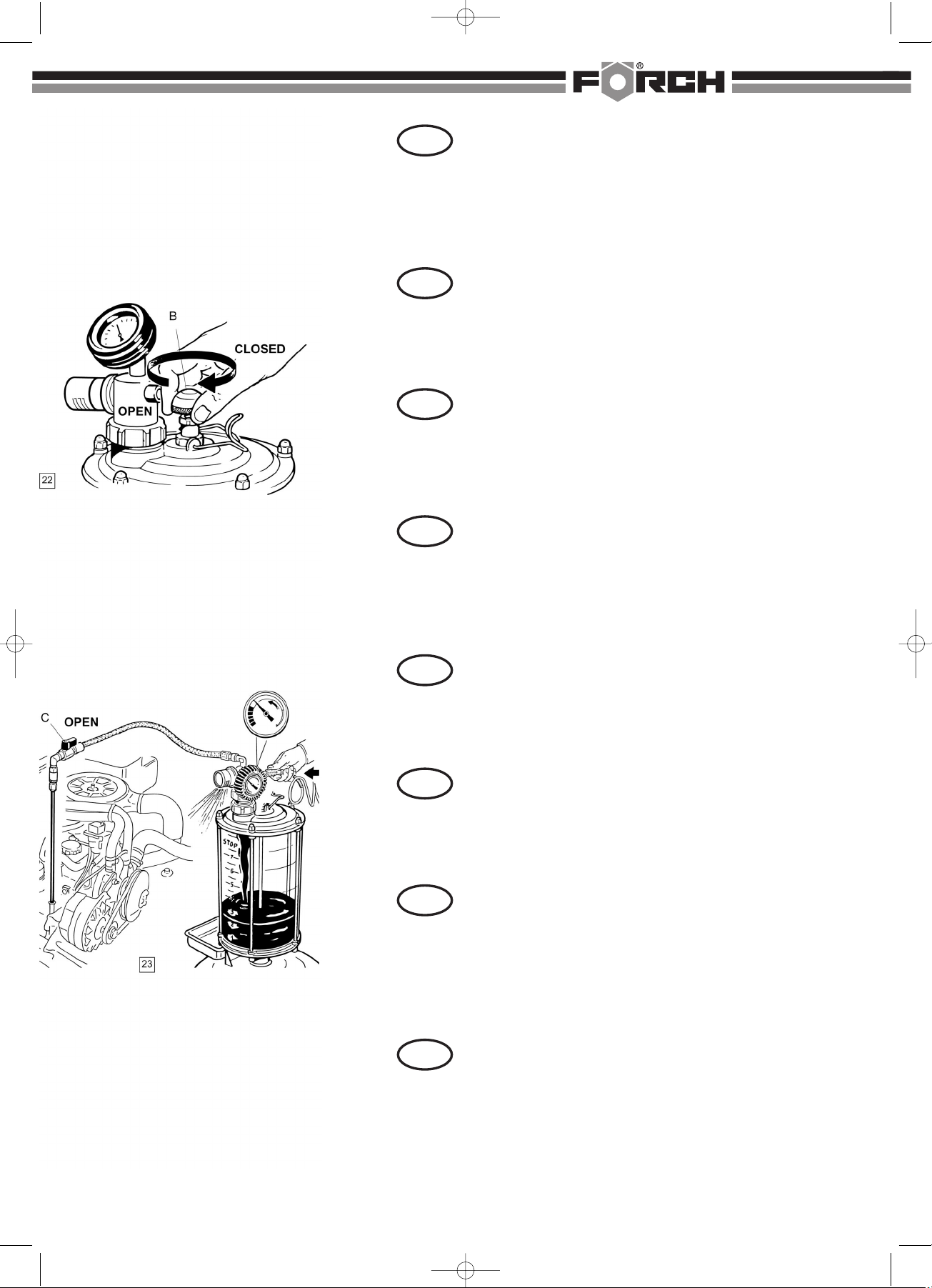
1- Wird nach Aktivierung (siehe Seite 10) das Ventil B(Abb. 22) geschlossen, wird
das Öl nur unter Verwendung der Absaugkapazität der Vorkammer abgesaugt. Auf
diese Weise können ca. 5 Liter Öl (2/3 des Fassungsvermögens der Vorkammer)
abgesaugt werden.
Wird dann das Ventil Bgedrückt, fließt das Öl rasch in den darunter befindlichen Tank, während
gleichzeitig in der Vorkammer Vakuum für einen weiteren Absaugvorgang erzeugt wird.
2- Es ist auch möglich, das heiße Altöl mit ständig angekuppelter Luftleitung abzusaugen (Abb. 23).
ACHTUNG!!! Vor Ablassen des in der Vorkammer gesammelten Öls in den Tank muß das Ventil
BAbb. 22 offen sein.
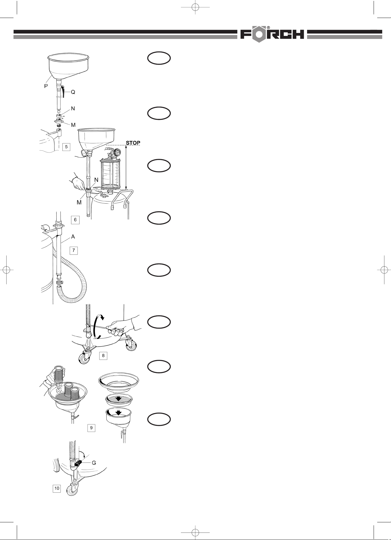
ACHTUNG!!! Füllen Sie die Vorkammer keinesfalls über die auf der Skala angegebene
STOP-Marke hinaus auf.
GER
L'olio esausto caldo può essere aspirato anche nei seguenti modi:
1- Se dopo attivazione (vedi pag. 10) chiudiamo la valvola B(fig. 22) si aspirerà
l'olio utilizzando solo la capacità di aspirazione della precamera.(È possibile
in questo modo aspirare circa 5 litri d'olio (2/3 della capacità della precamera).
Premendo poi la valvola B, l'olio verrà rapidamente scaricato nel serbatoio sottostante e contem-
poraneamente la precamera si depressurizzerà per un altra aspirazione d'olio.
2- È possibile anche aspirare l'olio esausto caldo, tenendo sempre l'aria collegata all'apparec-
chio (fig. 23).
Attenzione!!! Prima di scaricare l'olio recuperato dalla precamera dentro al serbatoio la valvola
B fig. 22 deve essere aperta.
ATTENZIONE!!! Non riempire mai la precamera oltre lo STOP indicato sulla scala graduata.
L'huile chaude peut être aspirée aussi dans les façons suivantes:
1 - Si après activation de l'appareil (voir page 10) nous fermons la valve B(fig. 22),
on pourra aspirer l'huile en utilisant seulement la capacité d'aspi-ration de la
préchambre.
Il est ainsi possible d'aspirer environ 5 litres (2/3 de la capacité de la préchambre). En appuyant
ensuite sur la valve B, I'huile sera rapidement déchargée dans le réservoir et en même temps la
préchambre se dépressurisera pour une nouvelle aspiration.
2- Il est possible aussi d'aspirer l'huile en gardant l'air connectée à l'appareil en continu (fig. 23).
ATTENTION!!! Avant de décharger l'huile récupérée de la préchambre au réservoir, la valve B
doit être ouverte (fig. 22).
ATTENTION!!! Il ne faut jamais remplir la préchambre au delà du STOP indiqué sur l'étiquette.
Udstyret kan bruges på to måder:
1- Efter aktivering (se s. 10) lukkes ventil B(fig. 22). Olien opsuges herefter udeluk-
kende ved hjælp af kammerets opsugningskapacitet. Det er på denne måde muligt
at opsuge ca. 5 liter olie. (2/3 af kammerets kapacitet).
Ved herefter at trykke på ventilen B, tømmes olien hurtigt i beholderen, der er anbragt
nedenunder. Samtidig tømmes kammeret for tryk, således at en ny opsugning af olie er mulig.
2- Det er endvidere muligt at udsuge varm olie. Dette forudsætter dog, at apparatet fortsat er
tilsluttet trykluft (fig. 23).
ADVARSEL! Inden tømning af olien fra kammeret til beholderen skal ventil Bfig. 22 åbnes.
ADVARSEL! Kammeret må aldrig fyldes til mere end STOP mærket, der er angivet på skiltet.
Gorący olej może zostać odessany także w następujący sposób.
1 Gdy po aktywacji (patrz str. 10) zostanie zamknięty wentyl B(ryc. 22), olej
zostanie odessany tylko dzięki wykorzystaniu zdolności odsysania komory
przedniej. W ten sposób można odessać ok. 5 l oleju (2/3 pojemności użytkowej komory
przedniej).
Gdy następnie zostanie naciśnięty wentyl B, olej zaczyna spływać szybko do umieszczonego
poniżej zbiornika, podczas gdy jednocześnie w komorze przedniej wytwarza się podciśnienie
dla kolejnej operacji odsysania.
2 Możliwe jest także odsysanie zużytego oleju poprzez zastosowanie stale podłączonego
przewodu powietrznego (ryc. 23)
UWAGA!!! Przed wpuszczeniem do zbiornika zgromadzonego w komorze przedniej oleju
należy otworzyć wentyl BRyc. 22.
UWAGA!!! Nie należy w żadnym przypadku napełniać komory przedniej ponad podane na skali
oznaczenie STOP.
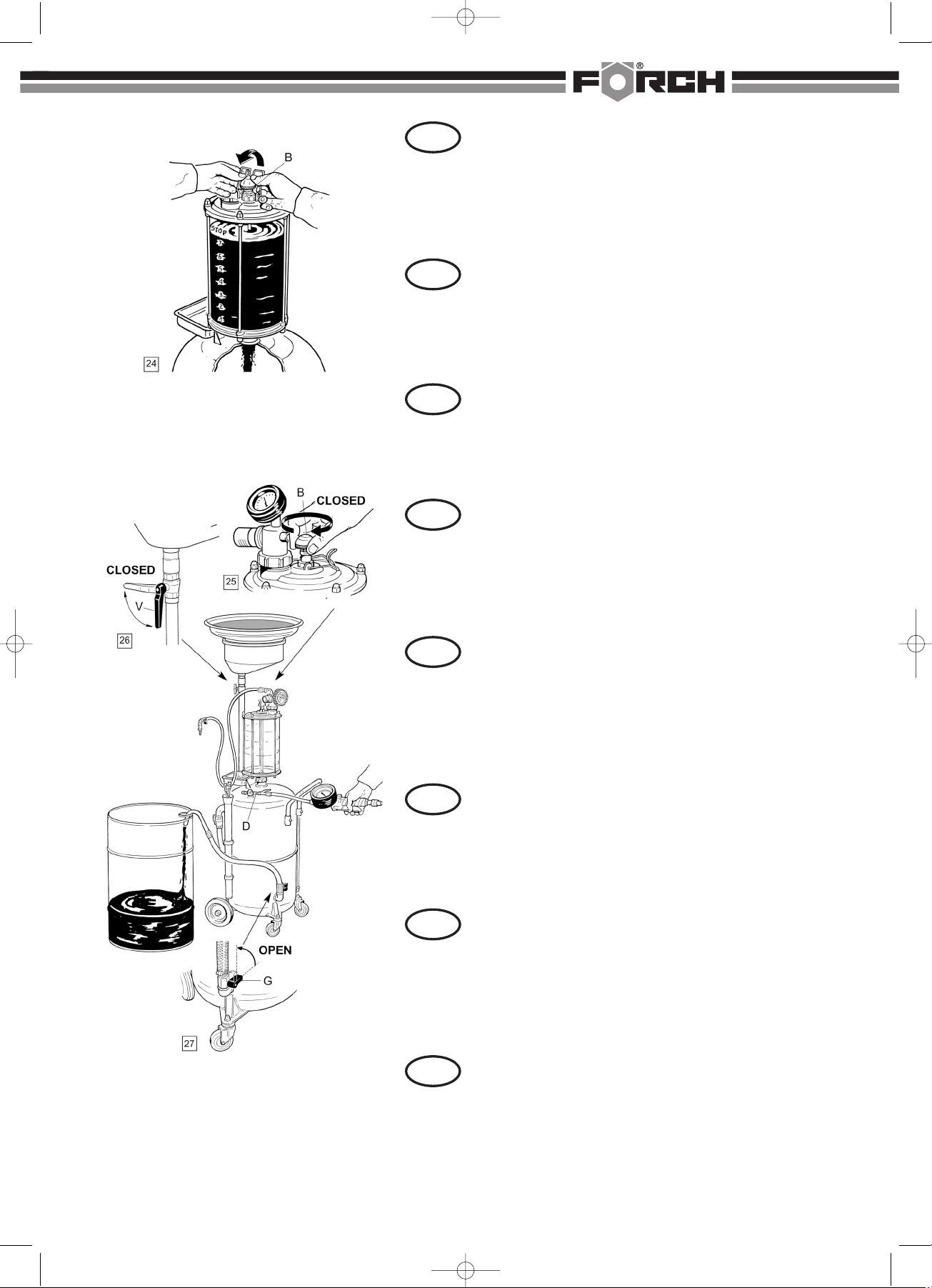
There are two ways of using the equipment:
1- After activation (see pag. 10) close valve B(fig. 22), oil will be sucked by using
only the vacuum of the trasparent reservoir.In this way it is possible to suck about 5
quarts (2/3 of the transparent chamber capacity).
Pressing on valve Bthe oil is immediately drained into the main reservoir and in the mean
time, the vacuum coming in from the reservoir, will make the transparent chamber ready for
another operation.
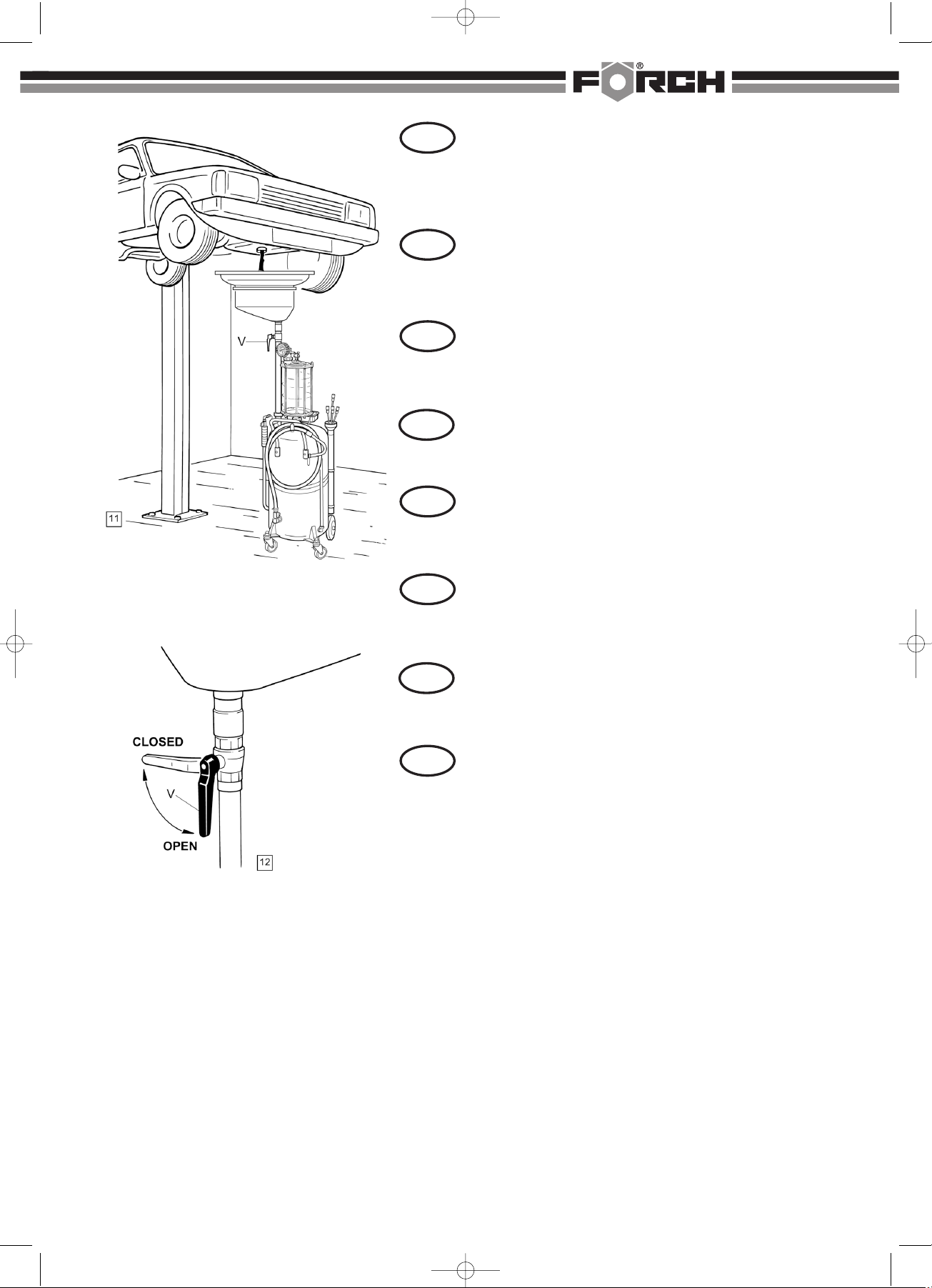
2- lt's also possible to suck oil keeping the air hooked up to the device (fig. 23). In this case,
before draining the oil from the transparent reservoir into the main reservoir, valve B must be
open (fig. 22). (Turn it counter clockwise.)
CAUTION: Do not fill the transparent reservoir over the "STOP" mark!
ITA
FRE
DAN
POL
ENG
047/GP/BJ/JK 13
Horký starý olej je možné odsávat rovněž tímto způsobem:
1- Jestliže po aktivaci (viz strana 10) zavřete ventil B(Obr. 22), olej se odsává pouze
za využití odsávací kapacity předkomory. Tímto způsobem můžete odsát cca 5 litrů
oleje (2/3 objemu předkomory).
Pokud pak na ventil Bzatlačíte, steče olej rychle do nádrže, zatímco se zároveň vytvoří v předko-
moře vakuum pro další odsávání.
2- Je rovněž možné odsávat starý horký olej při stále připojeném vedení vzduchu (Obr. 23).
POZOR!!! Před vypuštěním oleje nahromaděného v předkomoře do nádrže musí být ventil B
(Obr. 22) otevřený.
POZOR!!! Nenaplňujte předkomoru nikdy nad značku STOP uvedenou na stupnici.
CZE
También se puede aspirar el aceite caliente de la forma siguiente:
1 - Si se cierra la válvula B (imagen 22) después de la activación (véase página 10)
sólo se aspira el aceite utilizando la capacidad de aspiración de la precámara. De
esa manera se puede aspirar unos 5 litros de aceite (2/3 de la capacidad de la pre-
cámara). Si a continuación se pulsa la válvula Bentonces el aceite llega rápidamente al tanque, y
al mismo tiempo se genera un vacío en la précamara que se puede utilizar para un nuevo proceso
de aspiración.
2- También es posible aspirar el aceite usado sin la necesidad de desconectar el equipo de aire
comprimido (imagen 23).
¡ATENCIÓN! Antes de dejar salir al tanque el aceite recogido en la precámara debe abrirse la
válvula B (imagen 22).
¡ATENCIÓN! El nivel de líquido en la precámara nunca debe superar la marca STOP indicada en
la escala.
SPA
5375 9_ Bedienan. Alt lAbsaugSammelgr t:Bedienan. Alt lAbsaugSammelgr t 53759.qxd 18.04.2007 14:10 Seite 12

ACHTUNG!!! Der Tank darf niemals über den vom Ölstandanzeiger vorgegebenen
Grenzwert hinaus gefüllt werden. Um das Öl von der Vorkammer in den Tank abzulas-
sen, ist es ausreichend, das Ventil Bzu drücken und über die hierfür vorgesehene
mechanische Vorrichtung in dieser Position zu halten. Das Öl sollte noch warm sein, wenn es von der
Vorkammer in den Tank abgelassen wird.
ENTLEEREN DES TANKS
Abb. 25 - WICHTIG! Vor allem muß sichergestellt werden, daß das Ventil Bvon seiner
Blockiervorrichtung losgehakt und geschlossen ist (im Uhrzeigersinn gedreht).
Abb.26 - Das Ventil Vschließen.
Abb. 27 - Den Ablaßhahn G öffnen. An den Lufthahn DDruckluft von max. 0,5 Bar / 7 psi
anschließen, bis das ganze Öl vollständig entleert wurde.
Das Gerät ist mit einem auf 1 Bar geeichten Sicherheitsventil ausgestattet.
GER
Attenzione!!! Non riempire mai il serbatoio oltre il limite indicato dall'indicatore di
livello. Per scaricare l'olio dalla precamera dentro al serbatoio, basta premere
la valvola Btenendola in quella posizione tramite il dispositivo meccanico previsto a
questo scopo. È bene scaricare l'olio della precamera dentro al serbatoio, quando è ancora caldo.
SVUOTAMENTO DEL SERBATOIO
Fig. 25 - IMPORTANTE!!! Assicurarsi innanzitutto che la valvola B sia sganciata dal suo dispositivo
di bloccaggio e sia chiusa (girata in senso orario)
Fig. 26 - Chiudere la valvola V
Fig. 27 - Aprire il rubinetto di scarico G. Collegare al rubinetto aria Daria compressa a max.
0,5 Bar/7 psi fino a quando tutto l'olio è stato svuotato completamente.
L'apparecchio è dotato di una valvola di sicurezza tarata ad 1 bar.
ATTENTION!! Il ne faut jamais remplir le réservoir au delà de la limite indiqué par la
jauge du réservoir.
Pour faire descendre l'huile de la préchambre transparente au réservoir de
l'appareil, il suffit d'appuyer sur la valve B, et de la garder dans cette position au moyen du dispositif
mécanique prévu.
Décharger l'huile de la préchambre au réservoir quand elle est encore chaude.
VIDANGE
Fig. 25 - IMPORTANT!!! S'assurer que la valve B soit débranchée du réservoir et qu'elle soit fermée
(tourner la poignée dans le sens des aiguilles d'une montre).
Fig. 26 - Fermer la valve V.
Fig. 27 - Ouvrir le robinet de décharge G.
Brancher l'air au raccord Dde l'appareil - pression 0,5 bar -jusqu'à la vidange complète du réservoir.
La soupape de sécurité est calibrée à 1 bar.
ADVARSEL! Fyld aldrig beholderen over mængden, der angives af niveaumåleren.
Olien tømmes fra kammeret til beholderen ved at trykke på ventil B, der holdes i denne
position ved hjælp af en mekanisk anordning.
Det anbefales at tømme olien fra kammeret bag beholderen, mens olien stadig er varm.
TØMNING AF BEHOLDEREN
Fig. 25 - VIGTIGT
Kontrollér, at ventil Ber frakoblet fra blokeringsanordningen, samt at den er lukket (drejet med uret).
Fig. 26 - Luk ventilen V.
Fig. 27 - Åben tømningshanen G. Tilfør hanen Dluft ved et tryk på max. 0,5 bar/ 7 psi, indtil al
olien er opsuget. Apparatet er udstyret med en sikkerhedsventil, der er kalibreret ved 1 bar.
UWAGA!!! Nie należy nigdy napełniać zbiornika do poziomu powyżej wartości
granicznej podanej na wskaźniku stanu oleju. W celu wypuszczenia oleju z komory
przedniej do zbiornika wystarczy nacisnąć wentyl Bi utrzymywać w tej pozycji za
pomocą przeznaczonego do tego celu urządzenia mechanicznego. Podczas spuszczania z komory
przedniej do zbiornika olej powinien być jeszcze ciepły.
OPRÓŻNIANIE ZBIORNIKA
Ryc. 25 WAŻNE! Przede wszystkim należy dopilnować, aby wentyl B został odhaczony od
urządzenia blokującego go i zamknięty (obrócony w kierunku zgodnym z kierunkiem ruchu wskazó-
wek zegara).
Ryc. 26 Zamknąć wentyl V.
Ryc. 27 Odkręcić kurek spustowy G. Podłączyć do kurka Dsprężone powietrze o max 0,5 bar/ 7
psi az do momentu całkowitego spuszczenia oleju.
Urządzenie jest wyposażone w wentyl bezpieczeństwa skalibrowany na 1 bar.
WARNING! Never fill the unit's storage tank over the max. level indicated by the gauge.
To transfer fluids from the transparent chamber to the unit's reservoir tank press down
on valve Band secure it with the metal lock provided.
Always do this operation when the oil is hot.
EMPTYING THE RESERVOIR
Fig. 25 - Make sure that valve Bis in its upper position and closed by turning it clockwise. (If the
storage tank is pressurized when valve B is open it could damage the unit's transparent chamber.)
Fig. 26 - Close the ball valve V.
Fig. 27 - Open the ball valve G.
Connect shop air (7 psi -0,5 bar) to valve Duntil all fluids have been transferred from the unit's
storage tank. The unit storage tank has been equipped with a pneumatic safety valve calibrated
at 14 PSl - 1 Bar.
ITA
FRE
DAN
POL
ENG
047/GP/BJ/JK 14
POZOR!!! Nádrž se nesmí nikdy naplnit nad mezní hodnotu uvedenou na ukazateli stavu
oleje. Pro vypuštění oleje z předkomory do nádrže postačuje zatlačit na ventil Ba pomocí
příslušného aretačního mechanizmu jej udržet v této poloze. Když se olej vypouští z
předkomory do nádrže, měl by být ještě teplý.
VYPRÁZDNĚNÍ NÁDRŽE
Obr. 25 - DŮLEŽITÉ! Především je třeba se ujistit, zda je ventil Buvolněný z aretace a zavřený
(otočený ve směru hodinových ručiček).
Obr. 26 - Zavřete ventil V.
Obr. 27 - Otevřete vypouštěcí kohout G. K ventilu Dpřipojte přívod stlačeného vzduchu (max. 0,5 bar /
7 psí) - až do úplného vypuštění veškerého oleje.
Zařízení je vybaveno bezpečnostním ventilem kalibrovaným na 1 bar.
GER
¡ATENCIÓN!
La cantidad de aceite recogido nunca debe superar el límite señalado en el indicador de
nivel de aceite. Para dejar salir el aceite que se encuentra en la precámara al tanque
sólo debe pulsarse la válvula B. Mantener la presión a la válvula utilizando el cierre suministrado. El
aceite debería estar caliente al llegar de la precámara al tanque.
VACIAR EL TANQUE
Imagen 25 - ¡IMPORTANTE! Debe asegurarse de que el cierre de la vávula B esté abierta y que la
misma esté cerrada (girar en el sentido del las agujas del reloj).
Imagen 26 - Cerrar la válvula V.
Imagen 27 - Abrir el grifo G. Conectar una manguera de aire comprimido de 0,5 bar / 7 psi a la toma
D. Vaciar todo el tanque. El aparato dispone de una válvula de seguridad calibrada a 1 bar.
SPA
5375 9_ Bedienan. Alt lAbsaugSammelgr t:Bedienan. Alt lAbsaugSammelgr t 53759.qxd 18.04.2007 14:10 Seite 13

ES KANN VORKOMMEN, DASS ANGESAUGTES ÖL AM SCHALLDÄMPFER
AUSTRITT. DIES ERFOLGT IMMER DANN, WENN:
Abb. 28 - Öl angesaugt wird und dabei die Druckluft ständig am Gerät angeschlossen ist
und die Vorkammer über den angegebenen Höchststand hinaus gefüllt ist.
Abb. 29 - die transparente Vorkammer in den Tank entleert wird, ohne daß vorher das Ventil B
geöffnet (gegen den Uhrzeigersinn gedreht) wurde. Dieser Vorgang ist nur dann nicht erforderlich,
wenn der Tank sich noch in Unterdruck befindet.
GER
PUO CAPITARE CHE L'OLIO ASPIRATO ESCA DAL SILENZIATORE. CIÒ ACCADE
SEMPRE:
Fig. 28 - Quando si aspira l'olio tenendo l'aria collegata in continuo all'apparecchio e la
precamera è piena oltre il livello indicato.
Fig. 29 - Quando la precamera trasparente viene svuotata dentro al serbatoio, senza aver prima
aperto (girata in senso antiorario) la valvola B. Questa operazione non è necessaria solo quando il
serbatoio è ancora in depressione.
IL SE PEUT QUE L'HUILE ASPIREE SORTE DU SlLENCIEUX. CELA SE VERIFIE
TOUJOURS:
Fig. 28 - Quand on aspire l'huile avec l'air branché en continu à l'appareil et qu'on
remplit jusqu'au bout la cuve transparente sans respecter la limite STOP indiquée sur la cuve.
Fig. 29 - Quand on fait la vidange de la préchambre transparente sans avoir ouvert (tournée dans le
sens contraire des aiguilles d'une montre) la valve B. Il n'est pas nécessaire d'ouvrir la valve B
seulement quand le réservoir est dépres-surisé (sous vide).
DET KAN FOREKOMME, AT DER KOMMER OLIE UD AF LYDDÆMPEREN.
ÅRSAGEN KAN VÆRE:
Fig. 28 - Hvis man suger olie op, mens trykluften er koblet til udstyret, og kammeret
bliver overfyldt.
Fig. 29 - Hvis det gennemsigtige kammer tømmes i beholderen uden forudgående åbning af ventil B
(drejes mod uret). Det er ikke nødvendigt at åbne ventil B, hvis beholderen stadig er under tryk.
MOŻE SIĘ ZDARZYĆ, ZE ZASSANY OLEJ BĘDZIE PRZECIEKAŁ NA TŁUMIKU, MA
TO MIEJSCE WTEDY, GDY:
Ryc. 28 Olej jest zasysany a sprężone powietrze jest ciągle jeszcze podłączone do
urządzenia i komora przednia jest wypełniona powyżej podanego stanu maksymalnego.
Ryc. 29 przezroczysta komora przednia w zbiorniku jest opróżniania mimo, że wentyl Bnie został
przedtem otwarty (przekręcony w kierunku przeciwnym do ruchu wskazówek zegara). Operacja ta
nie jest konieczna tylko wtedy, gdy w zbiorniku występuje podciśnienie.
SOMETIMES THE SUCKED OIL MAY LEAK OUT OF THE MUFFLER.
THIS ALWAYS HAPPENS WHEN:
Fig. 28 - Oil is sucked keeping air continuously connected to the equipment and the
transparent chamber is filled over the STOP mark.
Fig. 29 - Oil is discharged from the transparent chamber into the lower reservoir without opening
valve B. It is not necessary to open valve Bonly when the lower reservoir is depressurized (when
there is a vacuum).
ITA
FRE
DAN
POL
ENG
047/GP/BJ/JK 15
MŮŽE SE STÁT, ŽE ODSÁVANÝ OLEJ UNIKÁ V MÍSTĚ TLUMIČE HLUKU. TO SE
DĚJE VŽDY TEHDY, KDYŽ:
Obr. 28 - je olej odsáván a přitom je k zařízení stále připojen přívod stlačeného vzduchu
a předkomora je naplněna nad uvedenou maximální hodnotu.
Obr. 29 - se průhledná předkomora vyprazdňuje do nádrže, aniž by se předtím otevřel ventil B
(otáčením proti směru hodinových ručiček). Otevření ventilu B není nutné pouze tehdy, když je v nádrži
ještě podtlak.
CZE
ES POSIBLE QUE SALGA AIRE ASPIRADO POR EL SILENCIADOR. ESO PASA
SIEMPRE EN LOS SIGUIENTES CASOS:
Imagen 28 - Cuando se aspira aceite y el aparato está conectado permanentemente al
aceite comprimido y el nivel de líquido en la precámara ya ha superado el nivel máximo.
Imagen 29 - Cuando se deja salir el contenido de la precámara transparente al tanque sin haberse
abierto anteriormente la válvula B(en sentido contrario a la agujas del reloj). Sólo se puede omitir ese
proceso en caso de que en el tanque haya una depresión.
SPA
5375 9_ Bedienan. Alt lAbsaugSammelgr t:Bedienan. Alt lAbsaugSammelgr t 53759.qxd 18.04.2007 14:10 Seite 14

Abb. 30 - das Gerät mit voller Vorkammer / vollem Tank bewegt wird und die Bewegung des
Öls das Venturi-Aggregat verschmutzt.
Abb. 31 - In diesem Fall wird wie folgt vorgegangen:
- Nehmen Sie den Schalldämpfer heraus, zerlegen Sie ihn und reinigen Sie alle seine Bestandteile.
- Die Druckluft an die Schnellverbindung anschließen und
Abb.32 - die Druckluft, während man einen Lappen in der angegebenen Weise hält, an das Gerät
anschließen, bis das in das Venturi-Aggregat eingetretene Öl vollständig herausgeblasen wurde.
- Den Schalldämpfer wieder montieren.
GER
Fig. 30 - Quando l'apparecchio viene spostato con precamera e serbatoio pieno ed il movi-
mento dell'olio sporca il gruppo Venturi.
Fig. 31 - In questo caso agire nel modo seguente:
- togliere il silenziatore, smontarlo e pulirne tutti i componenti
- collegare l'aria compressa all'attacco rapido e
Fig. 32 - tenendo uno straccio come indicato, collegare aria compressa all'apparecchio fino a quando tutto
l'olio entrato nel gruppo Venturi è uscito.
- rimontare il silenziatore.
Fig. 30 - Quand on déplace l'appareil avec la cuve transparente pleine et que l'huile en
s'agitant salit le groupe Venturi. (Il est important de faire la vidange de la cuve transparente
dans le réservoir quand l'huile est encore chaude et avant de déplacer l'appareil.)
Fig. 31 - Dans ce cas agir de la façon suivante:
- dévisser le silencieux, le démonter et le nettoyer soigneusement
- brancher l'air au raccord rapide et:
Fig. 32 - brancher l'air à l'appareil en tenant un chiffon comme indiqué et faire sortir toute l'huile entrée
dans le groupe Venturi.
- Remonter le silencieux.
Fig. 30 - Hvis udstyret flyttes, mens kammer-beholder er fyldt. Oliesprøjt kan tilsmudse Venturi
enheden.
DER KAN GØRES FØLGENDE:
Fig. 31 - I dette tilfælde benyttes følgende fremgangsmåde:
- Fjern lyddæmperen, adskil den, og rengør alle komponenter.
- Slut trykluft til lynkoblingen, og
Fig. 32 - Hold en klud som vist på tegningen, tilkobl trykluft indtil al olien er fjernet fra Venturi enheden.
- Montér lyddæmperen på ny.
Ryc. 30 Urządzenie z pełną komorą przednią/ pełnym zbiornikiem jest poruszane i ruch
oleju powoduje zabrudzenie agregatu Venturi.
Ryc. 31 W tym przypadku należy postępować następująco:
Należy wyjąć tłumik, rozebrać go i oczyścić wszystkie części składowe
Podłączyć sprężone powietrze do złączki i
Ryc. 32 podłączyć sprężone powietrze do urządzenia trzymając w podany sposób szmatkę, tak długo
aż olej, który dostał się do agregatu Venturi zostanie całkowicie wydmuchany.
Ponownie zamontować tłumik.
Fig.30 - The equipment is moved and the transparent chamber is full of oil. Oil splashes can
dirty the Venturi group.
(Oil must always be discharged from the transparent chamber into the reservoir when the oil is
hot and before moving the equipment.)
Fig. 31 - In these cases proceed as follows:
- remove the muffler, dismantle it and clean all the components.
Fig. 32 - hold a rag as indicated, connect the compressed air to the device until all the oil comes out of the
Venturi group.
- Reassemble and mount the muffler again.
ITA
FRE
DAN
POL
ENG
047/GP/BJ/JK 16
Obr. 30 - se zařízení přemísťuje s plnou předkomorou / plnou nádrží a pohyb oleje znečistí
Venturiho trubici.
Obr. 31 - V takovém případě postupujte následovně:
- Demontujte tlumič hluku, rozeberte ho a vyčistěte všechny jeho součástky.
- Namontujte rychlospojku na přívod stlačeného vzduchu, a
Obr. 32 - zatímco držíte hadr uvedeným způsobem, připojte přívod stlačeného vzduchu k zařízení
- až do úplného vyfouknutí oleje, který vnikl do Venturiho trubice.
- Namontujte opět tlumič hluku.
CZE
Imagen 30 - Cuando se mueve el aparato con una precámara llena o con un tanque lleno y a
causa del movimiento el aceite ensucia el sistema Venturi.
Imagen 31 - En este caso debe hacerse lo siguiente:
- Debe quitarse y desmontarse el silenciador. Limpiar todos sus componentes.
- Conectar el aire comprimido al conector rápido y
Imagen 32 - soplar aire en el sistema Venturi hasta que salga todo el aceite mientras sujeta un trapo de la
manera indicada.
- Montar el silenciador.
SPA
5375 9_ Bedienan. Alt lAbsaugSammelgr t:Bedienan. Alt lAbsaugSammelgr t 53759.qxd 18.04.2007 14:10 Seite 15
Table of contents
Other Forch Service Equipment manuals