manuals.online logo
Brands
  1. Home
  2. •
  3. Brands
  4. •
  5. Fortin
  6. •
  7. Automobile Accessories
  8. •
  9. Fortin EVO ALL User manual

Fortin EVO ALL User manual

ADDENDUM - SUGGESTED WIRING CONFIGURATION
ADDENDA - SCHÉMA DE BRANCHEMENT SUGGÉRÉ
ALL REV.: 20170605
FLASH LINK UPDATER 2 FLASH LINK UPDATER 2
1X
Microsoft Windows Computer &
Internet connection
Ordinateur Microsoft Windows &
connection Internet
FLASH LINK UPDATER 2 FLASH LINK UPDATER 2
1X
Microsoft Windows Computer &
Internet connection
Ordinateur Microsoft Windows &
connection Internet
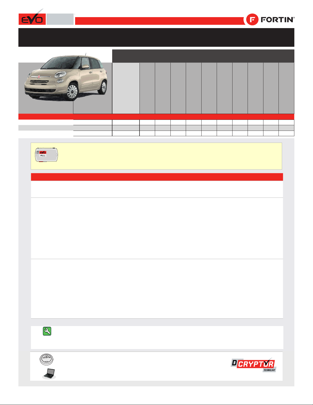
Vehicle functions supported in this diagram (functional if equipped) | Fonctions du véhicule sup-
portées dans ce diagramme (fonctionnelles si équipé)
VEHICLE
VEHICULES
YEARS
ANNÉES
Immobilizer bypass
Contournement
d’immobilisateur
Lock
Unlock
Tachometer
Trunk - open
Door Status
Trunk Status
Hood Status
*
Hand-Brake Status
Foot-Brake Status
OEM Remote monitoring
FIAT
500
2012-2016
•
•
•
•
•
•
•
•
•
•
•
500 Turbo
2012-2016
•
•
•
•
•
•
•
•
•
•
•
500C
2012-2016
•
•
•
•
•
•
•
•
•
•
•
Parts required (Not included) Pièce(s) requise(s) (Non incluse(s))
1x Fuse 1x 10 Amp Fusible
HARDWARE VERSION
VERSION MATÉRIELLE FIRMWARE VERSION
VERSION LOGICIELLE This manual may change without notice.
www.fortinbypass.com for latest version.
Ce Guide peut faire l’objet de changement
sans préavis. www.fortinbypass.com pour la
récente version.
MINIMUM 6 74.[29]
CHRYSLER/DODGE/JEEP/MITSUBISHI MINIMUM
NOTES
* Hood Status Hood Status : functional if equipped with a
factory hood switch.
HOOD STATUS : fonctionnel si équipé d’un commutateur de capot
d’origine.
OPTION 1
WITH OEM ALARM FUNCTIONAL
AND OEM REMOTE FUNCTIONAL :
The vehicle’s OEM alarm can only be
disarmed through the OEM remote.
When the vehicle is remote started, if the
remote starters remote is used to unlock the
doors, the engine will shut off as soon as a
door is opened and the vehicle will have to
be started normally with the key, the alarm
will be disabled.
AVEC ALARME D’ORIGINE FONCTIONNELLE
ET TÉLÉCOMMANDE D’ORIGINE FONCTIONNELLE :
La désactivation de l’alarme du véhicule par déverrouillage des portes
est possible qu’avec la télécommande d’origine.
Au démarrage à distance, si la télécommande du démarreur à distance
est utilisée pour déverrouiller les portes, à l’ouverture d’une porte le
moteur s’éteint et il faut tourner la clé de contact pour redémarrer le
véhicule, l’alarme sera ainsi désactivée.
OPTION 2
WITH OEM ALARM NOT FUNCTIONAL
AND OEM REMOTE NOT FUNCTIONAL :
The vehicle’s OEM alarm can only be
disarmed through the OEM remote.
Remove the battery from the vehicle OEM
remote to cancel the vehicle OEM alarm
system’s and protect the vehicle with the
integreted alarm system’s of the EVO-ALL.
AVEC ALARME D’ORIGINE NON FONCTIONNELLE
ET TÉLÉCOMMANDE D’ORIGINE NON FONCTIONNELLE :
La désactivation de l’alarme du véhicule par déverrouillage des portes
est possible qu’avec la télécommande d’origine.
Retirez la batterie de la télécommande d’origine pour annuler le
système d’alarme d’origine du véhicule et protéger le véhicule par le
système d’alarme intégré du EVO-ALL.
Guide # 63381
Page 1 / 8
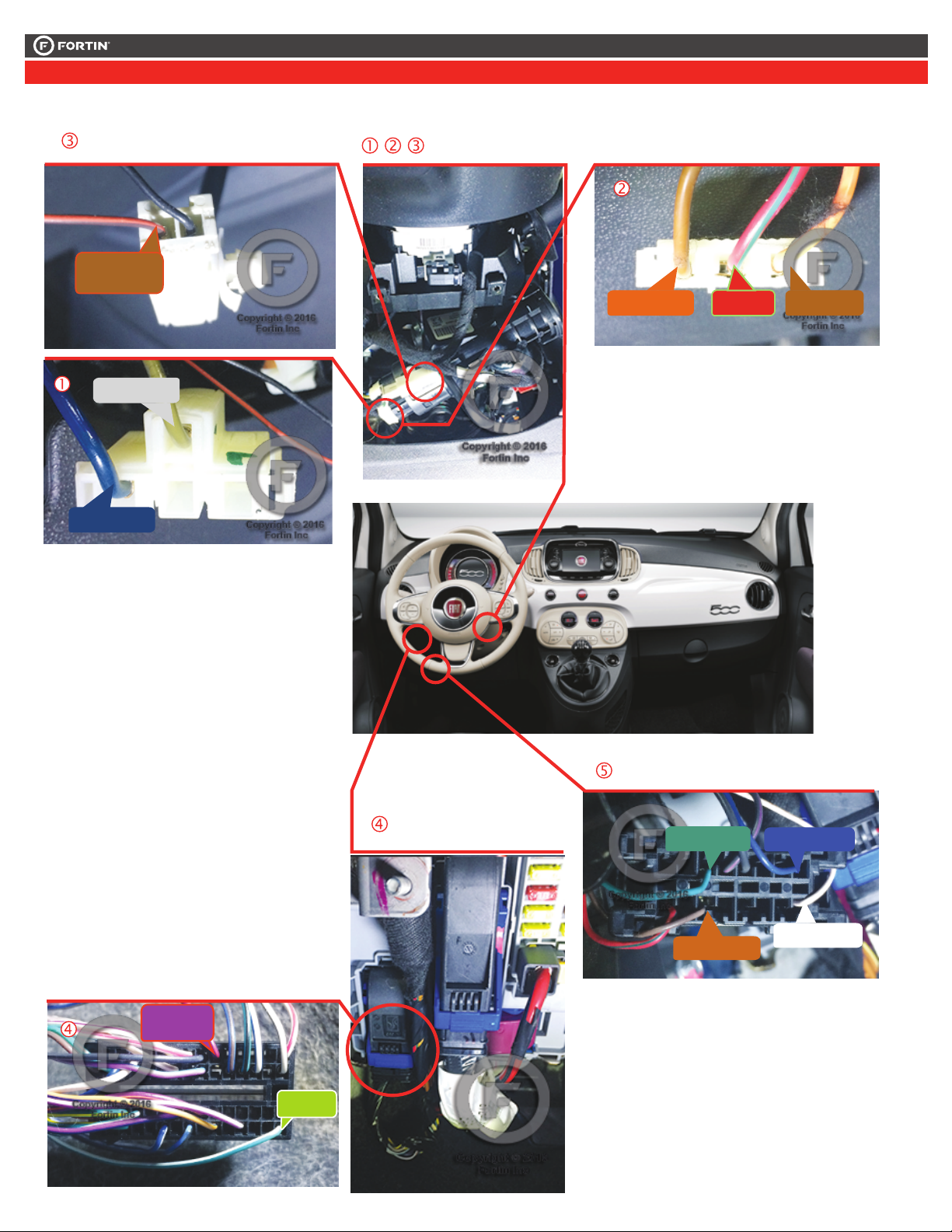
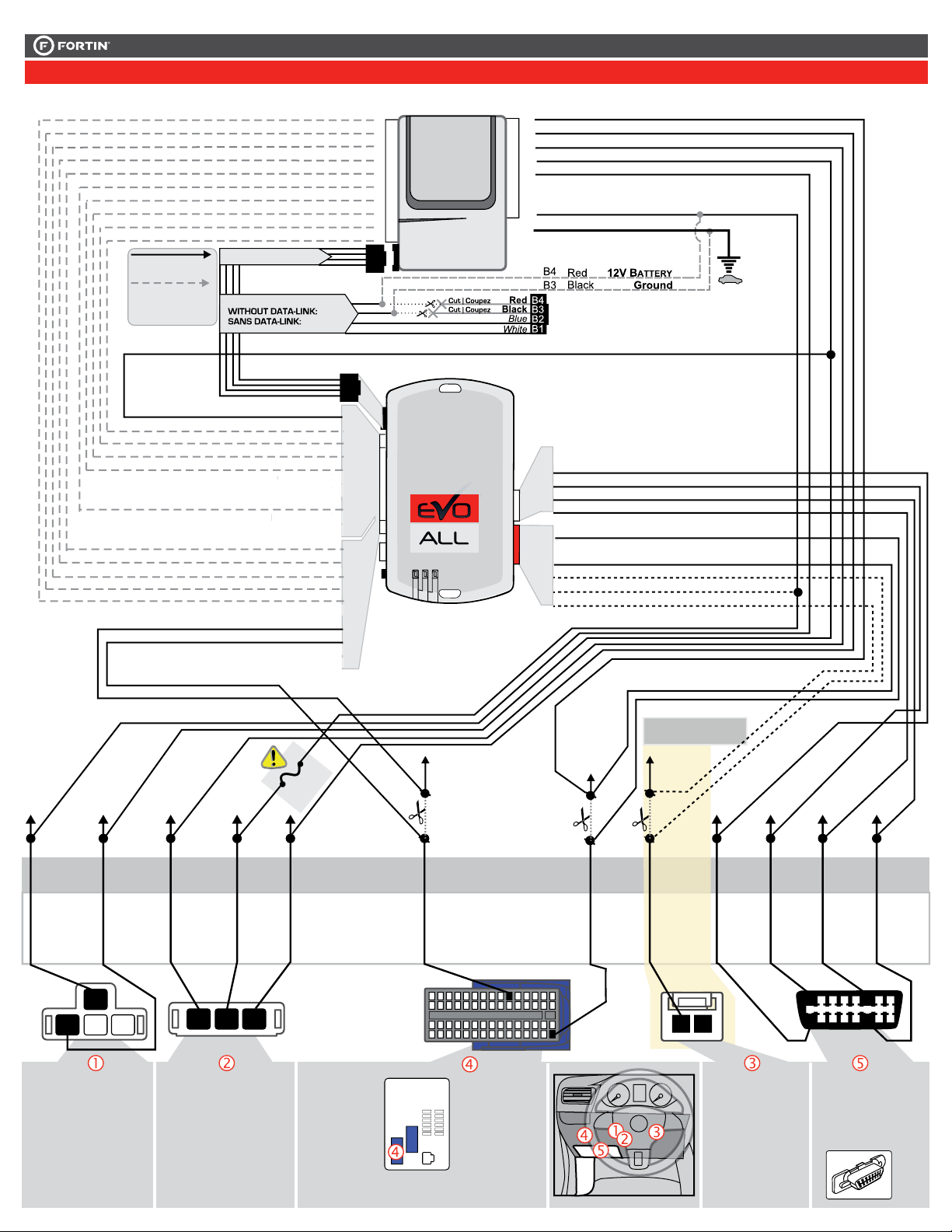
REGULAR INSTALLATION
INSTALLATION RÉGULIÈRE
This guide may change without notice. See www.fortin.ca for latest version.
Ce guide peut faire l’objet de changement sans préavis. Voir www.fortin.ca pour la récente version.
NOTES
Program bypass option
IF OEM FUNCTIONAL:
Programmez l’option du contournement
SI TÉLÉCOMMANDE D’ORIGINE
FONCTIONNELLE:
UNIT OPTION
OPTION UNITE DESCRIPTION
A6 OFF
NON
OPTION 1 : With OEM
remote functional
OPTION 1 : Avec télécom-
mande d’origine fonction-
nelle
Program bypass option:
Programmez l’option du contournement:
UNIT OPTION
OPTION UNITE DESCRIPTION
C1
OEM Remote status (Lock/Unlock)
monitoring
Suivi des status (Verrouillage/Déverrouil-
lage) de la télécommande d’origine
OPTION 1
Program bypass option
IF OEM FUNCTIONAL:
Programmez l’option du contournement
SI TÉLÉCOMMANDE D’ORIGINE
FONCTIONNELLE:
UNIT OPTION
OPTION UNITE DESCRIPTION
A5 OFF
NON
OPTION 1 : With OEM
remote functional
OPTION 1 : Avec télécom-
mande d’origine fonction-
nelle
Page 2 / 8
This guide may change without notice. See www.fortin.ca for latest version.
Ce guide peut faire l’objet de changement sans préavis. Voir www.fortin.ca pour la récente version.
DESCRIPTION | DESCRIPTION
(~)CAN2 LOW
(~)CAN2 HIGH
(~)CAN1 LOW
OBD-II connector
Connecteur OBD-II
(+)12V (+)STARTER
Key cylinder.
Cylindre de la clé.
(+)IGNITION2
(+)ACCESORY
(+)IGNITION1
Ignition switch.
Commutateur d’ignition.
Dash board, BCM.
Tableau de bord, BCM.
(MUX)DOOR
LOCKS
(~)CAN1 HIGH
(+)KEY
RELEASE
(-)HORN
Page 3 / 8
This guide may change without notice. See www.fortin.ca for latest version.
Ce guide peut faire l’objet de changement sans préavis. Voir www.fortin.ca pour la récente version.
 In A1
 In A2
 In A3
 Out A4
 Out A5
 In A6
 In A7
 In A8
 In A9
 A10
 Out A11
 Out A12
 In A13
 Out A14
 Out A15
 A16
 A17
 A18
 A19
 A20
C5 
C4 
C3 
C2 
C1 
D6 
D5 
D4 
D3 
D2 
D1 
AC
D
WIRING CONNECTION | GUIDE DE BRANCHEMENTS
1
2
2
3
1
4
10 456789
192021 17 16
1415 13 12
18
11
27 25 24 23 2230 29 28
3134 33 32353839 37 3640414445 43 42
4649 48 47505354 52 5155565960 58 57
26
123
OBD-II
connector
Front view
Connecteur
OBD-II
Vue de face
1 2 3 4 5 67 8
9 10 11 12 13 14 15 16
6
14
1
9
Gray
Gris Dk.Blue
Bleu Foncé Dk.Blue
Bleu
Foncé
White
Blanc
Orange
Orange Red/
Lt.Green
Rouge/
Vert Pâle
Lt.Green
Vert Pâle
Violet/
Red
Mauve/
Rouge
Brown/
Orange
Brun/
Orange
Brown
Brun Brown
Brun
3
2 1
(+)ACCE-
SORY
(+)
IGNITION1
(+)
IGNITION2 (+)12V (+)
STARTER
(MUX)
DOOR
LOCKS
(+)KEY
RELEASE
OPTIONAL - IDLE MODE
OPTIONNELS
MODE CONTINUE
(~)CAN2
HIGH
(~)CAN1
HIGH
(~)CAN1
LOW (~)CAN2
LOW
Back view. 4-pin
Black connector.
at Ignition
switch.
Vue de dos.
Connecteur Noir
4-pins, au
commutateur
d’ignition.
Back view. 3-pin
Black connector.
at Ignition
switch.
Vue de dos.
Connecteur Noir
3-pins, au
commutateur
d’ignition.
Back view. 60-pin
Black and Blue
connector. at
dash board,
BCM.
Vue de dos.
Connecteur Noir
et Bleu 60-pins,
dans le tableau
de bord, BCM.
Back view. 2-pin
White connector.
at key cylinder.
Vue de dos.
Connecteur White
2-pins, au
cylindre de la
clé.
CUT
CUT
FUSIBLE
FUSIBLE
FUSIBLE
FUSIBLE
FUSIBLE
FUSIBLE
FUSIBLE
FUSIBLE
FUSIBLE
FUSIBLE
FUSIBLE
FUSIBLE
(-)HORN
Green/
White
Vert/
Blanc
CUT
1
C4D3
A1
D2
A18
A17 D1
RS7RS2/D2RS6ARS6/A1RS5 C3 C1 C2
FUSE
FUSIBLE
D6
D4
RS19 OUT Horn (-)
Horn(-)
Horn(-)
RS19
CAN 1 LOW
CAN 1 HIGH
CAN 2 LOW
CAN 2 HIGH
WITH | AVEC DATA-LINK:
ALWAYS REQUIRED
TOUJOURS REQUIS
NOT REQUIRED WITH
DATALINK
NON REQUIS EN
DATA-LINK
B
REMOTE
STARTER
DÉMARREUR
À DISTANCE
WITH | AVEC DATA-LINK:
Direct connection
Branchement directe
HOOD IN RS8
(-)
HAND BRAKE IN RS9
(-)
TRUNK RELEASE
(-) OUT RS11
(+/-) IN RS12
TACHOMETER
F
OOT
B
RAKE
(+)
IN RS13
GROUND OUT WHILE RUNNING
(-) OUT RS14
TRUNK
(-)
IN RS15
DOOR
(-) IN RS16
UNLOCK
(-) OUT RS17
LOCK
(-) OUT RS18
A15
A14
A13
A12
A11
A8
A5
A4
A3
A2
Ground | Masse
(-)
RS1
12V BATTERY
RS2 IN
(+)
PARKING LIGHTS
RS3 OUT (-)
PARKING LIGHTS
RS4 OUT (+)
ACCESSORY
RS5 OUT (+)
IGNITION
RS6 IN/OUT (+)
IGNITION2
RS6a OUT (+)
1
STARTER
RS7 OUT (+)
Key release (Vehicle)
(+)12V
Key release (connector)
(MUX) Door Lock (Connector)
(MUX)Door Lock (Vehicle)
(-) Hood Status
(-) Hand Brake
(-) Trunk Release
(-/+) Tachometer
(+) Foot Brake
(-) Ground While Running
(-) Trunk Status
(-) Door Status
(-) Unlock
(-) Lock
(+) Ignion







In

In

In
Page 4 / 8
Release the programming
button when the LED is BLUE.
2
1
3
4
5
Relâchez le bouton de
programmation quand la DEL
est BLEU.
Insert the required remaining
connectors. Insérez les connecteurs
requis restants.
LOCK
ACCO N
PUSH
START
IGN
T
ATTENDRE,
ournez la clé à Ignition.
urn the key to the
The BLUE LED will turn OFF. La DEL BLEUE s’éteindra.
The BLUE LED will flash. La DEL BLEUE clignotera.
The BLUE LED will turn OFF.
The RED LED will turn ON.
La DEL BLEU s’éteindra.
La DEL ROUGE s’allumera.
Turn the key to the
OFF position. Tournez la clé à la
position Arrêt (OFF).
T
WAIT,
Ignition ON/RUN position.
LOCK
ACCON
PUSH
START
OFF
CONTINUED NEXT PAGE | CONTINUEZ À LA PAGE SUIVANTE
x1
HOLD
Press and hold
Insert
the
programming button:
the 4-Pin (Data-Link)
connector.
Appuyez maintenir
enfoncé
Insérez
et
le bouton de
programmation:
le connecteur 4 pins
(Data-Link)
The Blue, Red, Yellow and
Blue & Red LEDs will
alternatively illuminate.
Les DELs Bleue, Rouge,
Jaune et Bleue & Rouge
s'allumeront alternativement.
RELEASE
If the LED is not solid BLUE
disconnect the 4-Pin connector
(Data-Link) and go back to step 1.
ON BLUE
BLEU
Si le DEL n'est pas BLEU
débranchez le connecteur 4
pins (Data-Link) et allez au
début de l'étape 1.
ON
OFF
IGNITION ON IGNITION OFF
WAIT
OFF
FLASH
RAPIDLY
IGNITION OFF IGNITION ON
ON
This guide may change without notice. See www.fortin.ca for latest version.
Ce guide peut faire l’objet de changement sans préavis. Voir www.fortin.ca pour la récente version.
DCRYPTOR PROGRAMMING PROCEDURE | PROCÉDURE DE PROGRAMMATION AVEC DCRYPTEUR
Parts required (not included) Pièces requises (non incluses)
1x FLASH LINK UPDATER 2,
1x FLASH LINK MANAGER software
1x Microsoft Windows Computer with
Internet connection
1x FLASH LINK UPDATER 2,
1x Programme FLASH LINK MANAGER
1x Ordinateur Microsoft Windows avec
connection Internet
Page 5 / 8
6
LOCK
ACCON
PUSH
START
IGN
LOCK
ACCON
PUSH
START
OFF
The YELLOW LED will turn ON.
The RED LED will turn OFF.
The RED LED will turn ON.
La DEL JAUNE s’allumera.
La DEL ROUGE s’éteindra.
La DEL ROUGE s’allumera.
The RED and the YELLOW
LED’s alternate.
Les DELs ROUGE et JAUNE
alternent.
LOCK
ACCO N
PUSH
START
IGN
Tournez la clé à Ignition.
urn the key to theT
Ignition ON/RUN position.
Turn the key to the OFF
position.
Turn the key to the Ignition
ON/RUN position,
UNTIL:
Repeat this process approxi-
mately 10 times.
Répétez ce processus
environ 10 fois.
Tournez la clé à la position
Arrêt (OFF).
Tournez la clé à Ignition,
JUSQU’À CE QUE:
ON
OFF
ON
x10
IGNITION ON
ON ON
ON
IGNITION OFF
ON
This guide may change without notice. See www.fortin.ca for latest version.
Ce guide peut faire l’objet de changement sans préavis. Voir www.fortin.ca pour la récente version.
KEY BYPASS PROGRAMMING PROCEDURE 2/2 | PROCÉDURE DE PROGRAMMATION CONTOURNEMENT DE CLÉ 2/2
EVO-ALL
Disconnect all the connectors and after
the Data-Link (4-pins) connector.
Débranchez tous les connecteurs et ensuite
le connecteur Data-Link (4-pins).
FLASH LINK
UPDATER 2
FLASH LINK
UPDATER 2
FLASH LINK MANAGER
SOFTWARE | PROGRAMME
Microsoft Windows
Computer with
Internet connection
Ordinateur Microsoft
Windows avec
connection Internet
Parts required (not included)
Pièces requises (non incluses)
Connect the module to the
FLASH LINK UPDATER 2
and visit the DCryptor menu
in the Flash-Link Manager.
Branchez le module au
FLASH LINK UPDATER 2
et visitez le menu DCryptor
dans le Flash-Link Manager.
AFTER DCRYPTOR PROGRAMMING COMPLETED
Go back to the vehicle and reconnect the 4-Pin (Data-Link)
connector and after, all the remaining connector.
APRÈS LA PROCÉDURE DE PROGRAMMATION
DCRYPTOR COMPLETÉE : retournez au véhicule et
rebranchez le connecteur 4-pins (Data-Link)
et après, tous les connecteurs du EVO-ALL.
EVO-ALL
7
8
9
REMOTE STARTER / ALARM VERIFICATION
PROCEDURE | PROCÉDURE DE VÉRIFICATION
DU DÉMARREUR À DISTANCE / ALARME
Test the remote starter. Remote start the vehicle.
Testez le démarreur à distance. Démarrez le véhicule
à distance.
The module is now programmed.
Le module est programmé.
REMOTE STARTER / ALARM VERIFICATION
PROCEDURE | PROCÉDURE DE VÉRIFICATION
DU DÉMARREUR À DISTANCE / ALARME
Test the remote starter. Remote start the vehicle.
Testez le démarreur à distance. Démarrez le véhicule
à distance.
The module is now programmed.
Le module est programmé.
Page 6 / 8
This guide may change without notice. See www.fortin.ca for latest version.
Ce guide peut faire l’objet de changement sans préavis. Voir www.fortin.ca pour la récente version.
REMOTE STARTER FUNCTIONALITY | FONCTIONNALITÉS DU DÉMARREUR À DISTANCE
Remote start the vehicle with the
OEM remote
OR remote starter remote.
Démarrer le véhicule
avec la télécommande d'origine
OU celle du démarreur à distance.
All doors must
be closed.
Toutes les
portes doivent
être fermées
Unlock the doors with the
OEM remote.
Déverrouillez les portes
avec la télécommande
d'origine.
Remote start the vehicle with the
remote starter remote.
Démarrer le véhicule
avec la télécommande du
démarreur à distance.
All doors must be
closed.
Toutes les portes
doivent être
fermées
Start
Start
UNLOCK
Unlock the doors with the
remote starter remote.
Déverrouillez les portes avec
la télécommande du
démarreur à distance.
UNLOCK
Unlock the doors with the
remote starter remote.
Déverrouillez les portes
avec la télécommande du
démarreur à distance.
Start the
vehicle
Démarrer le
véhicule.
The engine will shut
down as soon as a
door is opened.
Lors de l'ouverture
d'une porte le
moteur s'éteindra.
OFF
LOCK
START
Turn the Ignition to the ON/RUN
position.
Tournez la clé en position
ignition (ON).
LOCK
TURN
ON/RUN
Turn the Ignition to the
ON/RUN position.
Tournez la clé en position
ignition (ON).
LOCK
TURN
ON/RUN
OEM REMOTE FUNCTIONAL :
TÉLÉCOMMANDE D'ORIGINE FONCTIONNELLE :
La désactivation de l'alarme du véhicule par déverrouillage des
portes est possible qu'avec la télécommande d'origine.
Au démarrage à distance, si la télécommande du démarreur à
distance est utilisée pour déverrouiller les portes, à l'ouverture
d'une porte le moteur s'éteint et il faut tourner la clé de contact
pour redémarrer le véhicule, l'alarme sera ainsi désactivée.
AVEC ALARME D’ORIGINE FONCTIONNELLE
ET TÉLÉCOMMANDE D’ORIGINE FONCTIONNELLE :
OPTION 1
OPTION 2
REMOTE STARTER (OEM REMOTE NOT FUNCTIONAL) :
TÉLÉCOMMANDE DU DÉMARREUR À DISTANCE (TÉLÉCOMMANDE D'ORIGINE NON FONCTIONNELLE) :
UNLOCK
UNLOCK
LOCK
LOCK
The vehicle's OEM alarm can only be disarmed through the OEM
remote.
When the vehicle is remote started, if the remote starters remote is
used to unlock the doors, the engine will shut off as soon as a door
is opened and the vehicle will have to be started normally with the
key, the alarm will be disabled.
WITH OEM ALARM FUNCTIONAL
AND OEM REMOTE FUNCTIONAL :
OR
OU The vehicle can now be
put in to gear and driven.
Vous êtes maintenant prêt
à embrayer et prendre la
route.
The vehicle can now be
put in to gear and driven.
Vous êtes maintenant prêt
à embrayer et prendre la
route.
AVEC ALARME D’ORIGINE NON FONCTIONNELLE
ET TÉLÉCOMMANDE D’ORIGINE NON FONCTIONNELLE :
La désactivation de l'alarme du véhicule par déverrouillage des
portes est possible qu'avec la télécommande d'origine.
Retirez la batterie de la télécommande d'origine pour annuler le
système d'alarme d'origine du véhicule et protéger le véhicule par le
système d'alarme intégré du
The vehicle's OEM alarm can only be disarmed through
the OEM remote.
Remove the battery from the vehicle's OEM remote to
cancel the vehicle OEM alarm system's and protect the
vehicle with the integrated alarm system of the
WITH OEM ALARM NOT FUNCTIONAL
AND OEM REMOTE NOT FUNCTIONAL :
EVO-ALL.
EVO-ALL.
Page 7 / 8
ALL
Service No : 000 102 04 2536
Date: xx-xx
INTERFACE MODULE
Made in Canada
PATENTS PENDING US: 2007-228827-A1
www.fortinbypass.com
HARDWARE VERSION
FIRMWARE VERSION
Module label | Étiquette sur le module
Notice: Updated Firmware and Installation Guides
Updated fi rmware and installation guides are posted on our web site on a regular
basis. We recommend that you update this module to the latest firmware and
download the latest installation guide(s) prior to the installation of this product.
Notice: Mise à jour microprogramme et Guides d’installations
Des mises à jour du Firmware (microprogramme) et des guides d’installation
sont mis en ligne régulièrement. Vérifiez que vous avez bien la dernière version
logiciel et le dernier guide d’installation avant l’installation de ce produit.
WARNING
The information on this sheet is provided on an (as is) basis with no representation or warranty of accuracy whatsoever.
It is the sole responsibility of the installer to check and verify any circuit before connecting to it. Only a computer safe
logic probe or digital multimeter should be used. FORTIN ELECTRONIC SYSTEMS assumes absolutely no liability or
responsibility whatsoever pertaining to the accuracy or currency of the information supplied. The installation in every case
is the sole responsibility of the installer performing the work and FORTIN ELECTRONIC SYSTEMS assumes no liability
or responsibility whatsoever resulting from any type of installation, whether performed properly, improperly or any other
way. Neither the manufacturer or distributor of this module is responsible of damages of any kind indirectly or directly
caused by this module, except for the replacement of this module in case of manufacturing defects. This module must be
installed by qualified technician. The information supplied is a guide only. This instruction guide may change without
notice. Visit www.fortinbypass.com to get the latest version.
MISE EN GARDE
L’information de ce guide est fournie sur la base de représentation (telle quelle) sans aucune garantie de précision et
d’exactitude. Il est de la seule responsabilité de l’installateur de vérifier tous les fils et circuits avant d’effectuer les connexions.
Seuls une sonde logique ou un multimètre digital doivent être utilisés. FORTIN SYSTÈMES ÉLECTRONIQUES n’assume
aucune responsabilité de l’exactitude de l’information fournie. L’installation (dans chaque cas) est la responsabilité de
l’installateur effectuant le travail. FORTIN SYSTÈMES ÉLECTRONIQUES n’assume aucune responsabilité suite à
l’installation, que celle-ci soit bonne, mauvaise ou de n’importe autre type. Ni le manufacturier, ni le distributeur ne se
considèrent responsables des dommages causés ou ayant pu être causés, indirectement ou directement, par ce module,
excepté le remplacement de ce module en cas de défectuosité de fabrication. Ce module doit être installé par un technicien
qualifié. L’information fournie dans ce guide est une suggestion. Ce guide d’instruction peut faire l’objet de changement
sans préavis. Consultez le www.fortinbypass.com pour voir la plus récente version.
Copyright © 2006-2014, FORTIN AUTO RADIO INC ALL RIGHTS RESERVED PATENT PENDING
TECH SUPPORT
Tél: 514-255-HELP (4357)
1-877-336-7797
ADDENDUM GUIDE WEB UPDATE | MISE À JOUR INTERNET
www.fortinbypass.com
EVO-ALL
Page 8 / 8

Other manuals for EVO ALL

34

Other Fortin Automobile Accessories manuals

Fortin EVO ONE THAR-ONE-TOY16 User manual

Fortin

Fortin EVO ONE THAR-ONE-TOY16 User manual

Fortin PASSLOCK-SL2-H3 User manual

Fortin

Fortin PASSLOCK-SL2-H3 User manual

Fortin Evo ONE THAR-ONE-TOY1 User manual

Fortin

Fortin Evo ONE THAR-ONE-TOY1 User manual

Fortin EVO ALL User manual

Fortin

Fortin EVO ALL User manual

Fortin EVO-ALL User manual

Fortin

Fortin EVO-ALL User manual

Fortin EVO-CAN User manual

Fortin

Fortin EVO-CAN User manual

Fortin KEY-OVERRIDE-ALL User manual

Fortin

Fortin KEY-OVERRIDE-ALL User manual

Fortin EVO ONE Installation and operating instructions

Fortin

Fortin EVO ONE Installation and operating instructions

Fortin Evo One THAR-ONE-HON4 User manual

Fortin

Fortin Evo One THAR-ONE-HON4 User manual

Fortin EVO ONE THAR-ONE-HON7 User manual

Fortin

Fortin EVO ONE THAR-ONE-HON7 User manual

Fortin EVO-ALL User manual

Fortin

Fortin EVO-ALL User manual

Fortin KEY-OVERRIDE-SL2 User manual

Fortin

Fortin KEY-OVERRIDE-SL2 User manual

Fortin EVO ALL User manual

Fortin

Fortin EVO ALL User manual

Fortin EVO-ALL-CHRT6 User manual

Fortin

Fortin EVO-ALL-CHRT6 User manual

Fortin EVO ALL User manual

Fortin

Fortin EVO ALL User manual

Fortin EVO-ALL THAR-FOR1 User manual

Fortin

Fortin EVO-ALL THAR-FOR1 User manual

Fortin EVO ONE User manual

Fortin

Fortin EVO ONE User manual

Fortin THAR-CHR3 User manual

Fortin

Fortin THAR-CHR3 User manual

Fortin EVO ONE User manual

Fortin

Fortin EVO ONE User manual

Fortin INT-SL User manual

Fortin

Fortin INT-SL User manual

Fortin EVO-ALL User manual

Fortin

Fortin EVO-ALL User manual

Fortin EVO ALL User manual

Fortin

Fortin EVO ALL User manual

Fortin PASSLOCK-SL2 User manual

Fortin

Fortin PASSLOCK-SL2 User manual

Fortin EVO-ALL User manual

Fortin

Fortin EVO-ALL User manual

Popular Automobile Accessories manuals by other brands

AVS Bugflector installation instructions

AVS

AVS Bugflector installation instructions

bosal Comfort Pro II Assembly instruction and safety regulations

bosal

bosal Comfort Pro II Assembly instruction and safety regulations

Dakota Digital Odyssey I Series manual

Dakota Digital

Dakota Digital Odyssey I Series manual

FuelTech Seadoo Rotax 300 2010-2023 owner's manual

FuelTech

FuelTech Seadoo Rotax 300 2010-2023 owner's manual

Thule SnowPack Extender 7325 instructions

Thule

Thule SnowPack Extender 7325 instructions

ALDI CSA06 instruction manual

ALDI

ALDI CSA06 instruction manual

AEB SPIDER Assembly instructions

AEB

AEB SPIDER Assembly instructions

BMW E38 manual

BMW

BMW E38 manual

HaWeKo MIK250 installation instructions

HaWeKo

HaWeKo MIK250 installation instructions

GFB Deceptor Pro II quick start guide

GFB

GFB Deceptor Pro II quick start guide

Yakima Locking EZ Rider manual

Yakima

Yakima Locking EZ Rider manual

AUTOTECH 10.251.134K installation instructions

AUTOTECH

AUTOTECH 10.251.134K installation instructions

Whispbar K122W Fitting instructions

Whispbar

Whispbar K122W Fitting instructions

GReddy Full Auto Timer instruction manual

GReddy

GReddy Full Auto Timer instruction manual

AEM Performance Electronics 2001-2005 Honda K Series instruction manual

AEM Performance Electronics

AEM Performance Electronics 2001-2005 Honda K Series instruction manual

Whelen Engineering Company SA314 installation guide

Whelen Engineering Company

Whelen Engineering Company SA314 installation guide

Hayman Reese 03243W installation instructions

Hayman Reese

Hayman Reese 03243W installation instructions

Dakota Digital VHX-50M Installation

Dakota Digital

Dakota Digital VHX-50M Installation

manuals.online logo
manuals.online logoBrands
  • About & Mission
  • Contact us
  • Privacy Policy
  • Terms and Conditions

Copyright 2025 Manuals.Online. All Rights Reserved.