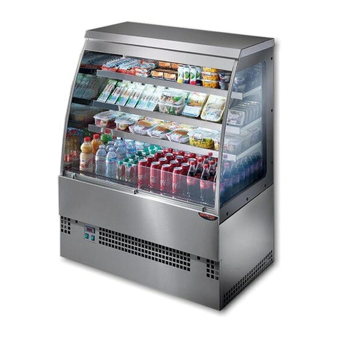
FPG Fusion User manual

Food & Beverage Cabinet

Part No. 22958 Rev. P June 2017 - 2 - Fusion, Food & Beverage Cabinet
Copyright © June 2017 Future Products Group Limited.
All rights reserved.
No part of this publication may be reproduced, stored in a retrieval
system, or transmitted in any form or by any means, electronic,
mechanical, photocopying, recording or otherwise, without the prior
written permission of Future Products Group Ltd.

IN-FUS-HC10 - 3 - © Future Products Group
Table of Contents
INTRODUCTION .................................................................................................................7
Welcome........................................................................................................................................................... 7
Future Products Group (FPG).................................................................................................................... 7
Guidance and Help..................................................................................................................................... 7
Warranty ........................................................................................................................................................... 7
Warranty Period.......................................................................................................................................... 7
Liability Exceptions..................................................................................................................................... 8
Specific Exclusions..................................................................................................................................... 8
Assessment................................................................................................................................................ 8
Time Limit................................................................................................................................................... 8
Caution ....................................................................................................................................................... 8
OPERATION .......................................................................................................................9
Cabinet Layout................................................................................................................................................. 9
Fusion Series Cabinets .............................................................................................................................. 9
Lighting....................................................................................................................................................... 9
Refrigeration Equipment............................................................................................................................. 9
Heated Section........................................................................................................................................... 9
Thermometers............................................................................................................................................ 9
Controls.......................................................................................................................................................... 10
Mains Power............................................................................................................................................. 10
Refrigerated Section Controls .................................................................................................................. 10
Heated Section Controls .......................................................................................................................... 10
Preparation..................................................................................................................................................... 11
Power Supply ........................................................................................................................................... 11
Heating ..................................................................................................................................................... 11
Refrigeration............................................................................................................................................. 11
Defrost Cycle............................................................................................................................................ 11
Load Cabinet............................................................................................................................................ 11
Shelves Positions..................................................................................................................................... 11
Shelf Loading............................................................................................................................................ 11
Operational Routines .................................................................................................................................... 12
After Hours ............................................................................................................................................... 12
Cleaning ................................................................................................................................................... 12
Refrigeration Condensate ........................................................................................................................ 12
Warning- Flammable Products................................................................................................................. 12
Equipment Disposal ...................................................................................................................................... 12
Specialist Disposal ................................................................................................................................... 12
TROUBLE SHOOTING .....................................................................................................13
Dixell XR40CX Alarm Responses................................................................................................................. 14
Probe Faults............................................................................................................................................. 14
HA Alarm .................................................................................................................................................. 14
HA2 Alarm................................................................................................................................................ 14

Part No. 22958 Rev. P June 2017 - 4 - Fusion, Food & Beverage Cabinet
CLEANING........................................................................................................................15
Cautions ......................................................................................................................................................... 15
Power ....................................................................................................................................................... 15
Water........................................................................................................................................................ 15
Exterior ........................................................................................................................................................... 15
Painted and Metal Surfaces..................................................................................................................... 15
Interior............................................................................................................................................................. 15
Condensate Tray...................................................................................................................................... 15
Shelves & Trays ....................................................................................................................................... 15
Cabinet Well............................................................................................................................................. 16
Cooling Fins.............................................................................................................................................. 16
Temperature Probe .................................................................................................................................. 16
Drain Holes............................................................................................................................................... 16
Routines ......................................................................................................................................................... 17
Schedules................................................................................................................................................. 17
Condenser Radiator ................................................................................................................................. 17
ACR Tray.................................................................................................................................................. 17
Warning.................................................................................................................................................... 17
Inspection ................................................................................................................................................. 17
Correction................................................................................................................................................. 17
INSTALLATION ................................................................................................................18
Regulations .................................................................................................................................................... 18
Compliance with Local Requirements...................................................................................................... 18
Operational Safety.................................................................................................................................... 18
Preparation..................................................................................................................................................... 18
Unpacking................................................................................................................................................. 18
Cabinet Preparation.................................................................................................................................. 18
Power Supply ........................................................................................................................................... 18
Earthing .................................................................................................................................................... 18
Equipotential Bonding .............................................................................................................................. 18
Location.......................................................................................................................................................... 19
Ventilation................................................................................................................................................. 19
Access...................................................................................................................................................... 19
Draughts................................................................................................................................................... 19
Level Site.................................................................................................................................................. 19

IN-FUS-HC10 - 5 - © Future Products Group
SERVICING.......................................................................................................................20
Mains Lead ..................................................................................................................................................... 20
Lead Replacement ................................................................................................................................... 20
Lighting........................................................................................................................................................... 20
Protection ................................................................................................................................................. 20
Caution ..................................................................................................................................................... 20
LED Strips ................................................................................................................................................ 20
LED Power Supplies................................................................................................................................. 20
Heating............................................................................................................................................................ 21
Heating Elements..................................................................................................................................... 21
Element Replacement.............................................................................................................................. 21
Temperature Control ................................................................................................................................ 21
Thermometer Battery Replacement......................................................................................................... 21
Control Gear............................................................................................................................................. 22
Ventilation Fan.......................................................................................................................................... 22
Refrigeration .................................................................................................................................................. 22
Caution ..................................................................................................................................................... 22
Access to Control Gear etc. ..................................................................................................................... 22
Access to Condensing Unit etc. ............................................................................................................... 23
Condenser Ventilation.............................................................................................................................. 23
Controller Adjustment............................................................................................................................... 23
Probe Locations........................................................................................................................................ 24
Thermometer............................................................................................................................................ 24
Fan Deck .................................................................................................................................................. 24
Condensate Disposal ............................................................................................................................... 25
ACR Fault Finding Guide ......................................................................................................................... 25
Temperature Regulator XR40CX ............................................................................................................. 26
XR40CX Compressor Control .................................................................................................................. 26
XR40CX Defrost Control .......................................................................................................................... 26
XR40CX Key Functions............................................................................................................................ 27
XR40CX LED Functions........................................................................................................................... 27
XR40CX Min & Max Recorded Temperature.......................................................................................... 28
XR40CX Reset Max/Min Temperature Memory...................................................................................... 28
XR40CX Display the Set-point ................................................................................................................. 28
XR40CX Change the Set-point ................................................................................................................ 28
XR40CX Start a Manual Defrost ............................................................................................................. 28
XR40CX Programming Mode................................................................................................................... 28
XR40CX The Hidden Menu...................................................................................................................... 29
XR40CX Locking and Unlocking the Keyboard........................................................................................ 29
FPG Settings............................................................................................................................................ 30
XR40CX Hot Key..................................................................................................................................... 31
XR40CX Alarm Signals ............................................................................................................................ 32
XR40CX Alarm Recovery......................................................................................................................... 32
XR40CX Other Messages........................................................................................................................ 32
XR40CX Connections .............................................................................................................................. 32

Part No. 22958 Rev. P June 2017 - 6 - Fusion, Food & Beverage Cabinet
SPECIFICATIONS.............................................................................................................33
Mechanical ..................................................................................................................................................... 33
Electrical......................................................................................................................................................... 33
Cabinet Performance..................................................................................................................................... 34
Refrigerated Section Performance........................................................................................................... 34
Controller Settings ........................................................................................................................................ 34
Application Specific Settings .................................................................................................................... 34
XR40CX Settings...................................................................................................................................... 34
Compliance .................................................................................................................................................... 35
Safety Aspects.......................................................................................................................................... 35
Hazardous Substances ............................................................................................................................ 35
Improvements ................................................................................................................................................ 35
On-going Development ............................................................................................................................ 35
ELECTRICAL CIRCUIT DIAGRAM ..................................................................................36
Model: IN-FUS-HC10-A004...................................................................................................................... 36
SPARE PARTS .................................................................................................................37
Cabinet Serial Number............................................................................................................................. 37
MECHANICAL DRAWINGS..............................................................................................38
IN-FUS-HC10-A004.................................................................................................................................. 38

IN-FUS-HC10 - 7 - © Future Products Group
INTRODUCTION
Welcome
COMBINED FOOD & BEVERAGE CABINETS
-
INTRODUCTION
Future
Products
Group (FPG)
Welcome to the world of FPG! Our products are designed and engineered to
give you the optimal performance that you deserve with innovative visual
merchandising appeal.
We are confident that you will be delighted with your state of the art door-less
bottle cooler, and that it will become a valued appliance in your store.
Guidance and
Help
Any new appliance can seem very complex and confusing at first glance. To
ensure you receive the utmost benefit from your new door-less bottle cooler,
there are two things you can do.
Before operating the cabinet, please read the instruction book carefully and
follow its recommendations. The time taken will be well spent. These
instructions both general and technical tell you how to operate and look after
your door-less bottle cooler so that you can receive the full benefits that this
cabinet has to offer.
These instructions cannot, however, cover all eventualities. If you are
unsure of any aspect of the installation, instructions or performance of your
cabinet, contact your dealer promptly or contact us via email to
support@fpgworld.com.
Warranty
COMBINED FOOD & BEVERAGE CABINETS
-
INTRODUCTION
Warranty
Period
Future Products Group Limited warrants, to the original purchaser of an FPG
manufactured door-less bottle cooler that for ONE YEAR (12 months), from the
date of purchase, any defect in workmanship or material resulting in the product
malfunctioning while under correct use will be rectified.
Liability under this warranty is limited to replacing or repairing a part, without
charge.
Continued on next page

Part No. 22958 Rev. P June 2017 - 8 - Fusion, Food & Beverage Cabinet
Warranty cont.
COMBINED FOOD & BEVERAGE CABINETS -INTRODUCTION
Liability
Exceptions
Liability under this warranty does not include:
Any loss, or damage or expenses directly or indirectly arising from use or
inability to use the product or from any other cause.
Any part of the cabinet which has been subject to misuse, neglect,
alteration, incorrect installation, accident, or damage caused by
transportation, use of abrasive chemicals, flooding, fire or acts of God.
Damage, resulting from failure to have the cabinet regularly serviced every
three months by a refrigeration engineer. NB: You will be required to
provide copies of service records in the event of compressor failure.
Any damage or malfunction resulting from the use of non-FPG supplied
spare parts.
Specific
Exclusions
The following are specifically excluded from warranty:
Breakage of glass or plastic components or the replacement of LED lighting
strips or gaskets.
Maladjustment of the electronic refrigeration controller, by an unqualified
person.
Routine compressor / radiator cleaning.
Failure to re-assemble the cabinet correctly after cleaning.
Fair wear and tear.
Assessment
The liability under this warranty is dependent on an assessment by FPG, to
determine the defect in workmanship or materials.
Time Limit
FPG does not guarantee that any service to be performed under this warranty
will be carried out within any particular time limit.
Caution
No warranty claim will be accepted unless authorised by FPG prior to
commencement of service.

IN-FUS-HC10 - 9 - © Future Products Group
OPERATION
Cabinet Layout
COMBINED FOOD & BEVERAGE CABINETS
-
OPERATION
Fusion Series
Cabinets
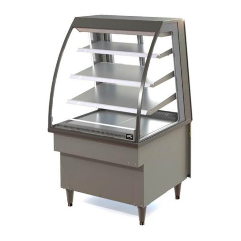
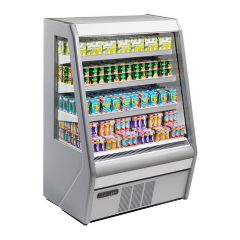
The Fusion Series cabinets are open fronted with closed backs.
The upper section of the cabinet is heated and the lower section is refrigerated.
Although the combined cabinet is constructed as a single unit, each half is
electrically independent, with its own power supply cable and plug.
Lighting
Each half of the cabinet is fitted with high efficiency LED lighting as standard.
The lighting in the cold section is independently controlled, but the lighting in the
heated section is on when the heating is turned on.
Refrigeration
Equipment
The refrigeration equipment is
located in the base of the
cabinet.
The cabinet has openings to
allow adequate ventilation to
ensure efficient performance.
Articles which could restrict
air flow must NOT be placed
against the cabinet.
Heated Section
Heat is provided by radiant elements,
above the shelves, and the lower shelf
is directly heated.
The control for the heated section is on
the back of the cabinet.
A fan circulates air to cool the pelmet,
and this must not be obstructed.
Thermometers
Thermometers are located on the left side, below the heated section and below
the return-air grill of the refrigerated section.
These indicate the operating temperatures of the heated and refrigerated
sections of the cabinet.

Part No. 22958 Rev. P June 2017 - 10 - Fusion, Food & Beverage Cabinet
Controls
COMBINED FOOD & BEVERAGE CABINETS
-
OPERATION
Mains Power
Mains power is independently supplied to each section of the cabinet.
The upper heated section has a readily accessible mains switch on the left of
the pelmet, which controls both heating and lighting.
The refrigerated section has a safety mains isolation switch behind the front
louver panel, but will normally be controlled from the supply socket. The air
circulation and condenser fans will operate as soon as the power is turned on,
but there is a separate switch for the lights, on the left of the upper shelf space.
Refrigerated
Section
Controls
Apart from the light switch,
there are no operator control
switches on the refrigerated
section. It is fully operational as
soon as it is connected to a
mains power point. The control gear is located in
the base of the cabinet.
The controller has indicator displays and
programming buttons.
A safety mains isolator switch is provided for
servicing.
A miniature circuit breaker protects the lighting and
low power devices against overload.
Heated Section
Controls
The mains switch controls both heating and
lighting.
The thermostat for the heated section
is on the back of the cabinet.

IN-FUS-HC10 - 11 - © Future Products Group
Preparation
COMBINED FOOD & BEVERAGE CABINETS
-
OPERATION
Power Supply
Ensure that power is connected to both cabinet sections.
Heating
Use the power switch on the front left of the cabinet to turn on the heating.
The lighting in this section will come on whenever the heating is on.
Refrigeration
The compressor and cabinet fans will run as soon as power is connected.
Use the light switch to control the illumination of the refrigerated section.
As the compressor runs, the cabinet temperature will begin to fall.
The temperature controller is pre-set to maintain products in a chilled state, and
should not need adjustment.
Defrost Cycle
The refrigeration system will automatically defrost periodically. By sensing the
temperature of the cooling fins, the timing and duration of the defrost periods is
optimised and has minimal effect on product temperature.
Load Cabinet
When the appropriate section has reached its operating temperature, load the
cabinet with pre-heated and pre-chilled product.
Hot products must be pre-heated before loading.
Shelves
Positions
The shelf positions are factory set to achieve correct temperature distribution.
Consult FPG if product sizes require shelves to be moved.
Ticketing can be inserted along the front of each shelf.
Shelf Loading
The maximum loading of any shelf must not exceed 15kg of evenly
distributed products.

Part No. 22958 Rev. P June 2017 - 12 - Fusion, Food & Beverage Cabinet
Operational Routines
COMBINED FOOD & BEVERAGE CABINETS
-
OPERATION
After Hours
Products should be removed from the heated section after hours.
This section of the cabinet can then be switched off, to conserve power and
enable cleaning.
If the refrigerated section is left running, turn the lighting off to save power.
Cleaning
Since the cabinet needs to be switched off during cleaning operations, it is best
to clean it at the end of the working day.
The cabinet will then have time to resume its normal operation, before
customers are next expected.
Refrigeration
Condensate
Condensate from the evaporator cooling coils drains into a “boil off” tray, located
under the right hand side of the cabinet.
The element is controlled by a water detection system, to conserve energy use.
The boil off system copes with the condensed water formed under normal
operating conditions. However, as the cabinet is open fronted, the amount of
condensate is affected by atmospheric conditions.
If the cabinet is located in an un-controlled atmosphere, it is possible that in
periods of high humidity, there could be more condensate collected than the boil
off system can remove. This could result in temporary water spillage onto the
floor.
Warning-
Flammable
Products
Do not store explosive substances, such as aerosol cans with a
flammable propellant, in this appliance.
Equipment Disposal
COMBINED FOOD & BEVERAGE CABINETS
-
OPERATION
Specialist
Disposal
Specialist disposal procedures are required for the safe removal of refrigerant
gasses and potentially flammable foam materials.
Pentane, Dimethyl Ether, Isobutene, Butane and Propane may be present.

IN-FUS-HC10 - 13 - © Future Products Group
TROUBLE SHOOTING
FAULT
POSSIBLE CAUSE
REMEDY
Heated section does not
operate
The mains switch is off, circuit
breaker or fuses are off at the
power board
Turn mains switch on and
check circuit breakers and
fuses
Heated section temperature
incorrect
Heating element failed
Check and replace
Incorrect thermostat setting
Adjust (CW to increase temp)
Strong draught
Relocate or shield cabinet
Refrigerated section does not
operate/start
The mains isolating switch on
the wall, circuit breaker or
fuses are off at the power
board
Turn isolating switch circuit
breaker or fuses on
High condenser temperature
Clean condenser radiator
Refrigerated section is not cold
enough
Ventilation grills are blocked
Vacuum or remove blockage
Product blocking air grill
Place product on shelves
Evaporator coil fins blocked
Clean coil fins of debris etc.
Strong draught
Relocate or shield cabinet
Trays obstructing air flow
Re-position trays on shelves
Thermostat needs adjustment
Adjust the controller
Ambient temperature > 25C
Adjust store air conditioning
Evaporator coil iced up
De-ice coil
Condenser radiator blocked
Remove dust and debris
Thermostat faulty
Replace the controller
Temperature probe damaged
Replace temperature probe
Defrost cycle not suitable
Adjust to match
environment
Fans not operating
Have fans checked/replaced
Cabinet lights not working
LED strip has failed
Replace LED strip
Internal circuit breaker has
tripped
Have wiring checked and
reset circuit breaker
Water on floor
Boil off element failed
Have element replaced
Float switch faulty
Have switch replaced
Float switch relay faulty
Have relay replaced
High humidity atmosphere
Temporary condition, no
remedy
Refrigerated section circulation
fan rattling
Build-up of ice in cabinet well
due to blocked drain or cabinet
not being level
Clear drain, level cabinet and
defrost ice
Service
Personnel Only
The table entries in italics indicate actions to be taken only by qualified Service
Personnel.

Part No. 22958 Rev. P June 2017 - 14 - Fusion, Food & Beverage Cabinet
Dixell XR40CX Alarm Responses
COMBINED FOOD & BEVERAGE CABINETS
-
TROUBLE SHOOTING
Probe Faults
P1, P2, P3 or P4 Alarm –Probe fault:
Check appropriate probe wiring and probe resistance. Repair or replace as
required.
HA Alarm
HA Alarm –High cabinet internal temperature alarm:
Clean condenser and condenser pre filter if fitted. Check evaporator coil for ice
build-up and defrost as required. Check for correct air circulation. Check
refrigeration system for correct operation.
HA2 Alarm
HA2 Alarm –High discharge pipe temperature alarm:
Clean condenser and condenser pre filter if fitted. Check condenser fan for
correct operation. Check gas pressures, system may be over charged or low on
refrigerant.

IN-FUS-HC10 - 15 - © Future Products Group
CLEANING
Cautions
COMBINED FOOD & BEVERAGE CABINETS
-
CLEANING
Power
ALWAYS TURN THE POWER SUPPLY OFF BEFORE CLEANING.
Water
THIS UNIT IS NOT WATERPROOF. DO NOT USE A WATER JET SPRAY TO
CLEAN THE INTERIOR OR EXTERIOR OF THIS CABINET.
Exterior
COMBINED FOOD & BEVERAGE CABINETS
-
CLEANING
Painted and
Metal Surfaces
Painted, stainless steel or aluminium surfaces should be cleaned with hot soapy
water or a good quality metal cleaning compound. DO NOT clean surfaces with
abrasive pads or cleaners (e.g. Scotchbrite pads or Jif), as paint, stainless steel
and aluminium surfaces will be damaged.
Interior
COMBINED FOOD & BEVERAGE CABINETS
-
CLEANING
Condensate
Tray
The condensate boil off heater is only designed to handle cooling-coil defrosting
liquid that drains from the well.
DO NOT fill the well with liquid, or attempt to hose it out as the condensate tray
will overflow and leak onto the floor.
Shelves &
Trays
Shelves and trays can be removed for
cleaning.
They should be cleaned with hot soapy
water, or in a dishwasher.
Do not use abrasive pads or cleaners
(e.g. Scotchbrite pads or Jif), as these
may damage surfaces.
Continued on next page

Part No. 22958 Rev. P June 2017 - 16 - Fusion, Food & Beverage Cabinet
Interior cont.
COMBINED FOOD & BEVERAGE CABINETS -CLEANING
Cabinet Well
After removing the trays and
shelves, remove two screws
to allow the fan deck and
coil cover to be lifted off.
Take care not to stretch the
fan leads or damage the coil
fins.
When replacing the fan deck, make sure that it is
correctly located and that the leads are not trapped
by metal parts.
Cooling Fins
If there is debris stuck in the
cooling fins, it is best to use a wet
and dry vacuum cleaner to suck it
out. DO NOT attempt to hose
debris from fins.
Caution: The fins are very sharp.
Take extra care when cleaning
this area.
Temperature
Probe
Take care not to damage or move the
temperature probes, when cleaning the
cooling fins.
Drain Holes
Make sure that the condensate drain in the
cabinet base is free of debris.
If the drains become blocked, and water
cannot drain away, the evaporator cooling
coils may be damaged by a build-up of ice.

IN-FUS-HC10 - 17 - © Future Products Group
Routines
COMBINED FOOD & BEVERAGE CABINETS
-
CLEANING
Schedules
To maintain optimum performance, the following cleaning routine should be
scheduled on a regular basis.
Initially, the following cleaning should be scheduled monthly, but this period may
be adjusted to match the environmental conditions.
Condenser
Radiator
Remove the front grill to
reveal the condenser
radiator.
For efficient refrigeration
performance, the
condenser radiator must
be kept clean, (see
Servicing, Condenser
Radiator).
Regular vacuuming will
prevent a build-up of dust
and fluff, but periodic cleaning of the fins, by a refrigeration engineer, is
recommended.
ACR Tray
Remove any debris that may have
accumulated in the ACR tray.
Warning
Failure to carry out routine cleaning/servicing schedules will void the
warranty on the refrigeration equipment.
Inspection
As part of the cleaning routine, the controls, mechanical parts and electrical
wiring should be inspected for damage, deterioration or need of adjustment.
Correction
If any small faults are found, have them attended to promptly by a competent
serviceman. Don’t wait until they cause a complete breakdown.

Part No. 22958 Rev. P June 2017 - 18 - Fusion, Food & Beverage Cabinet
INSTALLATION
Regulations
COMBINED FOOD & BEVERAGE CABINETS
-
INSTALLATION
Compliance
with Local
Requirements
It is very important that your door-less cabinet is installed correctly and that the
operation is correct before use. Installation must comply with local electrical,
health & safety and hygiene requirements.
Operational
Safety
The appliance is not intended for use by persons (including children) with
reduced physical, sensory or mental capabilities, or lack of experience and
knowledge, unless they have been given supervision or instruction concerning
use of the appliance by a person responsible for their safety. Children should
be supervised to ensure that they do not play with the appliance.
Preparation
COMBINED FOOD & BEVERAGE CABINETS
-
INSTALLATION
Unpacking
Unpack and check unit for damage and report any damage to the carrier and
supplier.
The cabinet is supplied fully assembled. Report any deficiencies to your
supplier.
Cabinet
Preparation
Remove all tapes, ties and packers, used to prevent movement during transit.
Lift out the deck trays and grills to gain access to the cabinet well.
Power Supply
Before connecting to the power supply, check that the local supply is correct to
that shown on the rating plate, located on the rear of the cabinet.
Earthing
WARNING-THIS APPLIANCE MUST BE EARTHED/GROUNDED
Cabinets will usually be earthed via the earth conductors in the three core mains
leads of the refrigerated and heated cabinet sections.
Equipotential
Bonding
An externally accessible terminal is also provided for bonding cabinets together
and to earth.

IN-FUS-HC10 - 19 - © Future Products Group
Location
COMBINED FOOD & BEVERAGE CABINETS
-
INSTALLATION
Ventilation
To assist ventilation, locate the cabinet at least 20mm away from a back wall.
Do not block the front ventilation grill, as this will cause the cabinet to overheat.
The maximum recommended operating ambient temperature is 32°C.
Access
The mains power points supplying the cabinet should be accessible, to allow the
cabinet to be turned off in case of emergency.
The cabinet should also be positioned so the shelves are easily reached for
loading and unloading.
An isolating switch, circuit breaker and controls for the refrigerated section are
behind the front grill.
Draughts
The refrigerated section features an “air curtain” to retain the cold air within the
cabinet. A “curtain” of cold air falls from a linear vent, above the section, to be
re-circulated through the evaporator cooling coils.
The cabinet should not be sited where strong draughts will deflect the “air
curtain”. If this happens, excess condensation will form on the products, and
cooling will be less effective.
Similarly, strong draughts can cause uneven heating in the upper section.
Level Site
Four rollers allow the cabinet to be easily
positioned.
It is important that the cabinet stands level,
so that condensate will drain away from the
well.
If the cabinet is not level, both side to side
and front to back, water may pond under the
circulation fan and freeze. Ice will then build
up into the impellor, which will start making a
loud rattling noise.
Adjust the two front
jacking screws to level
the cabinet.
If the floor is not level,
use shims under one of
the rear rollers.

Part No. 22958 Rev. P June 2017 - 20 - Fusion, Food & Beverage Cabinet
SERVICING
Mains Lead
COMBINED FOOD & BEVERAGE CABINETS
-
SERVICING
Lead
Replacement
The mains leads must only be replaced by the manufacturer, their service agent
or similarly qualified person, in order to avoid a hazard.
Lighting
COMBINED FOOD & BEVERAGE CABINETS
-
SERVICING
Protection
The lighting and low power circuits are protected by a circuit breaker on the
control gear chassis, located behind the front grill of the refrigerated section and
on the back of the heated section.
If the lights do not work but the rest of the cabinet is operating, get an electrician
to check the lighting circuits.
Caution
DO NOT service lights without isolating the cabinet by unplugging it from the
mains supply socket, or turning off the servicing isolation switch.
LED Strips
Light is provided by four strips of LEDs.
Before replacing an LED strip, check the power supply.
Individual LED modules cannot be replaced. A complete
light unit must be used. Note that the light units are not all
the same, so the correct type must be selected.
Remove the plastic cover to access the LED unit.
Connection is made with
a plug and socket.
Disengage the supply
lead from the faulty unit,
and reconnect it to the
replacement unit.
Replace the plastic
cover.
LED Power
Supplies
The LEDs are fed with a 700mA constant current. They consume
approximately 19W per metre of strip length.
The power supplies and driver modules are located on the control gear chassis,
behind the heated section and below the refrigerated section.
Continued on next page
This manual suits for next models
1
Table of contents
Other FPG Display Case manuals

FPG
FPG INLINE 5000C Series User manual

FPG
FPG INLINE 5000C Series User manual

FPG
FPG IN 3H06 User manual

FPG
FPG Visair IN-VH06 User manual

FPG
FPG INLINE 4000S Series User manual

FPG
FPG INLINE 4000S Series User manual

FPG
FPG INLINE 3000S Series User manual

FPG
FPG INLINE 4000S Series User manual

FPG
FPG INLINE 5000C Series User manual

FPG
FPG INLINE 3000S Series User manual
Popular Display Case manuals by other brands

KoolMore
KoolMore MCF-6C user manual

FEDERAL INDUSTRIES
FEDERAL INDUSTRIES IMSS84 Series Installation & operation manual

True
True TCGR-77 Specifications

CombiSteel
CombiSteel 7450.0840 user manual

Bromic Heating
Bromic Heating DD1250SG-NR instruction manual

Polar Electro
Polar Electro DM071 instruction manual