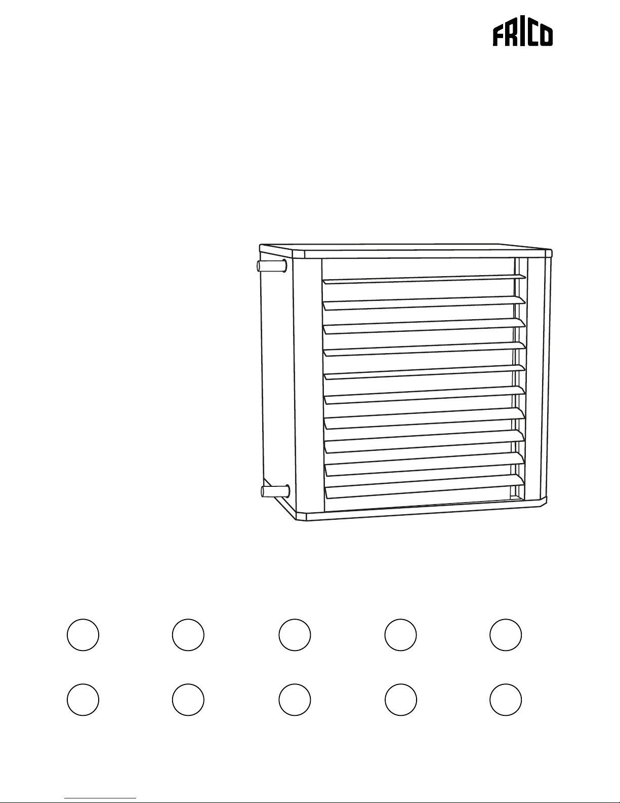
Frico SWXH13 User manual
Other Frico Heater manuals

Frico
Frico Thermozone SF WL Series User manual

Frico
Frico Aquaztrip H User manual

Frico
Frico Thermocassette HC User manual

Frico
Frico Thermozone AR 200 E Series User manual

Frico
Frico Infraglas IHGB12SR User manual

Frico
Frico AR3200C User manual

Frico
Frico Thermoplus User manual

Frico
Frico PF Series User manual

Frico
Frico Infrasmart IHS15W67 User manual

Frico
Frico IRCF15L User manual

Frico
Frico Thermozone AD 400 W Series User manual

Frico
Frico Infralu IHAL Series User manual

Frico
Frico Infracalm INC Series User manual

Frico
Frico RDS User manual

Frico
Frico Thermozone PA3500 User manual

Frico
Frico Thermozone AD Series User manual

Frico
Frico IR3000 User manual

Frico
Frico IRCF3000 Service manual

Frico
Frico Thermozone ADA Cool User manual

Frico
Frico Infradark IND15 User manual


Popular Heater manuals by other brands

oventrop
oventrop Regucor Series quick start guide

Blaze King
Blaze King CLARITY CL2118.IPI.1 Operation & installation manual

ELMEKO
ELMEKO ML 150 Installation and operating manual

BN Thermic
BN Thermic 830T instructions

KING
KING K Series Installation, operation & maintenance instructions

Empire Comfort Systems
Empire Comfort Systems RH-50-5 Installation instructions and owner's manual

Well Straler
Well Straler RC-16B user guide

EUROM
EUROM 333299 instruction manual

Heylo
Heylo K 170 operating instructions

Eterna
Eterna TR70W installation instructions

Clarke
Clarke GRH15 Operation & maintenance instructions

Empire Heating Systems
Empire Heating Systems WCC65 Installation and owner's instructions