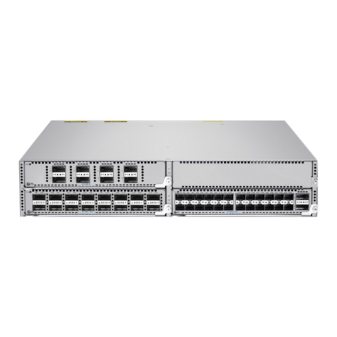
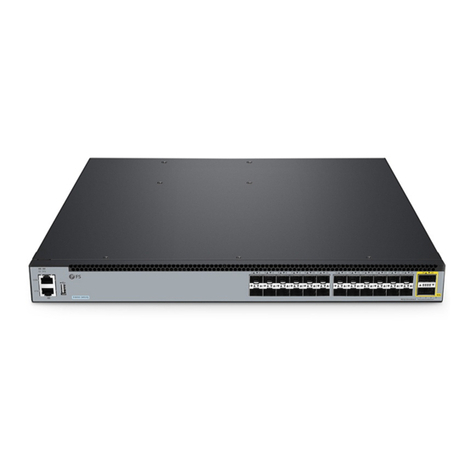
FS SC9405 Series User manual

SC9405 SERIES CORE SWITCHES
SWITCHS CENTRAUX DE LA SÉRIE SC9405
SC9405-SERIE CORE SWITCHES
V1.0
Quick Start Guide
Guide de Démarrage Rapide
Quick Start Anleitung
SC9405
SC9400-48S-E
QSFP28
SC9400
1
2
3
1
2
3
Status
Status
Status
21
2345678
1
43
65 87 109 12
11 14
13 16
15
18
17
20
19
22
21 24
23 26
25 28
27 30
29 32
31
34
33
36
35
38
37 40
39 42
41 44
43 46
45 48
47
21
43
65 87 109 12
11 14
13 16
15
18
17
20
19
22
21 24
23 26
25 28
27 30
29 32
31
34
33
36
35
38
37 40
39 42
41 44
43 46
45 48
47
On=Link Flashing=ACT Green=1000M
On=Link Flashing=ACT Green=1000M Yellow=100M
M
1
M
2
SC9405
SC9400-48S-E
QSFP28
SC9400
1
2
3
1
2
3
Status
Status
Status
21
2345678
1
43
65 87 109 12
11 14
13 16
15
18
17
20
19
22
21 24
23 26
25 28
27 30
29 32
31
34
33
36
35
38
37 40
39 42
41 44
43 46
45 48
47
21
43
65 87 109 12
11 14
13 16
15
18
17
20
19
22
21 24
23 26
25 28
27 30
29 32
31
34
33
36
35
38
37 40
39 42
41 44
43 46
45 48
47
On=Link Flashing=ACT Green=1000M/10G
On=Link Flashing=ACT Green=1000M Yellow=100M
E S D
SC9400-8C-E
M
1
M
2
M
1
M
2
Status Primary Alarm FUNC
FUNC
Status Primary Alarm
MGMT Console
Console
MGMT

EN
1
Introduction
Accessories
Thank you for choosing SC9405 Series Core Switches. This guide is designed to familiarize you with
the layout of the switches and describes how to deploy them in your network.
M6 Screw x12
M6 Nut x12
SC9405
Anti-static Wrist Strap x1
M3 Screw x8
Console Cable x1 Cable Management Bracket x6
Grounding Cable x1
SC9405
SC9400-48S-E
QSFP28
SC9400
1
2
3
1
2
3
Status
Status
Status
21
2345678
1
43
65 87 109 12
11 14
13 16
15
18
17
20
19
22
21 24
23 26
25 28
27 30
29 32
31
34
33
36
35
38
37 40
39 42
41 44
43 46
45 48
47
21
43
65 87 109 12
11 14
13 16
15
18
17
20
19
22
21 24
23 26
25 28
27 30
29 32
31
34
33
36
35
38
37 40
39 42
41 44
43 46
45 48
47
On=Link Flashing=ACT Green=1000M/10G
On=Link Flashing=ACT Green=1000M Yellow=100M
E S D
SC9400-8C-E
M
1
M
2
M
1
M
2
Status Primary Alarm FUNC
FUNCStatus Primary Alarm
MGMT Console
Console
MGMT

EN
2
Front Panel
Hareware Overview
Description
Supervisor module slots
Service module slots
Cable management bracket
Anti-static wrist strap socket
No.
1
2
3
4
Front Panel Ports
3
4
1
2
SC9405
SC9400-48S-E
QSFP28
SC9400
1
2
3
1
2
3
Status
Status
Status
21
2345678
1
43
65 87 109 12
11 14
13 16
15
18
17
20
19
22
21 24
23 26
25 28
27 30
29 32
31
34
33
36
35
38
37 40
39 42
41 44
43 46
45 48
47
21
43
65 87 109 12
11 14
13 16
15
18
17
20
19
22
21 24
23 26
25 28
27 30
29 32
31
34
33
36
35
38
37 40
39 42
41 44
43 46
45 48
47
On=Link Flashing=ACT Green=1000M
On=Link Flashing=ACT Green=1000M Yellow=100M
M
1
M
2
SC9405
SC9400-48S-E
QSFP28
SC9400
1
2
3
1
2
3
Status
Status
Status
21
2345678
1
43
65 87 109 12
11 14
13 16
15
18
17
20
19
22
21 24
23 26
25 28
27 30
29 32
31
34
33
36
35
38
37 40
39 42
41 44
43 46
45 48
47
21
43
65 87 109 12
11 14
13 16
15
18
17
20
19
22
21 24
23 26
25 28
27 30
29 32
31
34
33
36
35
38
37 40
39 42
41 44
43 46
45 48
47
On=Link Flashing=ACT Green=1000M/10G
On=Link Flashing=ACT Green=1000M Yellow=100M
M
1
M
2
E S D
Status Primary Alarm FUNC
FUNCStatus Primary Alarm
MGMT Console
ConsoleMGMT
SC94-EM-A
SC9405
MGMT
Status Primary Alarm FUNC
MGMT Console
Console
MGMT
Console USB
SC9400-8C-E

EN
3
Description
USB
Console
Ports
For storing logs, host version, alarms and other diagnosis information, facilitating online
upgrade of switch software and storage of logs
Using the RS-232 interface level and standard RJ-45 connector for system commissioning,
configuration, maintenance, management, and host software loading
10/100/1000BASE-T Ethernet port, using the RJ-45 connector to load programs
MGMT
SC9400-48F-E
SC9400-48S-E
SC9400-8C-E
Status
21
43
65 87 109 12
11 14
13 16
15
18
17
20
19
22
21 24
23 26
25 28
27 30
29 32
31
34
33
36
35
38
37 40
39 42
41 44
43 46
45 48
47
On=Link Flashing=ACT Green=1000M Yellow=100M
SC9400-48F-E
Status
21
43
65 87 109 12
11 14
13 16
15
18
17
20
19
22
21 24
23 26
25 28
27 30
29 32
31
34
33
36
35
38
37 40
39 42
41 44
43 46
45 48
47
On=Link Flashing=ACT Green=1000M Yellow=100M
SFP
QSFP28
Status
2345678
1
SC9400-8C-E
QSFP28
Status
2345678
1
QSFP28
SC9400-48S-E
Status
21
43
65 87 109 12
11 14
13 16
15
18
17
20
19
22
21 24
23 26
25 28
27 30
29 32
31
34
33
36
35
38
37 40
39 42
41 44
43 46
45 48
47
On=Link Flashing=ACT Green=1000M
SC9400-48S-E
Status
21
43
65 87 109 12
11 14
13 16
15
18
17
20
19
22
21 24
23 26
25 28
27 30
29 32
31
34
33
36
35
38
37 40
39 42
41 44
43 46
45 48
47
On=Link Flashing=ACT Green=1000M/10G
SFP+

EN
Status
Primary MGMT
4
State Description
Status
Primary
LEDs
Off
Off
Off
Off
Solid red
Solid yellow
Blinking
The module is powered off.
Initialization is in progress. Continuous blinking indicates errors.
The switch is operational.
The module is faulty.
The module acts as the standby supervisor module.
The module acts as the primary supervisor module.
No fault.
The whole system or a module fails to work. The device may be
damaged if it continues operating.
The temperature exceeds the threshold but the system continues
operating.
The MGMT port is NOT connected.
The MGMT port is connected at 1000Mbps.
The MGMT port is connected at 10/100Mbps.
The MGMT port is transmitting or receiving data.
Blinking green
Solid green
Green
Yellow
Solid green
Solid red
Alarm
MGMT
Front Panel LEDs
Status Primary Alarm FUNC
MGMT Console
Console
MGMT
Alarm
SC94-EM-A

EN
5
State Description
Status
SFP
LEDs
Off
Off
Off
The module is powered off.
Initialization is in progress. Continuous blinking indicates errors.
The switch is operational.
The module is faulty.
The port link is NOT connected.
The port is connected at 1000Mbps.
The port is connected at 100Mbps.
The port is transmitting and receiving data.
The port link is NOT connected.
The port is connected.
The port is transmitting and receiving data.
Blinking green
Solid green
Solid yellow
Blinking
Blinking
Solid green
Solid green
Solid red
SFP+
State Description
Status
Link/ACT
LEDs
Off
Off
The module is powered off.
Initialization is in progress. Continuous blinking indicates errors.
The switch is operational.
The module is faulty.
The port link is NOT connected.
The port is connected at 1000Mbps.
The port is connected at 100Mbps.
The port is transmitting and receiving data.
Blinking green
Solid green
Solid yellow
Blinking
Solid green
Solid red
SC9400-48F-E
SC9400-48S-E
Status
21
43
65 87 109 12
11 14
13 16
15
18
17
20
19
22
21 24
23 26
25 28
27 30
29 32
31
34
33
36
35
38
37 40
39 42
41 44
43 46
45 48
47
On=Link Flashing=ACT Green=1000M
SC9400-48S-E
Status
21
43
65 87 109 12
11 14
13 16
15
18
17
20
19
22
21 24
23 26
25 28
27 30
29 32
31
34
33
36
35
38
37 40
39 42
41 44
43 46
45 48
47
On=Link Flashing=ACT Green=1000M/10G
Link/ACT
Status
SC9400-48S-E
Status
21
43
65 87 109 12
11 14
13 16
15
18
17
20
19
22
21 24
23 26
25 28
27 30
29 32
31
34
33
36
35
38
37 40
39 42
41 44
43 46
45 48
47
On=Link Flashing=ACT Green=1000M Yellow=100M
SC9400-48F-E
Status
21
43
65 87 109 12
11 14
13 16
15
18
17
20
19
22
21 24
23 26
25 28
27 30
29 32
31
34
33
36
35
38
37 40
39 42
41 44
43 46
45 48
47
On=Link Flashing=ACT Green=1000M Yellow=100M
SFP+
Status

EN
6
State Description
Status
Link/ACT
LEDs
Off
Off
The module is powered off.
Initialization is in progress. Continuous blinking indicates errors.
The switch is operational.
The module is faulty.
The port link is NOT connected.
The port is connected.
The port is transmitting and receiving data.
Blinking green
Solid green
Blinking
Solid green
Solid red
Back Panel
SC9400-8C-E
QSFP28
Status
2345678
1
SC9400-8C-E
QSFP28
Status
2345678
1
Link/ACT
Status
Status
3
4
1
2
Description
Power module slots
Fan tray
Handle of the fan tray
Captive screws of the fan tray
No.
1
2
3
4
NOTE: Ensure the supervisor module, service module, and power supply module are
removed from the enclosure before you move or transport the enclosure.
SC9405

EN
7
Before installation, make sure that you have the following conditions
ready:
Site Environment
Mounting Cable Management Brackets
Installation Requirements
Mounting the Switch
1. Put three cable management brackets on each side respectively. Pay attention to the direction to
mount cable management brackets.
2. Align the screw holes on the cable management bracket with those on the enclosure and tighten
the screws.
Phillips screwdriver.
Standard-sized, 19" wide rack with a minimum of 1U height available in 4-post form hold.
Category 5e or higher RJ-45 Ethernet cables for connecting network devices.
Make sure that the temperature of installation site is maintained at 0°~50°C.
Make sure that the relative humidity of installation site is maintained at 10%~90%.
The installation site must be free from leaking, dripping water or heavy dew.
Keep the installation site dust-free.
The installation site must be well ventilated. Ensure that there is adequate air flow around the
switch. Maintain a minimum clearance of 10cm around the enclosure.
Be sure that the switch is level and stable to avoid any hazardous conditions.
Ensure that the rack and working platforms are well earthed.
SC9405
SC9400-48S-E
QSFP28
SC9400
1
2
3
1
2
3
Status
Status
Status
21
2345678
1
43
65 87 10
912
11 14
13 16
15
18
17
20
19
22
21 24
23 26
25 28
27 30
29 32
31
34
33
36
35
38
37 40
39 42
41 44
43 46
45 48
47
21
43
65 87 109 12
11 14
13 16
15
18
17
20
19
22
21 24
23 26
25 28
27 30
29 32
31
34
33
36
35
38
37 40
39 42
41 44
43 46
45 48
47
On=LinkFlashing=ACT Green=1000M
On=LinkFlashing=ACT Green=1000M Yellow=100M
M
1
M
2
SC9405
SC9400-48S-E
QSFP28
SC9400
1
2
3
1
2
3
Status
Status
Status
21
2345678
1
43
65 87 10
912
11 14
13 16
15
18
17
20
19
22
21 24
23 26
25 28
27 30
29 32
31
34
33
36
35
38
37 40
39 42
41 44
43 46
45 48
47
21
43
65 87 109 12
11 14
13 16
15
18
17
20
19
22
21 24
23 26
25 28
27 30
29 32
31
34
33
36
35
38
37 40
39 42
41 44
43 46
45 48
47
On=LinkFlashing=ACT Green=1000M10G
On=LinkFlashing=ACT Green=1000M Yellow=100M
E S D
M
1
M
2
M
1
M
2
Status Primary Alarm FUNC
FUNC
Status Primary Alarm
MGMT Console
ConsoleMGMT
EN
8
Cabinet Mounting
1. Mount the cabinet at the designed location as planned.
2. Install the appropriate cable management bracket and cables.
3. Install the tray and wiring layer on the rack according to the configuration of one rack with one
cabinet installed or one rack with multiple cabinets installed.
NOTE: Make sure the antistatic wrist strap is grounded well and wear the antistatic wrist
strap in this step and the followings.
1RU
CAUTION: 1. When multiple cabinets are put side by side in the room, they should be aligned
in a straight line, with an error less than 5mm.
2. All wiring inlets at the top and bottom of the cabinet should be installed with
rodent-resistant nets where the seams should be no more than 1.5cm in diameter, to
prevent rodents and other small animals from entering the cabinet.

EN
9
Mounting the Switch to a Cabinet
1. Locate the position on the bracket for installing the slide rail. And locate the position on the other
bracket through the carrying plane.
2. Install seven cage nuts on the marked square holes on each bracket.
3. Place the switch on the sliding rail, and drive it smoothly into the cabinet until the front bracket
reaches the square hole strip.
4. Align the installation holes on the bracket with the cage nuts on the square hole strip, and mount
them with screws.
SC9405
SC9400-48S-E
QSFP28
SC9400
1
2
3
1
2
3
Status
Status
Status
21
2345678
1
43
65 87 109 12
11 14
13 1615
1817
20
19
22
21 2423 26
25 28
27 3029 3231
34
33
36
35
3837 4039 4241 44
43 4645 4847
21
43
65 87 10912
11 14
13 1615
1817
2019
2221 24
23 26
25 28
27 3029 32
31
34
33
3635
38
37 40
39 42
41 44
43 4645 48
47
On=LinkFlashing=ACT Green=1000M
On=LinkFlashing=ACT Green=1000M Yellow=100M
M
1
M
2
SC9405
SC9400-48S-E
QSFP28
SC9400
1
2
3
1
2
3
Status
Status
Status
21
2345678
1
43
65 87 109 12
11 14
13 1615
1817
20
19
22
21 2423 26
25 28
27 3029 3231
34
33
36
35
3837 4039 4241 44
43 4645 4847
21
43
65 87 10912
11 14
13 1615
1817
2019
2221 24
23 26
25 28
27 3029 32
31
34
33
3635
38
37 40
39 42
41 44
43 4645 48
47
On=LinkFlashing=ACT Green=1000M/10G
On=LinkFlashing=ACT Green=1000M Yellow=100M
M
1
M
2
ES D
M
1
M
2
M
1
M
2
Status Primary Alarm FUNC
FUNC
Status Primary Alarm
MGMT Console
ConsoleMGMT

EN
10
Grounding the Switch
1. Remove the two screws on the rear of the switch.
2. Attach the one end of the grounding wire to the switch with the two screws. Connect the other end
of the grounding wire to the grounding wire of the cabinet.
CAUTION: Usually, reserve at least 10mm between the front panel of the equipment and that
of the cabinet after installation. Before mounting into a cabinet, address the following
conditions:
1. Prepare the equipment and move it to the place near the cabinet where you
can handle it easily.
2. Three people are recommended to carry or lift the switch. One is responsible for directing
and the other two carrying or lifting the switch.
CAUTION: 1. The switch must be well-grounded. The grounding resistance shall be less
than 1Ω.
2. The earth connection must not be removed unless all supply connections have been
disconnected.
3. The cross-sectional area of protective earthing conductor shall be at least 2.5mm² (12AWG).
Status

Power
Status
12
EN
11
Connecting the Power
Installing Fans
1. Loosen the captive screws on the blank panel covering the power slot at the rear of the enclosure.
2. Insert the power module into the slot along the rail until the power module clicks into place.
CAUTION: 1. Do not install power cord while the power is on.
2. Please make sure that the interval between two operation is greater than 30 seconds to hot
swap a power supply.
3. Please do not touch the connecting finger part of the power supply which is removed after
power off in case that capacitor discharge is not full.
Power
Status
1 2

EN
12
Installing Modules
1. Install the fan tray into the fan slot in the rear panel. Note the direction identifier of the fan tray’s
name to ensure the correct direction.
2. Tighten the captive screws on the fan tray with a screwdriver.
1. Pull out both levers.
2. Insert the module into the slot along the rail and drive it ahead smoothly.
3. Push both levers toward the slot.
4. Tighten captive screws on both sides of the panel.
CAUTION: Do not remove the fan tray forcibly. You can use the fan handle. Otherwise,
component damage may occur, which causes deformation of the fan tray, and the fan tray
cannot be removed.
SC9405
SC9400-48S-E
QSFP28
SC9400
1
2
3
1
2
3
Status
Status
Status
21
2345678
1
43
65 87 10
912
11 14
13 16
15
18
17
20
19
22
21 24
23 26
25 28
27 30
29 32
31
34
33
36
35
38
37 40
39 42
41 44
43 46
45 48
47
21
43
65 87 109 12
11 1413 16
15
18
17
20
19
22
21 24
23 26
25 28
27 30
29 32
31
34
33
36
35
38
37 40
39 42
41 44
43 46
45 48
47
On=LinkFlashing=ACT Green=1000M
On=LinkFlashing=ACT Green=1000M Yellow=100M
M
1
M
2
SC9405
SC9400-48S-E
QSFP28
SC9400
1
2
3
1
2
3
Status
Status
Status
21
2345678
1
43
65 87 10
912
11 14
13 16
15
18
17
20
19
22
21 24
23 26
25 28
27 30
29 32
31
34
33
36
35
38
37 40
39 42
41 44
43 46
45 48
47
21
43
65 87 109 12
11 1413 16
15
18
17
20
19
22
21 24
23 26
25 28
27 30
29 32
31
34
33
36
35
38
37 40
39 42
41 44
43 46
45 48
47
On=LinkFlashing=ACT Green=1000M/10G
On=LinkFlashing=ACT Green=1000M Yellow=100M
M
1
SC9405
SC9400-48S-E
QSFP28
SC9400
1
2
3
1
2
3
Status
Status
Status
21
2345678
1
43
65 87 10
912
11 14
13 16
15
18
17
20
19
22
21 24
23 26
25 28
27 30
29 32
31
34
33
36
35
38
37 40
39 42
41 44
43 46
45 48
47
21
43
65 87 109 12
11 14
13 16
15
18
17
20
19
22
21 24
23 26
25 28
27 30
29 32
31
34
33
36
35
38
37 40
39 42
41 44
43 46
45 48
47
On=LinkFlashing=ACT Green=1000M
On=LinkFlashing=ACT Green=1000M Yellow=100M
M
1
M
2
SC9405
SC9400-48S-E
QSFP28
SC9400
1
2
3
1
2
3
Status
Status
Status
21
2345678
1
43
65 87 10
912
11 14
13 16
15
18
17
20
19
22
21 24
23 26
25 28
27 30
29 32
31
34
33
36
35
38
37 40
39 42
41 44
43 46
45 48
47
21
43
65 87 109 12
11 14
13 16
15
18
17
20
19
22
21 24
23 26
25 28
27 30
29 32
31
34
33
36
35
38
37 40
39 42
41 44
43 46
45 48
47
On=LinkFlashing=ACT Green=1000M/10G
On=LinkFlashing=ACT Green=1000M Yellow=100M
E S D
E S D
M
1
M
2
M
1
M
2
Status Primary Alarm FUNC
FUNC
Status Primary Alarm
MGMT Console
ConsoleMGMT
M
1
M
2
M
1
M
2
Status Primary Alarm FUNC
FUNC
Status Primary Alarm
MGMT Console
ConsoleMGMT
SC9405
SC9400-48S-E
QSFP28
SC9400
1
2
3
1
2
3
Status
Status
Status
21
2345678
1
43
65 87 10
912
11 14
13 16
15
18
17
20
19
22
21 24
23 26
25 28
27 30
29 32
31
34
33
36
35
38
37 40
39 42
41 44
43 46
45 48
47
21
43
65 87 109 12
11 14
13 16
15
18
17
20
19
22
21 24
23 26
25 28
27 30
29 32
31
34
33
36
35
38
37 40
39 42
41 44
43 46
45 48
47
On=Link Flashing=ACT Green=1000M
On=Link Flashing=ACT Green=1000M Yellow=100M
M
1
M
2
Status Primary Alarm Reset MGMT Console
2
1
SC9405
SC9400-48S-E
QSFP28
SC9400
1
2
3
1
2
3
Status
Status
Status
21
2345678
1
43
65 87 10
912
11 14
13 16
15
18
17
20
19
22
21 24
23 26
25 28
27 30
29 32
31
34
33
36
35
38
37 40
39 42
41 44
43 46
45 48
47
21
43
65 87 109 12
11 14
13 16
15
18
17
20
19
22
21 24
23 26
25 28
27 30
29 32
31
34
33
36
35
38
37 40
39 42
41 44
43 46
45 48
47
On=Link Flashing=ACT Green=1000M
On=Link Flashing=ACT Green=1000M Yellow=100M
M
1
M
2
Status Primary Alarm Reset MGMT Console
4
3

EN
13
Installing Swappable Interface Modules (Optional)
Installing the SFP+/SFP Modules
Wear an anti-static wrist strap and tighten the lock properly grounded. Install the SFP+/SFP/QSFP+
module. Do not touch the connecting finger.
CAUTION: 1. Do not hold the edge or collide the components on the PCB. Do not touch the
connecting finger on the modules.
2. Do not plug/unplug a supervisor module, service module or switch fabric module with
force, use the ejector.
3. If any module slot is unoccupied, install a filler panel to ensure proper airflow.
SC9405
SC9400-48S-E
QSFP28
SC9400
1
2
3
1
2
3
Status
Status
Status
21
2345678
1
43
65 87 10
912
11 14
13 16
15
18
17
20
19
22
21 24
23 2625 28
27 3029 32
31
3433
36
35
38
37 40
39 4241 44
43 46
45 48
47
21
43
65 87 10912
11 1413 16
15
18
17
20
19
2221 2423 26
25 28
27 30
29 32
31
34
33
36
35
38
37 40
39 42
41 44
43 46
45 48
47
On=Link Flashing=ACT Green=1000M
On=Link Flashing=ACT Green=1000M Yellow=100M
M
1
M
2
SC9405
SC9400-48S-E
QSFP28
SC9400
1
2
3
1
2
3
Status
Status
Status
21
2345678
1
43
65 87 10
912
11 14
13 16
15
18
17
20
19
22
21 24
23 2625 28
27 3029 32
31
3433
36
35
38
37 40
39 4241 44
43 46
45 48
47
21
43
65 87 10912
11 1413 16
15
18
17
20
19
2221 2423 26
25 28
27 30
29 32
31
34
33
36
35
38
37 40
39 42
41 44
43 46
45 48
47
On=Link Flashing=ACT Green=1000M/10G
On=Link Flashing=ACT Green=1000M Yellow=100M
M
1
M
2
E S D
SC9405
SC9400-48S-E
QSFP28
SC9400
1
2
3
Status
Status
Status
21
2345678
1
43
65 87 10
912
11 14
13 16
15
18
17
20
19
22
21 24
23 2625 28
27 3029 32
31
3433
36
35
38
37 39
21
43
65 87 109 12
11 1413 16
15
18
17
20
19
2221 2423 26
25 28
27 30
29 32
31
34
33
36
35
38
37 39
On=Link Flashing=ACT Green=1000M
On=Link Flashing=ACT Green=1000M Yellow=100M
SC9405
SC9400-48S-E
QSFP28
SC9400
1
2
3
Status
Status
Status
21
2345678
1
43
65 87 10
912
11 14
13 16
15
18
17
20
19
22
21 24
23 2625 28
27 3029 32
31
3433
36
35
38
37 39
21
43
65 87 109 12
11 1413 16
15
18
17
20
19
2221 2423 26
25 28
27 30
29 32
31
34
33
36
35
38
37 39
On=Link Flashing=ACT Green=1000M/10G
On=Link Flashing=ACT Green=1000M Yellow=100M

EN
14
Installing the SFP+ Cables
Installing QSFP28 Modules
1. Push the module gently into the SFP+ module slot until a click is heard.
2. Connect the copper module to the Ethernet network through the connector, and the Link/ACT
status is on.
3. Use an SFP+ cable to connect two SFP+ ports close to each other: Plug the SFP+ cable to the SFP+
port through the connector. Pay attention to the proper end for connection.
1. Turn up the handle of the module into the top bail-clasp latch. Hold both sides and push the
module into place with a click sound.
2. Use the fiber optical patch cord to connect the SFP/SFP+ module to the fiber optical network.
Select the patch cord with the connector corresponding to the port and the Link/ACT Status LED is on.
1
2
3
40
39 4241 44
43 46
45 48
47
40
39 42
41 44
43 46
45 48
47
M
1
M
2
1
2
3
40
39 4241 44
43 46
45 48
47
40
39 42
41 44
43 46
45 48
47
M
1
M
2
SC9405
SC9400-48S-E
QSFP28
SC9400
1
2
3
Status
Status
Status
21
2345678
1
43
65 87 10
912
11 14
13 16
15
18
17
20
19
22
21 24
23 2625 28
27 3029 32
31
3433
35
21
43
65 87 109 12
11 1413 16
15
18
17
20
19
2221 2423 26
25 28
27 30
29 32
31
34
33
36
35
On=Link Flashing=ACT Green=1000M
On=Link Flashing=ACT Green=1000M Yellow=100M
SC9405
SC9400-48S-E
QSFP28
SC9400
1
2
3
Status
Status
Status
21
2345678
1
43
65 87 10
912
11 14
13 16
15
18
17
20
19
22
21 24
23 2625 28
27 3029 32
31
3433
35
21
43
65 87 109 12
11 1413 16
15
18
17
20
19
2221 2423 26
25 28
27 30
29 32
31
34
33
36
35
On=Link Flashing=ACT Green=1000M
On=Link Flashing=ACT Green=1000M Yellow=100M
SC9405
SC9400-48S-E
QSFP28
SC9400
1
2
3
Status
Status
Status
21
2345678
1
43
65 87 10
912
11 14
13 16
15
18
17
20
19
22
21 24
23 2625 28
27 3029 32
31
3433
36
35
38
37 40
39 4241 44
43 45
21
43
65 87 109 12
11 1413 16
15
18
17
20
19
2221 2423 26
25 28
27 30
29 32
31
34
33
36
35
38
37 40
39 42
41 44
43 45
On=Link Flashing=ACT Green=1000M/10G
On=Link Flashing=ACT Green=1000M Yellow=100M

15
EN
Installing QSFP28 Cables
1. Turn up the handle of the module into the top bail-clasp latch. Hold both sides and push the
module into place with a click sound.
2. Push the module gently into the QSFP28 module slot until a click is heard.
3. Use the fiber optical patch cord to connect the QSFP28 module to the fiber optical network. Select
the patch cord with the connector corresponding to the port, and the Link/ACT Status LED is on.
Hold the connector of a copper cable module with one hand and carry the cable to the front panel
with the other. Push the module gently into the QSFP28 module slot until a click is heard, and the
Link/ACT Status LED is on.
1
2
3
36
35
38
37 40
39 4241 44
43 46
45 48
47
36
38
37 40
39 42
41 44
43 46
45 48
47
M
1
M
2
1
2
3
36
35
38
37 40
39 4241 44
43 46
45 48
47
36
38
37 40
39 42
41 44
43 46
45 48
47
M
1
M
2
1
2
3
46
45 48
47
46 48
47
M
1
M
2
1
2
3
46
45 48
47
46 48
47
M
1
M
2
SC9405
SC9400-48S-E
QSFP28
SC9400
1
2
3
Status
Status
Status
21
2345678
1
43
65 87 10
912
11 14
13 16
15
18
17
20
19
22
21 24
23 2625 28
27 3029 32
31
3433
36
35
38
37 40
39 4241 43
21
43
65 87 109 12
11 1413 16
15
18
17
20
19
2221 2423 26
25 28
27 30
29 32
31
34
33
36
35
38
37 40
39 42
41 43
On=Link Flashing=ACT Green=1000M
On=Link Flashing=ACT Green=1000M Yellow=100M
SC9405
SC9400-48S-E
QSFP28
SC9400
1
2
3
Status
Status
Status
21
2345678
1
43
65 87 10
912
11 14
13 16
15
18
17
20
19
22
21 24
23 2625 28
27 3029 32
31
3433
36
35
38
37 40
39 4241 43
21
43
65 87 109 12
11 1413 16
15
18
17
20
19
2221 2423 26
25 28
27 30
29 32
31
34
33
36
35
38
37 40
39 42
41 43
On=Link Flashing=ACT Green=1000M/10G
On=Link Flashing=ACT Green=1000M Yellow=100M
SC9405
SC9400-48S-E
QSFP28
SC9400
1
2
3
Status
Status
Status
21
2345678
1
43
65 87 10
912
11 14
13 16
15
18
17
20
19
22
21 24
23 2625 28
27 3029 32
31
3433
36
35
38
37 40
39 4241 43
21
43
65 87 109 12
11 1413 16
15
18
17
20
19
2221 2423 26
25 28
27 30
29 32
31
34
33
36
35
38
37 40
39 42
41 43
On=Link Flashing=ACT Green=1000M
On=Link Flashing=ACT Green=1000M Yellow=100M
SC9405
SC9400-48S-E
QSFP28
SC9400
1
2
3
Status
Status
Status
21
2345678
1
43
65 87 10
912
11 14
13 16
15
18
17
20
19
22
21 24
23 2625 28
27 3029 32
31
3433
36
35
38
37 40
39 4241 43
21
43
65 87 109 12
11 1413 16
15
18
17
20
19
2221 2423 26
25 28
27 30
29 32
31
34
33
36
35
38
37 40
39 42
41 43
On=Link Flashing=ACT Green=1000M/10G
On=Link Flashing=ACT Green=1000M Yellow=100M

16
EN
Connecting the Console Port
Connecting the MGMT Port
1.Insert the RJ-45 connector of the console cable into the console port of the switch.
2.Connect the DB9 female connector of the console cable to the serial port of the computer.
1. Connect one end of a standard RJ-45 Ethernet cable to the MGMT port of the switch.
2. Connect the other end of the cable to a computer.
1
2
3
44 46
45 48
47
44 46
45 48
47
M
1
M
2
1
2
3
44 46
45 48
47
44 46
45 48
47
M
1
M
2
1
2
3
44 46
45 48
47
44 46
45 48
47
M
1
M
2
1
2
3
44 46
45 48
47
44 46
45 48
47
M
1
M
2
SC9405
SC9400-48S-E
QSFP28
SC9400
1
2
3
1
2
3
Status
Status
Status
21
2345678
1
43
65 87 10
912
11 14
13 16
15
18
17
20
19
22
21 24
23 2625 28
27 3029 32
31
3433
36
35
38
37 40
39 4241 44
43 46
45 48
47
21
43
65 87 109 12
11 1413 16
15
18
17
20
19
2221 2423 26
25 28
27 30
29 32
31
34
33
36
35
38
37 40
39 42
41 44
43 46
45 48
47
On=Link Flashing=ACT Green=1000M
On=Link Flashing=ACT Green=1000M Yellow=100M
M
1
M
2
SC9405
SC9400-48S-E
QSFP28
SC9400
1
2
3
1
2
3
Status
Status
Status
21
2345678
1
43
65 87 10
912
11 14
13 16
15
18
17
20
19
22
21 24
23 2625 28
27 3029 32
31
3433
36
35
38
37 40
39 4241 44
43 46
45 48
47
21
43
65 87 109 12
11 1413 16
15
18
17
20
19
2221 2423 26
25 28
27 30
29 32
31
34
33
36
35
38
37 40
39 42
41 44
43 46
45 48
47
On=Link Flashing=ACT Green=1000M/10G
On=Link Flashing=ACT Green=1000M Yellow=100M
M
1
M
2
Status Primary Alarm Reset
MGMT Console
ConsoleMGMT
SC9405
SC9400-48S-E
QSFP28
SC9400
1
2
3
1
2
3
Status
Status
Status
21
2345678
1
43
65 87 10
912
11 14
13 16
15
18
17
20
19
22
21 24
23 2625 28
27 3029 32
31
3433
36
35
38
37 40
39 4241 44
43 46
45 48
47
21
43
65 87 109 12
11 1413 16
15
18
17
20
19
2221 2423 26
25 28
27 30
29 32
31
34
33
36
35
38
37 40
39 42
41 44
43 46
45 48
47
On=Link Flashing=ACT Green=1000M
On=LinkFlashing=ACT Green=1000M Yellow=100M
M
1
M
2
SC9405
SC9400-48S-E
QSFP28
SC9400
1
2
3
1
2
3
Status
Status
Status
21
2345678
1
43
65 87 10
912
11 14
13 16
15
18
17
20
19
22
21 24
23 2625 28
27 3029 32
31
3433
36
35
38
37 40
39 4241 44
43 46
45 48
47
21
43
65 87 109 12
11 1413 16
15
18
17
20
19
2221 2423 26
25 28
27 30
29 32
31
34
33
36
35
38
37 40
39 42
41 44
43 46
45 48
47
On=Link Flashing=ACT Green=1000M/10G
On=LinkFlashing=ACT Green=1000M Yellow=100M
M
1
M
2
Status Primary Alarm Reset
MGMT Console
ConsoleMGMT
EN
Connecting the USB Port
Configuring the Switch via the Web-based Interface
Insert the Universal Serial Bus (USB) flash disk to the USB port for software and configuration backup
and offline software upgrade.
Step 1: Connect the computer to the Management port of the switch using the network cable.
?x
OK Cancel
General
IP address:
Subnet mask:
Default gateway:
You can get IP settings assigned automatically if your network
supports this capability. Otherwise, you need to ask your network
administrator for the appropriate IP settings.
Internet Protocol Version 4(TCP/IPv4) Properties
Use the following IP address:
Obtain an IP address automatically
Preferred DNS server:
Alternate DNS server:
Validate settings upon exit Advanced...
. . . 21168192
0255
255255
. . .
. . .
. . .
. . .
Obtain DNS server address automatically
Use the following DNS server addresses:
SC9405
SC9400-48S-E
QSFP28
SC9400
1
2
3
1
2
3
Status
Status
Status
21
2345678
1
43
65 87 10
912
11 14
13 16
15
18
17
20
19
22
21 24
23 2625 28
27 3029 32
31
3433
36
35
38
37 40
39 4241 44
43 46
45 48
47
21
43
65 87 109 12
11 1413 16
15
18
17
20
19
2221 2423 26
25 28
27 30
29 32
31
34
33
36
35
38
37 40
39 42
41 44
43 46
45 48
47
On=Link Flashing=ACT Green=1000M
On=Link Flashing=ACT Green=1000M Yellow=100M
M
1
M
2
SC9405
SC9400-48S-E
QSFP28
SC9400
1
2
3
1
2
3
Status
Status
Status
21
2345678
1
43
65 87 10
912
11 14
13 16
15
18
17
20
19
22
21 24
23 2625 28
27 3029 32
31
3433
36
35
38
37 40
39 4241 44
43 46
45 48
47
21
43
65 87 109 12
11 1413 16
15
18
17
20
19
2221 2423 26
25 28
27 30
29 32
31
34
33
36
35
38
37 40
39 42
41 44
43 46
45 48
47
On=Link Flashing=ACT Green=1000M/10G
On=Link Flashing=ACT Green=1000M Yellow=100M
M
1
M
2
Status Primary Alarm Reset
MGMT Console
ConsoleMGMT
Configuring the Switch
17

EN
Configuring the Switch via the Console Port
Step 2: Set the IP address of the computer to 192.168.1.x. (“x”is any number from 2 to 254.)
Step 3: Open a browser, type http://192.168.1.1, and enter the default username and password,
admin/admin.
Step 4: Click Login to display the web-based configuration page.
Step 1: Connect a computer to the switch's console port using the console cable.
Step 2: Start the terminal simulation software such as HyperTerminal on the computer.
IE 8/9/10/11, Google Chrome, Firefox are supported
Login
admin
*****
x
Quick Connect
Protocol: Serial
Flow Control
DTR/DSR
RTS/CTS
XON/XOFF
Save sessionShow quick connect on startup
Open in a tab
Connect Cancel
COM3
9600
8
None
1
Port:
Baud rate:
Data bits:
Parity:
Stop bits:
Name of pipe:
18

EN
AC Power Module Does Not Work
Power LED Working Abnormally
Step 3: Set the parameters of the HyperTerminal: 9600 bits per second, 8 data bits, no parity, 1 stop
bit and no flow control.
Step 4: After setting the parameters, click Connect to enter.
1. Place the switches of all the power modules to OFF.
2. Check if the cables have been correctly connected. Check whether the power cables are tightly
connected to the power sockets and modules. Check whether the power modules are installed
correctly. If necessary, pull out the power modules and check whether the connectors on the
backboard of the power system are tightened.
1. Check if the service module is firmly inserted. If so, install the service module again and ensure that
it is inserted into place before you tighten the fastening screws.
2. If the service module still does not work, check if the connector of the slot on the backplane is
loose. If yes, insert the service module to another slot for a try. If the slot and connection are not the
cause, return the service module for repair.
Fan Tray Does Not Work
Check if the connection between the fan tray and the backplane is secure and if the connector gets
loose. If the connection is secure, you need to replace the fan tray.
Serial Port Console Has No Output
1. Check whether serial port cables are connected correctly and whether the connected serial port is
identical with that configured on the super terminal.
2. Check whether the configuration of the serial port is the same as that described in Software
Configuration Guide. If not, modify the serial port configuration parameters.
No Characters/Distorted Characters are Displayed on the Screen of the
Terminal Device
1. Check whether the console cable is correctly connected.
2. Check whether the console cable is broken.
3. Check whether the console port of the switch is the same as the port of the terminal device.
4. Check whether the console port configuration of the terminal device is correct.
Troubleshooting
19
This manual suits for next models
4
Table of contents
Languages:
Other FS Switch manuals

FS
FS S5800 Series User manual

FS
FS S3700-24T4F User manual

FS
FS NC8200 Series User manual

FS
FS S5500-48T8SP User manual

FS
FS S3700-24T4F Instruction Manual

FS
FS S5900-24S4T2Q User manual

FS
FS S5850-24S2C-DC User manual

FS
FS S2805S Series User manual

FS
FS S3910 Series User manual

FS
FS S5500-48T8SP User manual
Popular Switch manuals by other brands

Cypress
Cypress CLUX-41SY Operation manual

Accton Technology
Accton Technology ETHERHUB-16MI+ E0398-R01 Advanced reference guide

airnet
airnet AIR-SW8P user guide

Grundfos
Grundfos MS1 Installation and operating instructions

HP
HP ProCurve 408 installation guide

Lectrosonics
Lectrosonics MM8 operating instructions