iii
• In general, sheaths of the control signal wires are not specifically designed to withstand a high voltage
(i.e., reinforced insulation is not applied). Therefore, if a control signal wire comes into direct contact
with a live conductor of the main circuit, the insulation of the sheath might break down, which would
expose the signal wire to a high voltage of the main circuit. Make sure that the control signal wires will
not come into contact with live conductors of the main circuit.
Doing so could cause an accident or an electric shock.
• Before changing the switches, turn OFF the power and wait at least 10 minutes. Further, make sure,
using a multimeter or a similar instrument, that the DC link bus voltage between the terminals P(+) and
N(-) has dropped to the safe level (+25 VDC or below).
Otherwise, an electric shock could occur.
• The inverter, motor and wiring generate electric noise. Be careful about malfunction of the nearby
sensors and devices. To prevent them from malfunctioning, implement noise control measures.
Otherwise an accident could occur.
• The leakage current of the EMC filter built-in type of inverters is comparatively large. Be sure to perform
protective grounding.
Otherwise, an accident or an electric shock could occur.
Operation
• Be sure to mount the front cover before turning the power ON. Do not remove the cover when the
inverter power is ON.
Otherwise, an electric shock could occur.
• Do not operate switches with wet hands.
Doing so could cause electric shock.
• If the auto-reset function has been selected, the inverter may automatically restart and drive the motor
depending on the cause of tripping. Design the machinery or equipment so that human safety is
ensured at the time of restarting.
Otherwise, an accident could occur.
• If the stall prevention function (current limiter), automatic deceleration (anti-regenerative control), or
overload prevention control has been selected, the inverter may operate with acceleration/deceleration
or frequency different from the commanded ones. Design the machine so that safety is ensured even in
such cases.
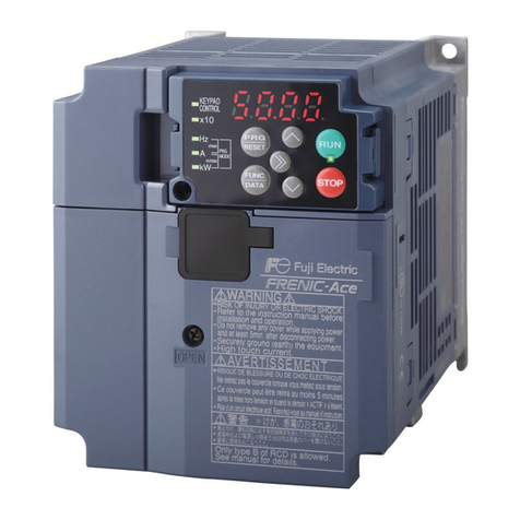
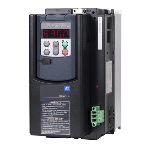
• The key on the keypad is effective only when the keypad operation is enabled with function code
F02 (= 0, 2 or 3). When the keypad operation is disabled, prepare an emergency stop switch separately
for safe operations.
Switching the run command source from keypad (local) to external equipment (remote) by turning ON
the "Enable communications link" command LE disables the key. To enable the key for an
emergency stop, select the STOP key priority with function code H96 (= 1 or 3).
• If any of the protective functions have been activated, first remove the cause. Then, after checking that
the all run commands are set to OFF, release the alarm. If the alarm is released while any run
commands are set to ON, the inverter may supply the power to the motor, running the motor.
Otherwise, an accident could occur.
