manuals.online logo
Brands
  1. Home
  2. •
  3. Brands
  4. •
  5. Full Gauge Controls
  6. •
  7. Temperature Controllers
  8. •
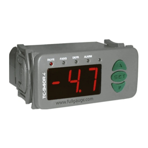
  9. Full Gauge Controls TC-940Ri plus User manual

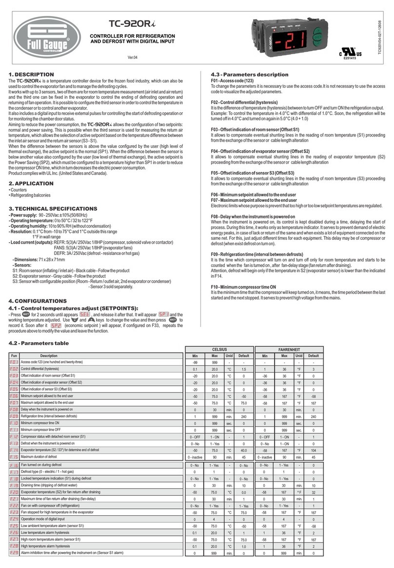
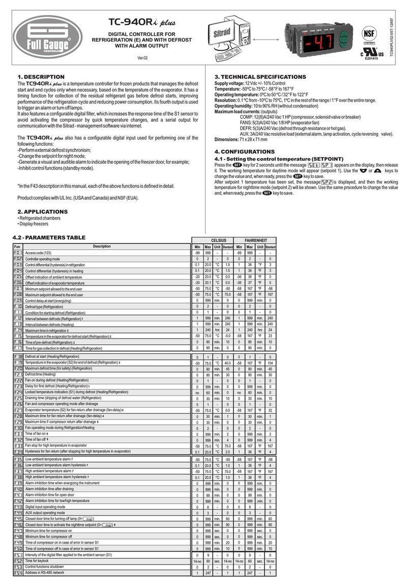
Full Gauge Controls TC-940Ri plus User manual

Ver.01
DIGITAL CONTROLLER FOR
REFRIGERATION AND DEFROST
WITH ALARM OUTPUT
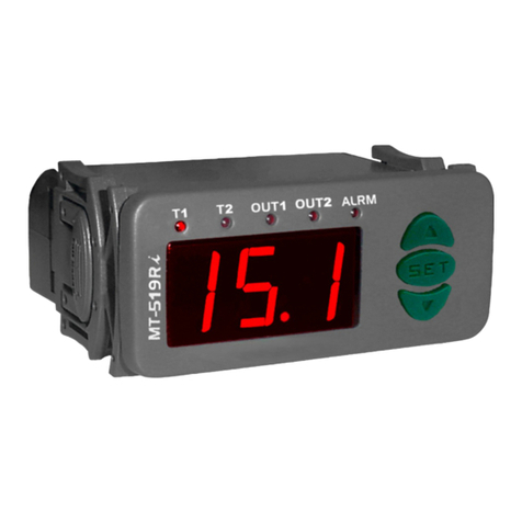
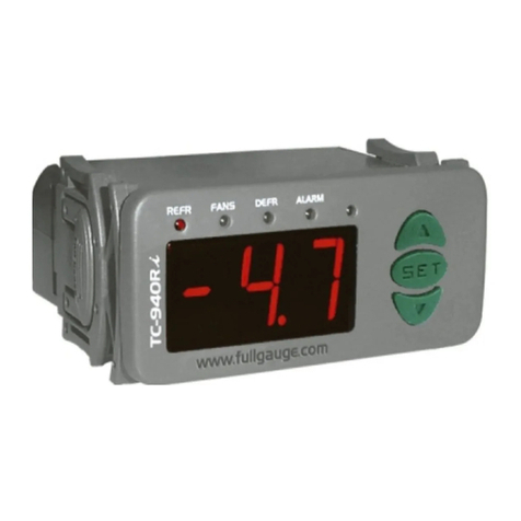
TC-940Ri plus
COMP
1.DESCRIPTION
2.APPLICATION
3.TECHNICAL SPECIFICATIONS
The isatemperaturecontrollerthatmanagecyclesofdefrost,startandfinish,when
only necessary, based in evaporator temperature, and they have one output for alarm or shutdown
lamps.Theyhavefunctiontowait residualrefrigerantfluidreturnsindefrost.Thus,itispossibletosave
energyandincreasetheefficiencyofthesystem.
The have one digital input for extern synchronize defrost. This same input can
change setpoint to nigthtime mode. This digital input can generate a visual and audible alarm too, to
indicateopendoor,forexemple.
The haveadigitalfilterthatsimulatesanincreaseresponsetimeof sensor S1 to
avoidthecompressoractioninfastchangesoftemperature.
TheyhaveoneserialporttocomunicatewhithSitrad .
•Counters
•Refrigeratedbalcony
12 dc-50to75°C/-58to167°F
0.1°Cfrom-10to75°Cand1°Coutsidethisrange / 1°F
0to50°C 32to122°F
10to90%RH(withoutcondensation)
71x28x71mm
COMP:16(8)A/250Vac1HP(compressor,solenoidvalveorcontactor)
FANS:5(3)A/250Vac1/8HP(evaporatorfans)
DEFR:5(3)A/250Vac(defrost-resistanceorhotgas)
ALRM:3A/250Vacresistiveload(externalalarm)
TC-940Ri plus
TC-940Ri plus
TC-940Ri plus
®
-Powersupply:
-Controltemperature:
-Resolution:
-Operatingtemperature: /
-Operatinghumidity:
-Dimensions:
-Loadcurrent(outputs):
V
4.CONFIGURATIONS
4.1-Settingthecontrol temperature (SETPOINT)
Press for two seconds, until the message appears, and then release. The current working
temperaturewillbedisplayed.Usethekeys and tochangethevalueandthenpress to
save.
Iftheoperatingmodeofthedigitalinput isconfiguredfornighttimesetpoint(F31=3),themessage
willbedisplayedafterthemessage toallowsettingthedaytimesetpoint.Usethekeys or
tochangethevalueandthenpress tosave.Then willbedisplayedtoallowsettingthe
nighttimesetpoint,usethesameprocedureabovetoadjustitandleavethesetupmode.
SET
SET
SET
4.3-Parameters description
F01-Accesscode(123)
F02-Controldifferential(hysteresis)
F03- ambient
F05-Minimumsetpointallowedtotheenduser
F06-Maximumsetpointallowedtothe enduser
F07-Defrosttype
F08-Initialdefrostcondition
F09-Periodbetweendefrosts(ifF08=0)
F10-Maximumtimeinrefrigeration(forsecurity,ifF08=1)
F11-Temperatureintheevaporatorfordefroststart(ifF08=1)
F12-Timeofpre-defrost(ifF08=1)
F13-Defrostwhentheinstrumentispoweredon
F14-Evaporatortemperature(S2)forenddefrost
F15-Maximumdefrostduration
F16-Fanturnedonduringdefrost
F17-Delaytodofirstdefrost(ifF08=0
F18-Lockedtemperatureindication(S1)duringdefrost
F19-Drainingtime(drippingofdefrostwater)
F20-Evaporatortemperature(S2)forfanreturnafterdraining(fan-delay)
It is necessary to change the configuration parameters. To visualize the adjusted parameters, it is not
necessarytoinsertthisaccesscode.
Itisthedifferenceoftemperature(hysteresis)betweenONandOFFtherefrigeration.
Youneedtocontroltemperaturein4.0ºCwithdifferentialof1.0ºC.
So,therefrigerationisturnedoffin4.0ºCandwillbeturnedonin5.0ºC(4.0+1.0).
Itallowstocompensateeventualshutinglineson reading of ambient temperature (S1), proceedingof
sensorexchangeorcablelengthalteration.
Itallowstocompensateeventualshutinglineson reading of ambient temperature (S2), proceedingof
sensorexchangeorcablelengthalteration.
Itistopreventthatincorrecthighorlowtemperaturesberegulated.
“0”=Electricaldefrost(resistances),whereiskeptononlythedefrostoutput.
“1”=Hotgasdefrost,wheredefrostandcompressoroutputsarekepton.
Itdefinesifthedefroststartwillbefortemperature or time. Is this function has the value“1”,whenthe
evaporator temperature reaches the configured value in “F11” the instrument starts to count the pre-
defrosttimeand,after,willdothedefrost.
Itdeterminesthetime betweentwoconsecutivesdefrost cycles,andstartsto becountedfromthe last
defrost.Attention,thedefrostonlywillstartifthetempertureinS2(evaporatorsensor)islowerthanF14.
It acts as security time (if F08 = 1) and evaporator temperature will not reach the configured value in
“F11”.Thisfunctiondeterminesthemaximumtimethatcontrollerwillstaywithoutdefrost.
When evaporator temperature reaches the configured value in this function the controller will start to
countthepre-defrostperiod(F12).
Atthemoment thatthetemperature inevaporatordecreasesandreachestheconfigured valuein“F11”,
start to be counted the pre-defrost time. During the pre-defrost stage, if the temperature is kept low the
defrost starts, else if the temperature increase at least 1 ºC in relation to configured value, the system
returnstorefrigerationstage.
Itpossibilitiesthedefrostatthemomentthatthe controlleristurnedon,forexample,inreturnofelectrical
energy(incaseofenergylacks).
If evaporator temperature (sensor S2) reaches the adjusted value, the end defrost will happen for
temperature.Withthis,thedefrostprocessisoptimized.
This function serves to adjust the maximum value of time to defrost. If in this period the evaporator
temperaturewillnotreachtheconfiguredvalueinF14apointwillbeblinkingoninferiordownrightsideof
displayindicatingthattheenddefrostocurredfortimeandnotfortemperature.
This can happen when the adjusted temperature is very high, the limit time will be not enough, the S2
sensorisdetachedornotincontactwiththeevaporator.
Itpossibilitiesthefanfunctioningduringdefrost.
)
Thisfunctiondefinesanextratimethattheinstrumentwillkeepinrefrigerationbeforedothefirstdefrost,
topreventthatlotofcountersenterindefrost at the same time. Thistimeonlyappearsbeforethefirst
defrost,whenF08=0(initialdefrostfortime).
This function prevents that ambient temperature elevation be visualized. During defrost the last
measured temperature in refrigeration cycle will be locked on display. The indication will be released
whenthistemperaturewillbereachedagainor15minutesafterthebeginofnextrefrigerationcycle.
Necessary time for dripping, it means, to drain the last water drops of the evaporator.All the outputs
keepturnedoff.Ifyoudonotneedthisstage,adjustthistimefor”zero”.
Afterthedraining,thefan-delaycyclestarts.Therefrigeration(COMP)outputisturnedon,becausethe
evaporatortemperatureishigh,butthefanonlyisturnedonafterevaporatortemperaturedecreasesthe
adjustedvalue.Thisprocessisnecessarytoremovetheheatthatexistsintheevaporatorbecausethe
defrost,preventingtopassittotheambient.
Example:
Indicationoffsetofthe temperature
F04-Indicationoffsetoftheevaporatortemperature
Example: Naturaldefrostorby resistances installed outsidetheevaporator.
TC940PLV01-01T-11744
Access code: 123 (one hundred and twenty-three)
Control differential (hysteresis)
Offset indication for ambient sensor
Indication offset of the evaporator temperature (offset)
Minimum setpoint allowed to the end user
Maximum setpoint allowed to the end user
Defrost type (0 = resistance; 1 = hot gas)
Initial defrost condition (0 = time; 1 = temperature)
Period between defrost (if F08 = 0)
Maximum time in refrigeration (for security, if F08 = 1)
Temperature in the evaporator for defrost start (if F08 = 1)
Time of pre-defrost (if F08 = 1)
Defrost when the instrument is powered on (0 - no;1-yes)
Evaporator temperature (S2) for end defrost
Maximum defrost duration (for security)
Fan turned on during defrost (0 - no;1-yes)
Delay to do the first defrost (if F07 = 0)
4.2-Parameters table CELSIUS
Fun FAHRENHEIT
0
0
0
1
9
247
-
-
-
1
0
1
0
0
0
1
9
247
-
-
-
1
0
1
Compressor status with detached ambient sensor
(0=off;1=on)
Intensity of the digital filter applied to ambient sensor (S1)
Network equipment address RS - 485
Locked temperature indication (S1) during defrost (0 - no;1-yes)
Draining time (dripping of defrost water)
Evaporator temperature (S2) for fan return after draining
Maximum time for fan return after draining (fan-delay)
Fanonwithcompressoroff(0-no;1-yes)
Fan stop for high temperature in evaporator
Hysteresis for fan return (after stoping for high temperature
in evaporator)
Low temperature alarm (S1)
Alarm hysteresis of low temperature
High temperature alarm (S1)
Alarm hysteresis of high temperature
Inhibition time of alarm when the instrument is powered on
Inhibition time of alarm after draining
Digital input operating mode
Time for inhibiting the open door alarm
Time for collecting the defrost gas
Delay when the instrumet is powered on
Minimum time of compressor turned on
Minimum time of compressor turned off
Description Min Max Unit
Standard
Min Max Unit
Standard
-99
0.1
-20
-20
-50
-50
0
0
1
1
-50
0
0
-50
0
0
0
999
20.0
20.0
20.0
75.0
75.0
1
1
999
240
75.0
90
1
75.0
90
1
999
-
°C
°C
°C
°C
°C
-
-
min.
hours
°C
min.
-
°C
min.
-
min.
-
1.5
0.0
0.0
-50
75.0
0
0
240
24
-5.0
10
0
40.0
45
0
0
-99
1
-36
-36
-58
-58
0
0
1
1
-58
0
0
-58
0
0
0
999
36
36
36
167
167
1
1
999
240
167
90
1
167
90
1
999
-
°F
°F
°F
°F
°F
-
-
min.
hours
°F
min.
-
°F
min.
-
-
-
3
0
0
-58
167
0
0
240
24
23
10
0
104
45
0
0
0
0
-50
0
0
-50
0.1
-50
0.1
-50
0.1
0
0
0
0
0
0
0
0
1
30
75.0
30
1
75.0
20.0
75.0
20.0
75.0
20.0
999
999
3
99
90
999
999
999
-
min.
°C
min.
-
°C
°C
°C
ºC
°C
°C
min.
min.
-
min.
min.
min.
sec.
ec.s
0
10
0.0
1
1
75.0
2.0
-50
1.0
75.0
1.0
0
0
0
0
0
0
0
0
0
0
-58
0
0
-58
1
-58
1
-58
1
0
0
0
0
0
0
0
0
1
30
167
30
1
167
36
167
36
167
36
999
999
3
99
90
999
999
999
-
min.
°F
min.
-
°F
°F
°F
ºF
°F
°F
min.
min.
-
min.
min.
min.
sec.
sec.
0
10
32
1
1
167
4
-58
2
167
2
0
0
0
0
0
0
0
0
F21-Maximumtimeforfanreturnafterdraining(fan-delay)
F22-Fanonwithcompressoroff
F23-Fanstopforhightemperatureinevaporator
F24-Hysteresisforfan-delay(afterstoppingforhightemperatureinevaporator)
F25-Lowtemperaturealarm(S1)
F26-Alarmhysteresisoflowambienttemperature
F27-Hightemperaturealarm(S1)
F28-Alarmhysteresisofhightemperature
F29-Inhibitiontimeofalarmwhentheinstrumentispoweredon
F30-Inhibitiontimeofalarmafterdraining
F31-Digitalinputoperatingmode
F32-Timeforinhibitingtheopendooralarm
F33-Timeforcollectingthedefrostgas
F34-Delaywhentheinstrumentispoweredon
F35-Minimumtimeofcompressorturnedon
F36-Minimumtimeofcompressorturnedoff
F37-Compressorstatuswithdetachedambientsensor(S1)
ambient (S )
F39-NetworkequipmentaddressRS-485
For security, if the evaporator temperature does not reach the adjusted value in F20 or the S2 sensor is
detached,thefan-delaywillhappenafterpassedtheadjustedtimeinthisfunction.
Duringrefrigeration,thefancanbedependofthecompressorstatus.
”0”=Thefankeepsturnedonwhilecompressoristurnedon(thisalternative,insomecases,
Possibilitiesagreateconomyofelectricalenergy).
”1”=Thefankeepsturnedonduringallrefrigerationcycle.
This function cycles the evaporator fan until that ambient temperature approaches of the temperature
desired in the refrigerating installation project. This preventing high temperature and suction pressures
that can damage the compressor. If the temperature in evaporator pass the adjusted value, the fan is
turnedoff,turningonagainwithaconfigurablehysteresisinF24.
It allows to determine the difference of temperature to fan-delay had to a stop for temperature above
desiredinevaporator.
If the ambient temperature (sensor S1) decreases above this point during refrigeration, this will be
signalizedthroughthemessage ondisplayandtheoutput(NO/NC)ofalarmwillbeturnedon.
Itisthedifferenceoftemperaturetoturnoffthealarmoutputforlowambienttemperature.
If the ambient temperature (sensor) reaches this point during the refrigeration, this will be signalized
throughthemessage ondisplayandtheoutput(NO/NC)ofalarmwillbeturnon.
Itisthetemperaturetoturnoffthealarmoutputforhighambienttemperature.
Duringthistimethealarmiskeptturnedoffwaitingthatthesystemstartstoworking.
Thisfunctionservestoinhibit thealarmduringaperiod afterdraining,becauseitis normalanelevationof
thetemperatureproceedingofthedefrost.
Thedigitalinputcanbeconfiguredtooperateasfollows:
0=none;
1=defrostsynchronization;
2=opendooralarm,
3=nighttimesetpoint.
Duringthistimethedooropenalarmiskeptoff.
Afterstarting thedefrostthecontrollerwillkeeponlythefanonforthistimetousetheremainingenergyof
thegas.
Whentheinstrumentis turned on,itcankeep a timewithitscontrol disabled, delayingtheprocessinitial.
Duringthistime itfunctionsonlyas temperatureindicator.It servestopreventdemand peaksofelectrical
energy,incaseoflackorreturnofthesame,whenalotofequipmentsare connectedinthesameline.For
this, adjust different times for each equipment. This delay can be of compressor or defrost (when exists
defrostonstart).
Itisthetimethatthecompressorwillkeepturnedon,itmeans,thetimeperiodbetweenthelaststartedand
thenextstopped.
Itisthe minimumtimethat thecompressorwill keepturnedoff, itmeans,the timeperiodbetween thelast
stopped and the next started. It serves to alliviate the pressure and to increase the useful life of the
compressor.
If the ambient sensor (S1) is detached or out specified range, the compressor assumes the configured
statusinthisfunction.
Forcountersthat storage fruitsitisbetter thatthecompressorkeeps turnedoff,but incounters
thatstoragemeatsitisbetterthatthecompressorkeepsturnedon.
Equipment's network address for communicating with Sitrad software.
Note: One network must not have different equipment with the same address.
Exemple:
®
.
F38-Intensityofthedigitalfilterappliedtothe sensor 1
This filter aims at simulating an increase of environment sensor (S1) mass, thus increasing its response
time (thermal inertia). The larger the value adjusted in this function, the longest the response time of
sensorS1.
Atypicalapplicationrequiringthisfilteristhefreezerforicecreamorfrozengoods,becausewhenthedoor
isopenedahotairmassreachesthesensordirectly,causingaquickriseintheindicationofthemeasured
temperature,causingthecompressortobeactivatedunnecessarilymanytimes.
5.4-Initialdefrost condition
Thefunction “F08”determinesifthestartofthedefrostwillbefortimeortemperature.
Thestartofdefrostwillhappenafterelapsedtheconfiguredtimein .
Whenthetemperatureintheevaporatorreachestheconfiguredvaluein ,the
count of pre-defrost period will start (F12). After elapsed this time, if the temperature keeps low the
defrostwillstart.Ifthetemperature increases,thecontrollerreturnstorefrigerationstage.
F08=0 F09
F08=1 F11
5.5-Howtodetermine the end defrostfortemperature
a)
b)
c)
Adjustthefollowfunctionswithmaximumvalues:
-Intervalbetweendefrosts(F09=999min)
-Evaporatortemperatureforenddefrost(F14=75ºC)
-Defrostmaximumduration(F15=90min)
Waituntilanicelayertobecreatedontheevaporator.
Doamanualdefrost,pressing for4seconds,untilappear .
d)
e)
F)
g)
h)
COMP:
FANS:
DEFR:
ALRM:
Observethemeltingprocess.
Waituntilmeltalldefrostonevaporatortoconsiderthedefrostfinalized.
CheckthetemperatureinevaporatorreadbythesensorS2atthismoment,pressing andcopy
thisvaluetothefunctionF14-Evaporatortemperature(S2)forenddefrost.
Assecurity,adjustagainthefunctionF15- Maximumdurationofdefrost,thatdependsofthedefrost
type.
NowadjustthefunctionF09-Intervalbetweendefrostsasdesiredvalue.
Todoamanualdefrost,regardlessoftheprogramming,keeppressed for4seconds,untilappears
theindication .
If the instrument is in defrost and you want to finish it, follow the above instructions, until appears the
indication .
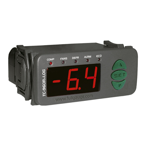
Theledsindicatethecontroloutputsstatus:
Compressororsolenoidofliquidgas
Evaporatorfans
Defrost(resistancesorhotgas)
Alarmoutput
Exemple: Electrical defrost (resistance) = 45 minutes as maximum
Defrost for hot gas = 20 minutes as maximum
5.6-Manualdefrost
5.7-IndicatorsandAlarms
Detachedambientsensorortemperature(S1)outtherange
Detachedevaporatorsensorortemperature(S2)outtherange
Lowambienttemperaturealarm
Highambienttemperaturealarm
Alwaysthatthedefrostisfinishedbytimeandnotfortemperatureapointlocatedonrightinferior
sideofdisplaywillbeblinkinguntilthenextdefrost,indicatingthat:
-Theintervalbetweendefrostistoolong.
-Thereareburnedresistances
-Thehotgasisnotcirculating
-Thereisaninoperativefan
-Theadjustedtimeformaximumdurationofdefrostisshort.
Invalidconfigurationparameters.
-Inthissituationtheoutputswillbeturnedoff.
-Checkwhichparameterhaveinvalidinformationandcorrectittoreturntonormaloperation.
4.3.1-Unitselection(ºC/ºF)
5.OPERATION
5.1-Parameters visualization
To determine the unit that the instrument will work, access the function “F01” with the access cod 231 and
confirmwiththekey .Pressthekey . willappear.Press thanuse or tochoose
between or andconfirmwith .Afterselecttheunit willappearandtheinstrument
returnstothefunction“F01”.Everytimethattheunitischanged,theparametersmustbeconfiguratedagain,
becausetheyassumethestandardvalues(item4.2).
Pressatthesametimethekeys and for2secondsuntilappear ,releasingthemafterthat.
Soon,appears .
Usethekeys and toaccessthedesiredfunction.
Afterselectthefunction,press (shorttouch)tovisualizetheconfiguredvalue.
Pressagain (shorttouch)toreturnthefunctionsmenu.
Toresetthemenuandreturntonormaloperation(temperatureindication),press untilappear .
a)
b)
c)
d)
e)
SET SET
SET
SET
SET
SET
5.2-Parameters alteration
a)
b)
c)
d)
e)
AccessthefunctionF01pressingatthesametime and for2secondsuntilappear ,
releasingthenafterthat.Soonwillappear ,andthenpress (shorttouch).
Use and toentertheaccesscode(123),andthenpress .
Select the desired function and visualize the configured value, like explained the itens“5.1-b” and
“5.1-c”.
Use and tochangethevalueandthenpress torecordtheconfiguredvalueandreturn
tothefunctionsmenu.
To reset themenuandreturntonormal operation (temperature indication), press until appear
.
Press .The stage of the process will appear, the elapsed time (in minutes) and evaporator
temperature(S2).
Incaseofdetachedsensorortemperatureoutspecifiedrangewillappear .
Processstages: Initialdelay(delaytostartthecontrol)
Fan-delay(delaytofanreturn)
Refrigeration
Pre-defrost(onlyifF08=1)
Defrost
Draining
5.3 - Process stage, elapsed time and evaporator temperature (S2)
SET
SET
SET
SET
FAN-DELAY REFRIGERATION DEFROST DRAINING
PRE-DEFROST
5.9-Alarminhibition
Toinhibitthealarmoutputpressthekey .Themessages willappear.
Aftertheinhibition,thealarmoutputreturnstobeenabledwhentheinstrumentleavesthealarmstatus.
SET
AA
BB
AB
RS-485
®
AA
BB
AB
AA
BB
AB
RS-485
SERIAL
Brown - A
Red - B
TC-940Ri plus
SERIAL
Brown - A
Red - B
TC-940Ri plus
5.8-Registers of minimumand maximumtemperatures
Press .Willappear andminimumandmaximumtemperaturesofblacksensor(ambient).After
appear andminimumandmaximumtemperaturesofgraysensor(evaporator).
Toresettheregisters,keeppressed duringvisualizationofminimumandmaximumtemperatures
untilappear .
Note:
Power
supply
6. WIRING DIAGRAM
COMP
DEFR
FANS
COMUM
1245678910 11 12
3
12
45678910 11 12
3
ALRM
Digital input B
A
IN
GND
Sensor
gray cable (evaporator)
2
Sensor
black cable (ambient)
1
Loads
supply
Over the specifield current
use a contactor.
To the terminal of
the distribution box
Integrating Controllers, RS-485 Serial Interface and Computer
Serial interface
RS-485
Full Gauge
External
mesh terminal
grounded
RS-485SerialInterface
®
Device used to establish the
connectionFullGaugeControls’
instrumentswiththeSitrad .
Distribution Box
Used to connect more than one instrument to the Interface. The
wire'sconnectionsmustbemadeinagreementwiththe following
rules: terminal of the instrument connects to the terminal of
thedistributionbox,thatmustbeconnectedwiththeterminal of
theInterface.Repeattheactionforterminals and ,being
thecableshield.
AA
A
B
the terminal of distribution box must be connected to the
respectiveterminals ofeachinstrument.
Serial
communication
RS-485
Serial
communication
RS-485
IMPORTANT
1:
2:
3:
AccordingtothechaptersofnormIEC60364:
Install onthepowersupply
Sensorcablesand signalcablesof thecomputermay bejoined,but notinthesameelectricconduit
throughwhichtheelectricinputandtheactivationoftheloadsrun
Install transient suppresors (RC filters) parallel to the loads as to increase the product life of the
relays.
protectoragainstovervoltage
For more information, please contact our Technical Support by e-mail: or by
phone +55 51 3475.3308 [email protected]
Schematic for the connection of supresors
to contactors
Suppresor
A1
A2
A1 and A2 are the
contactor coil terminals.
Schematic for the connection of supresors to
direct activation loads
Load
Suppresor
For direct activation the maximum
specified current should be taken
into consideration.
Note:Thesensorcablelenghtcanbeincreasedbytheuseruntil200metersusing2x24AWGcable.
PROTECTIVE :VINYL
This adhesive vinyl (included inside the packing) protects the instruments against
waterdrippings,asincommercialrefrigerators,forexample.Dotheapplicationafter
finishingtheelectricalconnections.
Remove the protective paper
andapplythevinylontheentire
superior part of the device,
foldingtheflapsasindicatedby
thearrows.
72 mm
Dimension of the clipping
for setting of the instrument
in panel
29 mm
12Vdc
5.10-Inhibitionof thealarmsound
To inhibit the audible alarm press the key for two seconds. After the inhibition, the audible alarm
returnstobeenabledwhentheinstrumentleavesthealarmstatus.
Serial
communication
RS-485

Other Full Gauge Controls Temperature Controllers manuals

Full Gauge Controls TC-940Ri User manual

Full Gauge Controls

Full Gauge Controls TC-940Ri User manual

Full Gauge Controls MT-516RVTi plus User manual

Full Gauge Controls

Full Gauge Controls MT-516RVTi plus User manual

Full Gauge Controls TC-940Ri plus User manual

Full Gauge Controls

Full Gauge Controls TC-940Ri plus User manual

Full Gauge Controls MT-519Ri User manual

Full Gauge Controls

Full Gauge Controls MT-519Ri User manual

Full Gauge Controls Evolution MT-514 E User manual

Full Gauge Controls

Full Gauge Controls Evolution MT-514 E User manual

Full Gauge Controls TC-940Ri Plus User manual

Full Gauge Controls

Full Gauge Controls TC-940Ri Plus User manual

Full Gauge Controls MT-511C Manual

Full Gauge Controls

Full Gauge Controls MT-511C Manual

Full Gauge Controls MT-526C User manual

Full Gauge Controls

Full Gauge Controls MT-526C User manual

Full Gauge Controls MT-512Ri plus User manual

Full Gauge Controls

Full Gauge Controls MT-512Ri plus User manual

Full Gauge Controls TC-960Ri LOG User manual

Full Gauge Controls

Full Gauge Controls TC-960Ri LOG User manual

Full Gauge Controls TC-920Ri User manual

Full Gauge Controls

Full Gauge Controls TC-920Ri User manual

Full Gauge Controls MT-512Ri LOG User manual

Full Gauge Controls

Full Gauge Controls MT-512Ri LOG User manual

Full Gauge Controls MT-512E 2HP User manual

Full Gauge Controls

Full Gauge Controls MT-512E 2HP User manual

Full Gauge Controls MT-512Ri LOG User manual

Full Gauge Controls

Full Gauge Controls MT-512Ri LOG User manual

Full Gauge Controls MICROSOL II plus User manual

Full Gauge Controls

Full Gauge Controls MICROSOL II plus User manual

Full Gauge Controls MT-512Ri LOG User manual

Full Gauge Controls

Full Gauge Controls MT-512Ri LOG User manual

Full Gauge Controls MICROSOL II plus User manual

Full Gauge Controls

Full Gauge Controls MICROSOL II plus User manual

Popular Temperature Controllers manuals by other brands

Bosch FR 120 Installation and operating instructions

Bosch

Bosch FR 120 Installation and operating instructions

ISG INFRASYS E380 operating manual

ISG INFRASYS

ISG INFRASYS E380 operating manual

THORLABS TCLDM9 operating manual

THORLABS

THORLABS TCLDM9 operating manual

YOKOGAWA UP150 user manual

YOKOGAWA

YOKOGAWA UP150 user manual

Savannah STOKER v4 instruction manual

Savannah

Savannah STOKER v4 instruction manual

SkyLink TS-101 user manual

SkyLink

SkyLink TS-101 user manual

Sub-Zero CRC-2052 user manual

Sub-Zero

Sub-Zero CRC-2052 user manual

eltherm ELTC/L-15 Operation manual

eltherm

eltherm ELTC/L-15 Operation manual

Nibe CDS 10 Installer manual

Nibe

Nibe CDS 10 Installer manual

Siemens RLA162 installation instructions

Siemens

Siemens RLA162 installation instructions

Honeywell R7500C installation instructions

Honeywell

Honeywell R7500C installation instructions

Ascon tecnologic e33B operating instructions

Ascon tecnologic

Ascon tecnologic e33B operating instructions

Rheem Raypack Temp-Tracker B-40 Installation & operating instructions

Rheem

Rheem Raypack Temp-Tracker B-40 Installation & operating instructions

MDT Technologies SCN-RT2UP.01 manual

MDT Technologies

MDT Technologies SCN-RT2UP.01 manual

Viconics VTR8300 Series Application guide

Viconics

Viconics VTR8300 Series Application guide

Smart Controller MyTemp user manual

Smart Controller

Smart Controller MyTemp user manual

ENDA EDT1323 quick start guide

ENDA

ENDA EDT1323 quick start guide

Lennox COMFAIR HH Series Installation, operating and maintenance manual

Lennox

Lennox COMFAIR HH Series Installation, operating and maintenance manual

manuals.online logo
manuals.online logoBrands
  • About & Mission
  • Contact us
  • Privacy Policy
  • Terms and Conditions

Copyright 2025 Manuals.Online. All Rights Reserved.