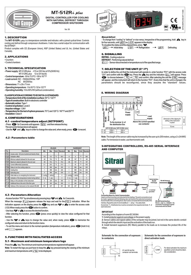
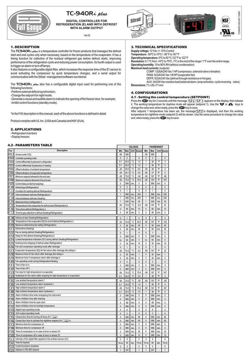
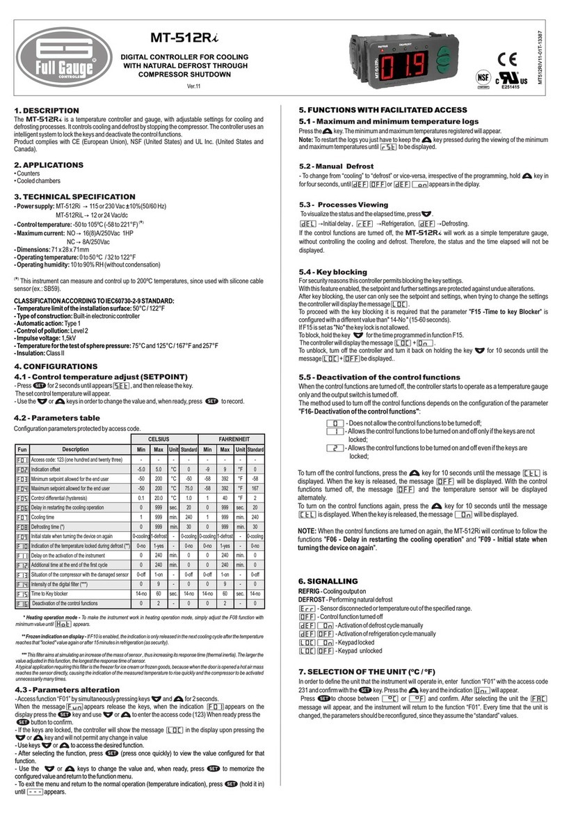
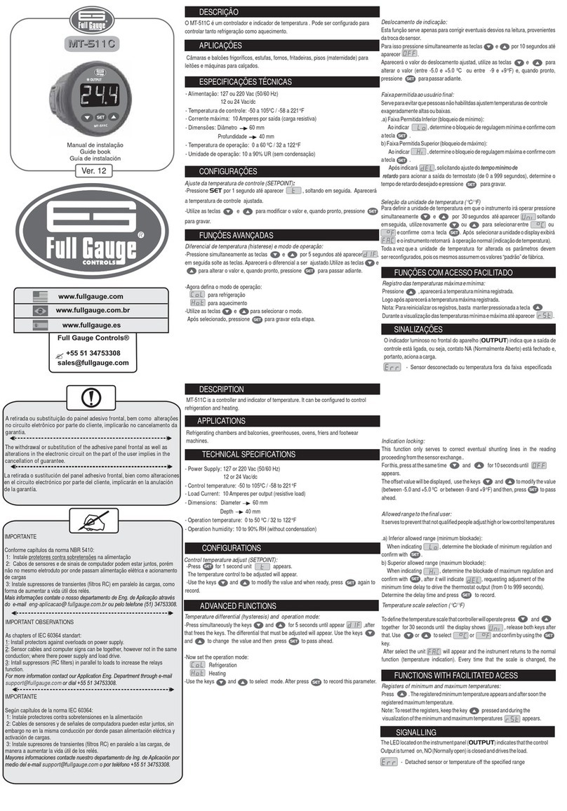
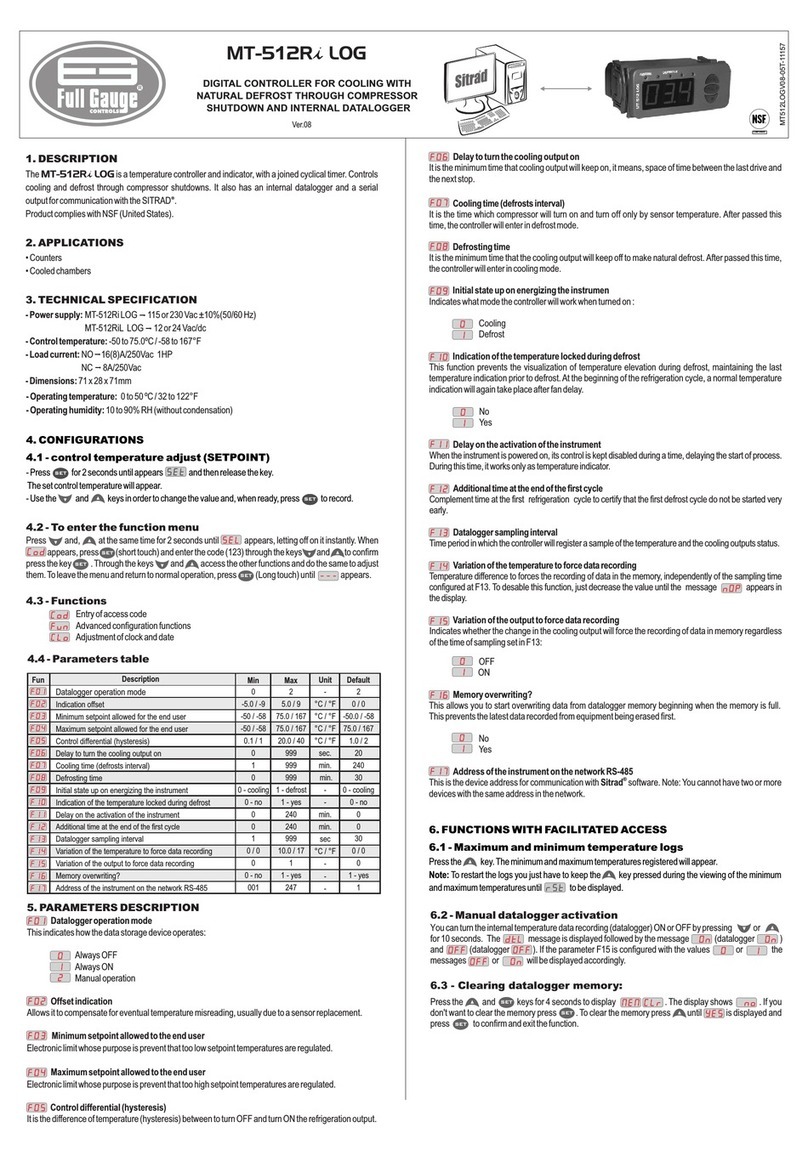
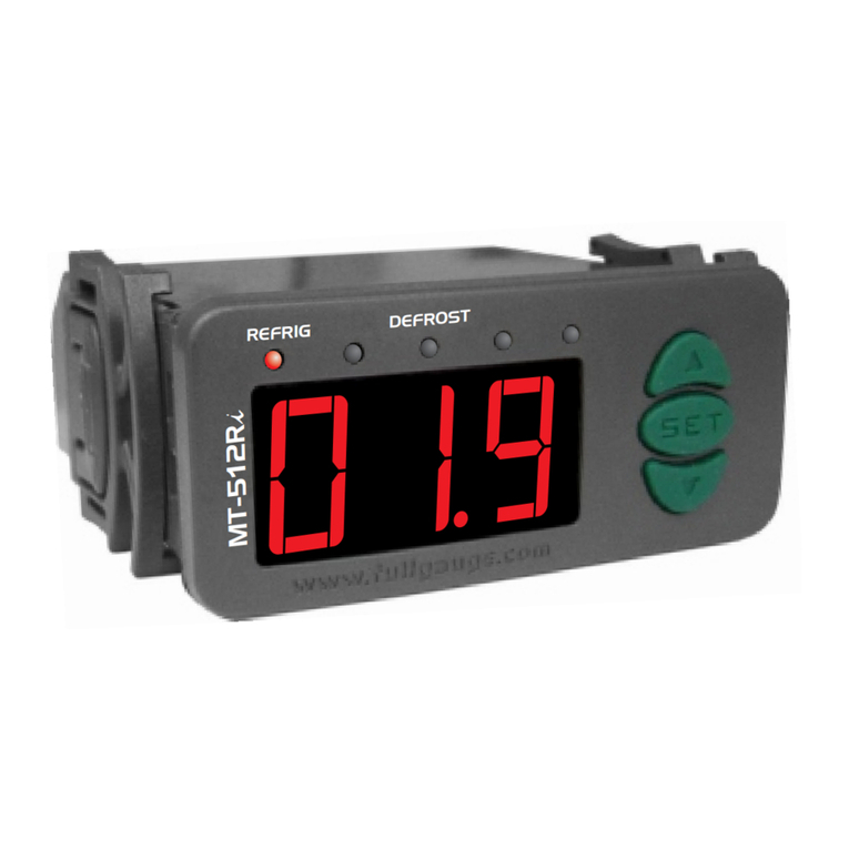
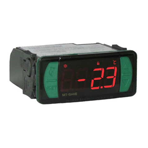
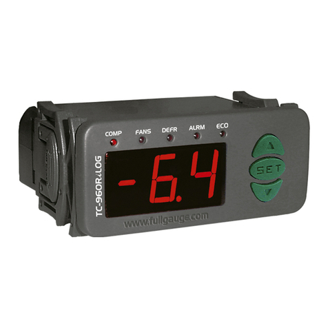
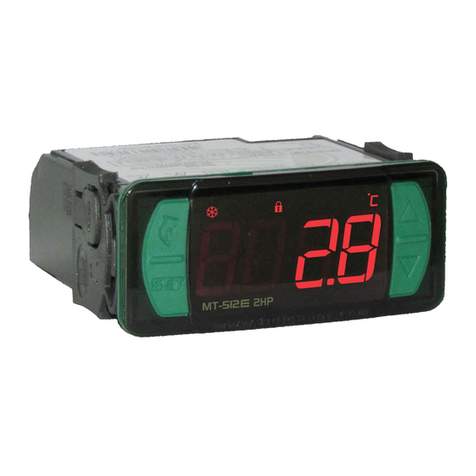
MT-516RVTi plus
TEMPERATURE CONTROLLER
WITH CYCLICAL TIMER AND VOLTAGE MONITOR
Ver. 06
MT516RVTI06-02T-10811
UL-Underwriters Laboratories
1.DESCRIPTION
2.APPLICATION
The integrates a heating or cooling thermostat with a cyclical timer and a
TrueRMSvoltagemonitor.ThroughtheF13andF14functionsispossibletodeterminethevoltagelimits
that the thermostat output can be active, this way protecting the compressor. Using True RMS*
technology the controller is capable of measuring the voltages in a variety of different situations in the
electricalgrid,thusprovidinggreaterprecisionintheprotectionofthecomponentsoftheapplication.
ProductcomplieswithULInc.(UnitedStatesandCanada).
•Milkcoolingtanks
•Chambersandcounters
•Heatpumps
MT-516RVTi plus
*TrueRMS:Istherealandeffectivevoltagevaluewhichalsoincludes thevoltagegeneratedbyhighfrequency
noisein thedistributing network(harmonic distortion).This isthe actualvoltage appliedto theconnected load
(example: electric motor, compressor). This method allows the precise voltage measurement for any type of
waveform.Othermeasurementmethodsgivecorrectvalueofappliedvoltageonlyforperfectsinewaveforms.
3.TECHNICALSPECIFICATION
4.CONFIGURATIONS
4.1-Controltemperatureadjust(SETPOINT)
-Electricpowersupply:
-Controltemperature:
-Maximumcurrent:
-Dimensions:
-Operatingtemperature:
-Operatinghumidity:
115or230Vac±10%(50/60Hz)
-50to105°C(decimalresolutionbetween-10and100ºC)
-58to221ºF
8(3)A/250Vac1/4HP(eachoutput)
71x28x71mm
0 to50°C/32to122°F
10to90%RH(withoutcondensation)
-Press fortwosecondsuntil appearsonthedisplay.
Theactualcontroltemperaturewillappear.
-Usethe and keys tochangethevalueandpress whenready.
SET
SET
DescriptionFun Access code: 123 (one hundred and twenty three)
Temperature indication offset
Thermostat operating mode
Minimum setpoint allowed for the end user
Maximum setpoint allowed for the end user
Control temperature differential (hysteresis)
Delay for turning the compressor on
Cyclical timer´s time base
Cyclical timer´s on time
Cyclical timer´s off time
Initial state of cyclical timer
Cyclical timer always on when the compressor is on
Minimum working voltage (protection)
Maximum working voltage (protection)
Voltage indication offset
Voltage confirmation delay
Display indication mode
Equipment address in the RS-485 network
(1)
(2)
(3)
(3)
(3)
(4)
F01
F02
F03
F04
F05
F06
F07
F08
F09
F10
F11
F12
F13
F14
F15
F16
F17
F18
-
0.0°C / 0°F
0-cooling
4.0°C / 39°F
5.0°C / 41°F
1.0°C / 2°F
180 sec.
1-min.
3 sec./min.
12 sec./min.
1-on
1-yes
195 Volts
260 Volts
0 Volts
10 sec.
0
1
-
-5.0°C / -9°F
0-cooling
-50°C / -58°F
-50°C / -58°F
0.1°C / 1°F
0 sec.
0-sec.
1 sec./min.
1 sec./min.
0-off
0-no
90 Volts
90 Volts
-50 Volts
1 sec.
0
1
-
5.0°C / 9°F
1-heating
105°C/221°F
105°C/221°F
20.0°C / 36°F
999 sec.
1-min.
999 sec./min.
999 sec./min.
1-on
1-yes
260 Volts
260 Volts
50 Volts
30 sec.
2
247
4.2 - Parameters table
Minimum Maximum Default
(1)
(3)
(4)
F02-Temperatureindicationoffset
F12-Cyclicaltimeralwaysonwhenthecompressorison:
F13/F14/F16-Operationofthevoltagemonitor
F17-Displayindicationmode
The F02 functions allows for the correction of any changes in the reading, resulting from a change in the sensor or
alteration of the length of the cable.
This function works for some applications, as for example, on cooling tanks for milk, where the timer commands the
agitator that must remain on while cooling is taking place.
If the value of the voltage exceeds the limits set in F13 and F14 the compressor will be automatically turned off after the
time set in function F16 has lapsed.
The led “VOLTS” will slowly blink along with the Indication of the grid voltage on the display.
In the event that the voltage returns to the limits established, the compressor will only be turned on again after the time
scheduled in the F16 function has ended.
To deactivate the voltage monitoring, all you have to do is adjust functions F13 and F14 to the same value.
Function F17 allows you to choose the measurement that will be displayed during normal operation:
Temperature
Voltage
Temperature and voltage
(2)
4.3-Selectionof theunit (°C/ °F)
4.4-Parametersalteration
In order to define the temperature unit that the instrument will operate, enter the access code “231” in
thefunction .Theindication willappear.Press or tochoosebetween or
andconfirmwith .Afterselectingtheunittheindication willappearandtheinstrument
willreturntothefunction .Wheneverthetemperatureunitismodified,theparameters shouldbe
reconfigured,sincetheywillassumethedefaultvalues.
- Access function F01 by pressing the and keys at the same time for 2 seconds. When the
message appearsreleasethekeysandwaitforthe indication.
-Pressthe buttontoaccessthefunctionanduse and toenterthecode123.Whenready
pressagainthe buttontoconfirmthecodeandquitthefunctionF01.
- Select other functions by pressing or . To access the desired function press the key
quickly.
-Adjustthe function`snewvaluewiththe and keysandpress tosaveandreturnto the
functionsmenu.
- To exit the functions menu and return to normal operation press the button until the message
appearsonthedisplay.
SET
SET
SET
SET
SET
SET
5.FUNCTIONSWITHFACILITATED ACCESS
5.1-Minimumandmaximum logs
5.2-CyclicaltimerOn/Off statuschange
5.3-Cyclicaltimevisualization
5.4-Temperature,voltageandfrequencyvisualization
Pressand releasethe key quickly.The indication will appearfollowedbytheminimumand
maximum logged voltages. Shortly after the last voltage the indication will be shown and the
minimumandmaximumtemperatureswillbedisplayed.
toresettheminimumandmaximumlogsjustkeeppressingthe keyduringthevisualization
ofthelogs.Themessage willappearindicatingthesuccessfulloperation.
Tochangetheoutputofthecyclicaltimerfrom"on"to"off"orviceversajustpressthe keyuntilthe
appearsonthedisplay.
To visualize the current status (on/off) time that has already lapsed on the cyclical timer press
quickly.
Toconsultthevoltageandfrequencyoftheelectricalgridwhenthecontrollerisconfiguredtodisplaythe
temperaturejustpush the keyquickly.The current voltagevalue will bedisplayed followed bythe
frequencyindication andit`svalue.
To visualize the temperature while the controller is displaying the voltage press the key like
explainedabove.
Note:
SET
SET
6.SIGNALLING
Iftheinstrumentshows onthedisplayitmeansthataparameterisoutofacceptablerangeandit
mustbecorrected.
THERM-
VOLTS(alwayson)-
VOLTS(blinkingslowly)-
VOLTS(blinkingquickly)-
TIMER-
Thermostatoutputactive;
Indicatesthevoltagevisualization;
Indicatesvoltageinoutrangecondition;
Indicatesanerroronthevoltagemeasurement;
Cyclicaltimeroutputactive.
-Sensordisconnectedortemperatureoutofthespecifiedrange.
72 mm
29 mm
7. WIRING DIAGRAM
Note: The length of the cable for the sensor may be increased by the user up to 200 meters, using
PP2x24AWGcable.Forimmersioninwaterusethermometricwell.
1245678910 11 12
3
THERM
TIMER
AB
VOLTMETER
COMMON
Load 1 Load 2
0115V 230V
RS-485 serial
communication
Sensor
6-7
6-8 115V
230V
MT-516RVTi plus
- Belt
-Agitator
- Water ’pump
- Contact
Load 1 Load 2
Power
supply Loads
supply
VOLTMETER:
Connect the borne 9 to borne 7, when
the instrument is supplied in 115Vac or
borne 9 to borne 8, when the instrument
is in 230Vac.supplied
- Cooler
- Heater
- Contact
- Solenoid
Dimension of the clipping
for setting of the instrument
in panel
