manuals.online logo
Brands
  1. Home
  2. •
  3. Brands
  4. •
  5. Full Gauge Controls
  6. •
  7. Temperature Controllers
  8. •
  9. Full Gauge Controls MT-519Ri User manual

Full Gauge Controls MT-519Ri User manual

Ver.01
DIGITAL TEMPERATURE
CONTROLLER WITH TWO
INDEPENDENT STAGES
MT-519Ri
MT519Ri01-01T-12493
MT-519Ri
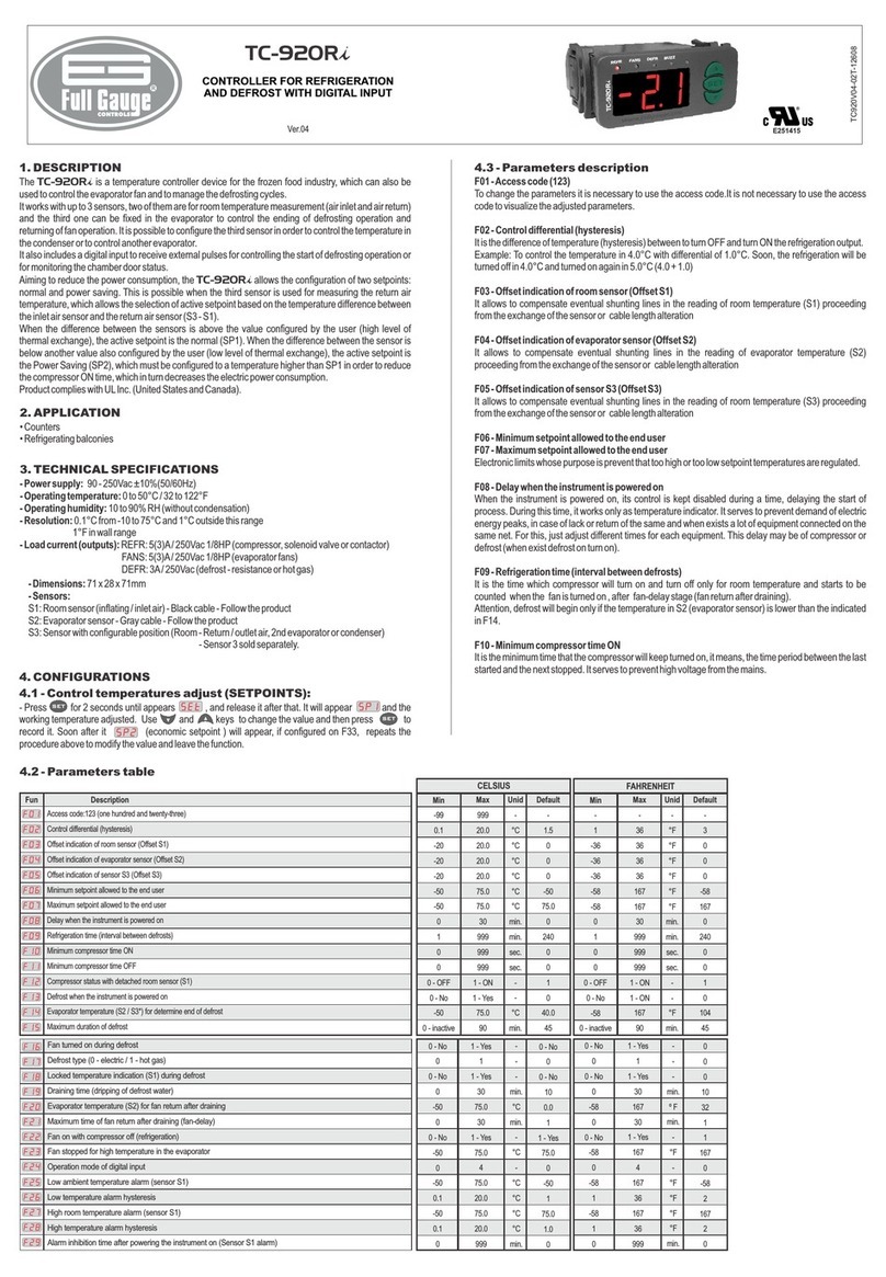
4.3 - Parameters table
CELSIUS FAHRENHEIT
Min MaxMax
Standard
UnitUnit
999
2
5.0
105
105
999
999
3
999
999
5.0
105
105
999
2
(*)
(*)
(*)
(*)
4
999
2
9
221
221
999
999
3
999
999
9
221
221
999
2
(*)
(*)
(*)
(*)
4
-
-
°C
°C
°C
sec
sec
-
s/m/h
s/m/h
°C
-
°C
°C
sec
-
-
-
°F
°F
°F
sec
sec
-
s/m/h
s/m/h
°F
-
°F
°F
sec
-
0
1
1.0
-50
0
0
0
1
1
0.0
0
-50
0
1
105
105
(*)
(*)
DescriptionFun
Access code: 123 (one hundred and twenty-three)
Thermostat 1 o
Hysteresis of thermostat 1
Minimum setpoint allowed to the user (thermostat 1)
Maximum setpoint allowed to the user (thermostat 1)
thermostat 1 output
hermostat 1 d
(thermostat 1)
C - Time off (thermostat 1)
C - Time on (thermostat 1)
Temperature sensor offset (thermostat 1)
Alarm display mode (thermostat 1)
Minimum value of the thermostat 1 alarm
Maximum value of the thermostat 1 alarm
Activation delay of thermostat 1 alarm
Thermostat 2 o
peration mode
Minimum time of turned off
T elay when the instrument is powered on
Cyclic timer operation mode
yclic timer
yclic timer
peration mode
-99
0
0.1
-50
-50
0
0
0
1
1
-5.0
0
-50
-50
0
0
-99
0
1
-58
-58
0
0
0
1
1
-9
0
-58
-58
0
0
Min
0
1
2
-58
0
0
0
1
1
0
0
-58
0
1
221
221
(*)
(*)
[F01]
[F02]
[F03]
[F04]
[F05]
[F06]
[F07]
[F08]
[F09]
[F10]
[F11]
[F12]
[F13]
[F14]
[F15]
[F16]
[F17]
[F18]
[F19]
[F20]
[F21]
[F22]
[F23]
[F24]
[F25]
[F26]
[F27]
[F28]
[F29]
[F30]
[F31]
[F32]
[F33]
0.1
-50
-50
0
0
0
0
0
-5.0
0
-50
-50
0
0
0
0
0
5.0
999
999
3
999
999
5.0
999
4
999
999
2
105
105
105
105
(*)
(*)
(*)
(*)
4
°C
°C
°C
-
s/m/h
s/m/h
°C
-
°C
°C
-
-
sec
sec
sec
sec
sec
1.0
-50
0
0
0
1
1
0.0
0
-50
0
0
0
0
0
105
105
(*)
(*)
Hysteresis of thermostat 2
Minimum setpoint allowed to the user (thermostat 2)
Maximum setpoint allowed to the user (thermostat 2)
thermostat 2 output
hermostat 2 d
(thermostat 2)
C - Time off (thermostat 2)
C - Time on (thermostat 2)
Temperature sensor offset (thermostat 2)
Alarm display mode (thermostat 2)
Minimum value of the thermostat 2 alarm
Maximum value of the thermostat 2 alarm
Activation delay of thermostat 2 alarm
Alarm output operation mode
Alarm output cyclic timer - Time off
Alarm output cyclic timer - Time on
Preferential display indication
Minimum time of turned off
T elay when the instrument is powered on
Cyclic timer operation mode
yclic timer
yclic timer
1
-58
-58
0
0
0
0
0
-9
0
-58
-58
0
0
0
0
0
9
999
999
3
999
999
9
999
4
999
999
2
221
221
221
221
(*)
(*)
(*)
(*)
4
°F
°F
°F
-
s/m/h
s/m/h
°F
-
°F
°F
-
-
sec
sec
sec
sec
sec
2
-58
0
0
0
1
1
0
0
-58
0
0
0
0
0
221
221
(*)
(*)
4.4 - Parameters description
[F01]
[F02]
[OFF] [F08]
[Ref]
[F03
[F08]
[F03]
[F08]
[F03]
- Access code (123)
- Thermostat 1 operation mode
- Thermostat OFF
- Thermostat in refrigeration mode -
Thermostat in heating mode -
- Hysteresis of thermostat 1
It is necessary to change the configuration parameters. To visualize the adjusted parameters, it is not
necessary to insert this access code.
Selects the operating mode of thermostat 1:
- In this mode, temperature sensor 1 can be disconnected. If is
configured as s, m or h, output will operate only as cyclic timer.
In this mode, output will be activated when
the temperature is above the value set in setpoint 1 plus the hysteresis ( ). When activated,
the output will be deactivated if the temperature drops below setpoint 1. If is configured as
s, m or h, output will cycle when the thermostat is refrigerating.
In this mode, output will be activated when the
temperature is below the value set in setpoint 1 minus the hysteresis ( ). When activated,
the output will be deactivated if the temperature rises above setpoint 1. If is configured as
s, m or h, output will cycle when the thermostat is heating.
It is the difference of temperature(hysteresis) between turn ON and turn OFF the output.
OUT1
OUT1
OUT1
OUT1
OUT1
OUT1
[F04]
[F05]
[F06]
[F08]
[F07]
[F08]
[OFF]
[,S,]
- Minimum setpoint allowed to the user (thermostat 1)
- Maximum setpoint allowed to the user (thermostat 1)
- Minimum time of thermostat 1 output turned off
- Thermostat 1 delay when the instrument is powered on
- Cyclic timer operation mode (thermostat 1)
- Cyclic timer disabled -
- Cyclic timer activated with time base in seconds
Electronic limits whose purpose is prevent that too high or too low setpoint temperatures are regulated.
It is the minimum time that the output will keep turned off, it means, the space of time between
the last stop ant the next start. If is configured as cyclic timer, this time will not be observed.
A delay that thermostat 1 will wait before activating its control functions. During this time only the
temperature is measured.
Allows configuring the cyclic timer associated to output .
Output will be constantly on or off depending only on the
temperature.
OUT1
OUT1
OUT1
[,M,]
[,H,]
[F09]
[F10]
[F11]
[F12]
[F30]
[OFF]
[,1,] [f13] [f14]
[,2,] [f13] [f14]
[,3,] [sp1] [f13] [sp1] [f14]
- Cyclic timer activated with time base in minutes
- Cyclic timer activated with time base in hours
- Cyclic timer - Time off (thermostat 1)
- Cyclic timer - Time on (thermostat 1)
- Temperature sensor offset (thermostat 1)
- Alarm display mode (thermostat 1)
For configurations in s, m or h (seconds, minutes or hours) output will keep cycling as
long as the temperature of the thermostat needs output to be activated.
The initial state of is always on
This function allows adjusting any deviation in the reading of sensor 1 caused by an increase (splice) in
the sensor cable or occasional replacement.
Selects how the thermostat 1 checks for the presence of an alarm. The activation of this function only
enables the alarm display. If the alarm output must also be enabled, function must be configured.
- Alarm off
- In-range alarm ( and )
- Out-range alarm ( and )
- In-range alarm relating to the setpoint ( - and + )
OUT1
OUT1
OUT1
Functions and are used when is configured as cyclic timer, observing the time
base configured in .
[F09] [F10]
[F08]
OUT1
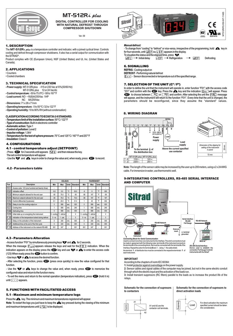
1 - DESCRIPTION
2 - APPLICATION
3 - TECHNICAL SPECIFICATIONS
MT519Ri
OUT1 OUT2
ALRM
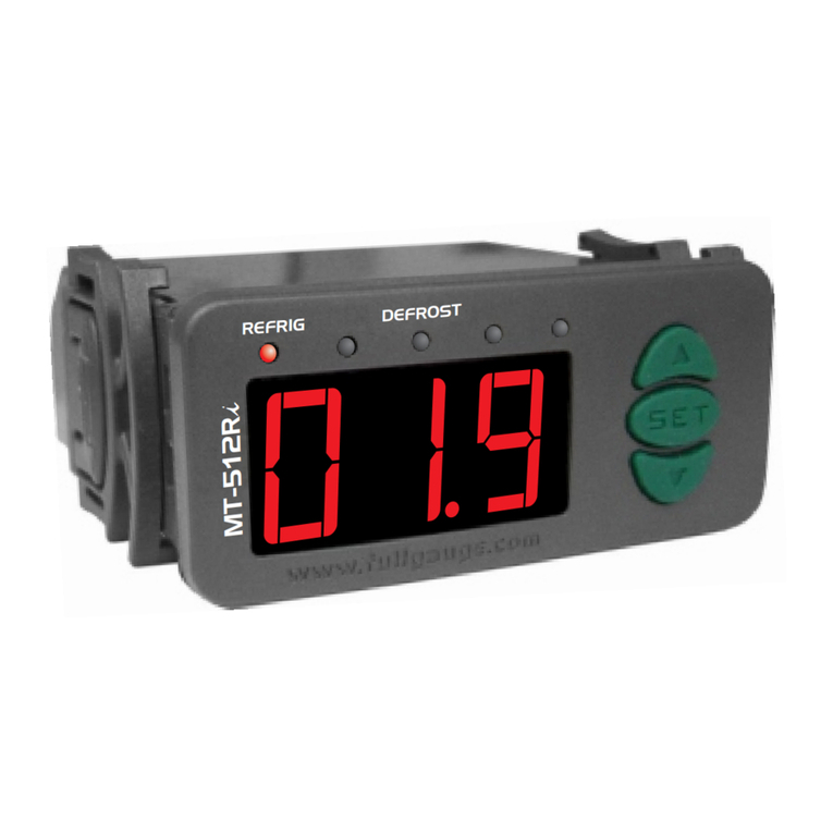
is a digital controller with two independent thermostats allowing functioning in two
different rooms. In addition, the two thermostat outputs can be configured as cyclic timers. One alarm
output can be linked to one of the thermostats.
• Boilers
• Ovens
• Heaters
• Freezers
• Chambers
• Hot/cold displays
MT-519Ri - 115 or 230 Vac ±10%(50/60 Hz)
MT-519RiL - 12 or 24 Vac/dc
NTC: -50 to 105°C(*) (with resolution of 0.1°C between -10 and 100°C and 1°C
in the rest of the range)
-58 to 221°F(*) (with resolution of 1°F in all range)
and : (NA) - 5(3)A/250Vac 1/8HP
(NF) - 3A/250Vac resistive load
71 x 28 x 71 mm
0 to 50 ºC / 32 to 122ºF
Power supply:
Control temperature:
- Maximum current per output:
- Dimensions:
- Operating temperature:
-
-
- Operating humidity: 10 to 90% RH (without condensation)
(*) This instrument can measure and control up to 200ºC (392°F) temperatures, since used with silicone
cable sensor (eg.: SB59).
- Press for 2 seconds until until appears, then release it. will appear(if enabled in
) and the adjusted temperature for the thermostat 1. Use the keys and to change the
value and, and then press again.
Set in the same way, the 2nd thermostat (if enabled in ).
- To access the function pressing simultaneously the keys and for 2 seconds until
appearing , releasing after that. Soon it will appear and then press (short touch).
- Use the keys and to enter with the access code (123) and, when ready, press to enter.
- Use the keys and to access the desired function.
- After selecting the function, press (short touch) to display the configured value for that function.
- Use the keys and to change the value and then press to record the new value and
return to the functions menu.
- To leave the functions menu and return to the normal operation, press until appear.
4 - CONFIGURATIONS
4.1 - Temperature adjust (SETPOINT)
Parameters alteration
@ [SET] [SP1]
[F02] > <
@
[F16]
[F01] > <
[Fun] [F01] @
>< @
><
@
>< @
@ [---]
4.2 -
[,4,] [sp1] [f13] [sp1] [f14]
[f13]
[f14]
[f12]
[f15]
[f07]
[F16]
[OFF] [F22]
[Ref]
[F17
[F22]
[F17]
[F22]
- Out-range alarm relating to the setpoint ( - and + )
These are the minimum and maximum values for the alarm to actuate if configured in .
The time that the alarm of thermostat 1 will remain off even in alarm conditions. This time is counted after
the time configured in has elapsed.
Selects the operating mode of thermostat 2:
- In this mode, temperature sensor 2 can be disconnected. If is
configured as s, m or h, output will operate only as cyclic timer.
In this mode, output will be activated when
the temperature is above the value set in setpoint 2 plus the hysteresis ( ). When activated,
the output will be deactivated if the temperature drops below setpoint 2. If is configured as
s, m or h, output will cycle when the thermostat is refrigerating.
In this mode, output will be activated when the
temperature is below the value set in setpoint 2 minus the hysteresis ( ). When activated,
the output will be deactivated if the temperature rises above setpoint 2. If is configured as
s, m or h, output will cycle when the thermostat is heating.
- Minimum value of the thermostat 1 alarm
- Maximum value of the thermostat 1 alarm
- Activation delay of thermostat 1 alarm
- Thermostat 2 operation mode
- Thermostat OFF
- Thermostat in refrigeration mode -
Thermostat in heating mode -
OUT2
OUT2
OUT2
OUT2
OUT2
(*) This parameter allows adjustments up to 200ºC (392°F) but to work on these conditions it has to be
used with silicone cable sensor (ex.: SB59).
Standard
OUT1 (NA)
C1
OUT1 (NA)
OUT2 (NA)
C2
ALRM (NF)
234567810 11 12
Above specified current use
a contactor.
1
Loads
supply
- Thermostat 2 output
C2
- Thermostat 1 output
C1
9
Sensor 1
Sensor 2
Power
supply
115 V
(12 V)
230 V
(24 V)
0
4-5
4-6
115V
230V
12V
24V
MT-519Ri MT-519RiL
- Alarm output
[f17]
[f18]
[f19]
[f20]
[F22]
[f21]
[f22]
[OFF]
[,S,]
[,M,]
- Hysteresis of thermostat 2
- Minimum setpoint allowed to the user (thermostat 2)
- Maximum setpoint allowed to the user (thermostat 2)
- Minimum time of thermostat 2 output turned off
- Thermostat 2 delay when the instrument is powered on
- cyclic timer operation mode (thermostat 2)
- Cyclic timer disabled -
- Cyclic timer activated with time base in seconds
- Cyclic timer activated with time base in minutes
It is the difference of temperature(hysteresis) between turn ON and turn OFF the output.
Electronic limits whose purpose is prevent that too high or too low setpoint temperatures are regulated.
It is the minimum time that the output will keep turned off, it means, the space of time between
the last stop ant the next start. If is configured as cyclic timer, this time will not be observed.
A delay that thermostat 2 will wait before activating its control functions. During this time only the
temperature is measured.
Allows configuring the cyclic timer associated to output .
Output will be constantly on or off depending only on
the temperature.
OUT2
OUT2
OUT2
OUT2
[,H,]
[F23]
[F24]
[F25]
[F26]
[F30]
[OFF]
[,1,] [F27] [F28]
[,2,] [F27] [F28]
[,3,] [SP2] [F27] [SP2] [F28]
[,4,] [SP2] [F27] [SP2] [F28]
- Cyclic timer activated with time base in hours
- cyclic timer - Time off (thermostat 2)
- cyclic timer - Time on (thermostat 2)
- Temperature sensor offset (thermostat 2)
- Alarm display mode (thermostat 2)
For configurations in s, m or h (seconds, minutes or hours) output will keep cycling as
long as the temperature of the thermostat needs output to be activated.
The initial state of is always on.
This function allows adjusting any deviation in the reading of sensor 2 caused by an increase (splice) in
the sensor cable or occasional replacement.
Selects how the thermostat 2 checks for the presence of an alarm. The activation of this function only
enables the alarm display. If the alarm output must also be enabled, function must be configured.
- Alarm off
- In-range alarm ( and )
- Out-range alarm ( and )
- In-range alarm relating to the setpoint ( - and + )
- Out-range alarm relating to the setpoint ( - and + )
OUT2
OUT2
OUT2
Functions and are used when is configured as cyclic timer, observing the time
base configured in .
[F22] [F24]
[F22]
OUT2
[f27]
[f28]
[f26]
[f29]
[f21]
[f30]
[Off]
[,1,]
[,2,]
[,3,]
[,4,]
[f31]
[f32]
[,0,]
- Minimum value of the thermostat 2 alarm
- Maximum value of the thermostat 2 alarm
- Activation delay of thermostat 2 alarm
- Alarm output operation mode
- Alarm output cyclic timer - Time off
- Alarm output cyclic timer - Time on
These are the minimum and maximum values for the alarm to actuate if configured in .
The time that the alarm of thermostat 2 will remain off even in alarm conditions. This time is counted after
the time configured in has elapsed.
Selects how the alarm output is activated
- Alarm output off
- The alarm output is activated when there is an alarm for thermostat 1
-The alarm output is activated when there is an alarm for thermostat 2
- The alarm output is activated when there is an alarm for thermostat 1 or 2
- The alarm output is activated when there is an alarm for thermostat 1 and 2 at the same
time.
Selects the cycling time of the alarm output when it is active. If one of these functions is set to , the
output will always be on.
[F33]
[t-1]
[t-2]
[all]
<
[F02] [F16] [OFF]
[F02] [F16] [OFF]
<
[rst]
- Preferential display indication
Selects how the temperatures are shown in the display.
- Thermostat 1
- Thermostat 2
- Alternating thermostats 1 and 2
Press , led will turn on showing the minimum temperature recorded. Soon after, the maximum
temperature recorded for thermostat 1 will be displayed. Then led will turn on and the respective
minimum and maximum temperatures recorded will be displayed. If any temperature is turned off
( or in ), the respective information will not be displayed. Caso alguma
temperatura estiver desligada ( ou em ), as respectivas informações não serão
mostradas.
Note: To reset the registers, keep the key pressed while the maximum and minimum temperatures
are displayed, until appears.
5
5.1 -
-FUNCTIONS WITH FACILITATED ACCESS
Register of minimum and maximum temperatures
T1
T2
5.2 Alarm inhibition
5.3 Viewing current
SIGNALING
-
- temperatures
6-
To disable the alarm, press and simultaneously. Only the output will be disabled. The
message will keep displaying. When disabled, the alarm will happen again after exiting the current alarm
condition and return to a new condition.
If function is configured as or , the other temperature can be displayed, i.e. upon
pressing and with function configured as temperature 2 will be displayed 2, and if
configured as temperature 1 will be displayed.
The temporary indication lasts 15 seconds.
- Temperature displayed at sensor 1;
- Temperature displayed at sensor 2;
- Thermostat 1 output on;
- Thermostat 2 output on;
-Alarm output on;
- Sensor 1 temperature;
- Sensor 2 temperature;
- Sensor 1 detached or temperature out the range;
- Sensor 2 detached or temperature out the range;
- Thermostat 1 extra-range upper alarm ;
<@
[F33] [t-1] [t-2]
> [F33] [t-1]
[t-2]
[t-1]
[t-2]
[Er1]
[Er2]
[A1H]
T1
T2
OUT1
OUT2
ALRM
[A1L]
[A1n]
[A2H]
[A2L]
[A2n]
[rst]
[SOF]
[CyC]
[PPP]
.
[FAC] [F01]
- Thermostat 1 extra-range lower alarm;
- Thermostat 1 intra-range alarm;
- Thermostat 2 extra-range upper alarm;
- Thermostat 2 extra-range lower alarm ;
- Thermostat 2 intra-range alarm;
- Indicates that the minimum and maximum values are being restarted;
- Indicates the device software version;
- Indicates that the chosen output is configured for “cyclic timer " mode.
- Invalid configuration parameters, in this situation the outputs will be turned off.
Check which parameter have invalid information and correct it to return to normal
operation.
The indic soon after the current temperature unit
message will appear, and the instrument will return to the function . Every
time that the unit is changed, the parameters should be reconfigured, since they assume the “standard”
values.
7-U
.
NIT SELECTION (ºC / ºF)
In o
After selecting
the unit the
rder to define the unit that the instrument will operate in, enter function with the access code
231 and confirm with the key. ation and
Press or to choose between or and confirm with the key
[F01]
@ [UNi]
> < [,=C] [,=F] @
Note: Sensor cable length can be increased by the user until 200 meters, using 4 x 0,20mm².
8-WIRING DIAGRAM
IMPORTANT
1:
2:
3:
According to the chapters of norm IEC 60364:
Install on the power supply
Sensor cables and signal cables of the computer may be joined, but not in the same electric conduit
through which the electric input and the activation of the loads run
Install transient suppresors (RC filters) parallel to the loads as to increase the product life of the
relays.
protector against overvoltage
Schematic for the connection of supresors
to contactors
A1 and A2 are the
contactor coil terminals.
Schematic for the connection of supresors to
direct activation loads
Load
Suppresor
For direct activation the maximum
specified current should be taken
into consideration.
A1
A2
Supresor
ENVIRONMENTAL INFORMATION
Package:
Products:
Disposal:
The packages material are 100% recyclable. Just dispose it through specialized
recyclers.
The electro components of Full Gauge controllers can be recycled or reused if it is
disassembled for specialized companies.
Do not burn or throw in domestic garbage the controllers which have reached the end-of-
life. Observe the respectively law in your region concerning the environmental
responsible manner of dispose its devices. In case of any doubts, contact Full Gauge
controls for assistance.
PROTECTIVE :VINYL
This adhesive vinyl (included inside the packing) protects the instruments against
water drippings, as in commercial refrigerators, for example. Do the application after
finishing the electrical connections.
Remove the protective paper
and apply the vinyl on the entire
superior part of the device,
folding the flaps as indicated by
the arrows.
72 mm
Dimension of the clipping
for setting of the instrument
in panel
29 mm

Other Full Gauge Controls Temperature Controllers manuals

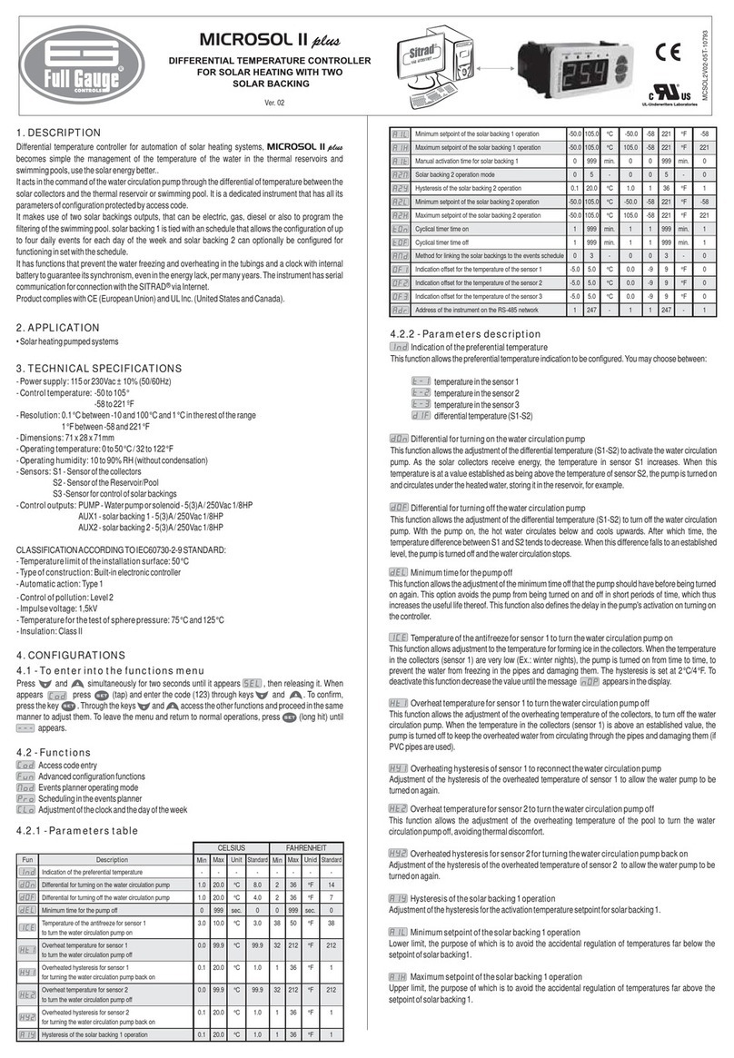
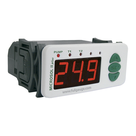
Full Gauge Controls MICROSOL II plus User manual

Full Gauge Controls

Full Gauge Controls MICROSOL II plus User manual

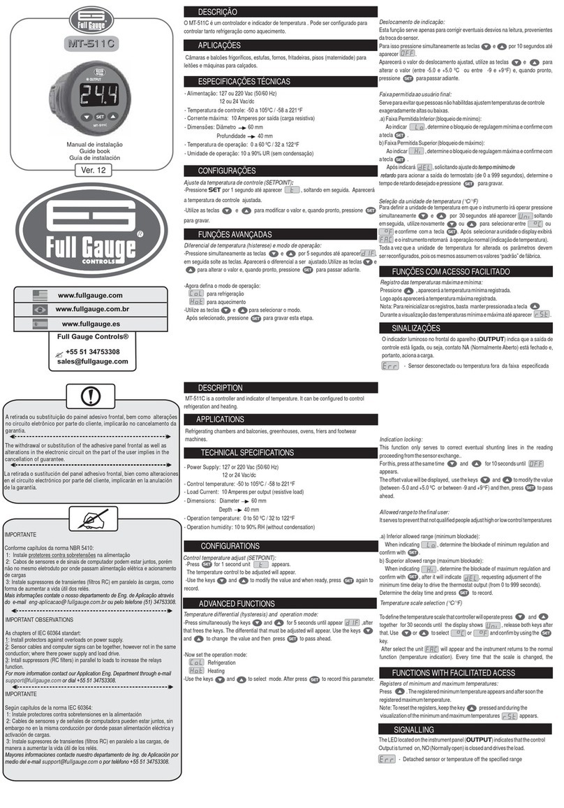
Full Gauge Controls MT-511C Manual

Full Gauge Controls

Full Gauge Controls MT-511C Manual

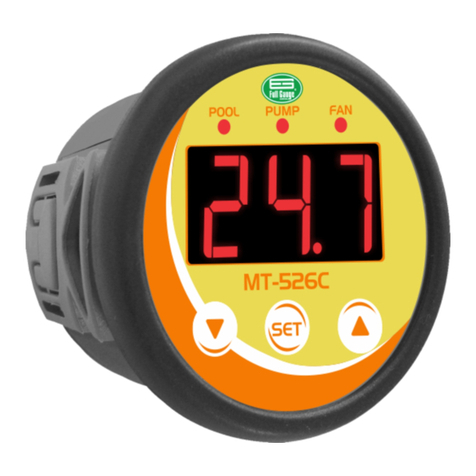
Full Gauge Controls MT-526C User manual

Full Gauge Controls

Full Gauge Controls MT-526C User manual

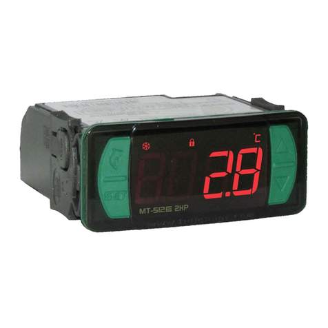
Full Gauge Controls MT-512E 2HP User manual

Full Gauge Controls

Full Gauge Controls MT-512E 2HP User manual

Full Gauge Controls MT-512Ri plus User manual

Full Gauge Controls

Full Gauge Controls MT-512Ri plus User manual

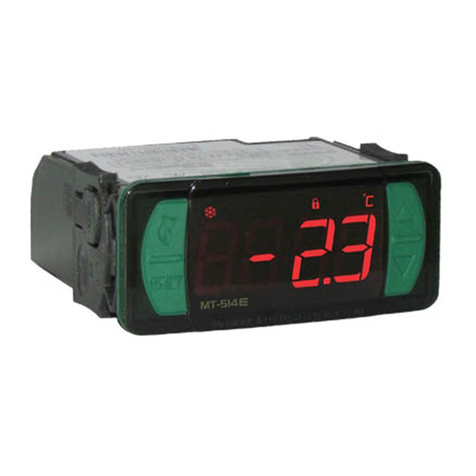
Full Gauge Controls Evolution MT-514 E User manual

Full Gauge Controls

Full Gauge Controls Evolution MT-514 E User manual

Full Gauge Controls TC-960Ri LOG User manual

Full Gauge Controls

Full Gauge Controls TC-960Ri LOG User manual

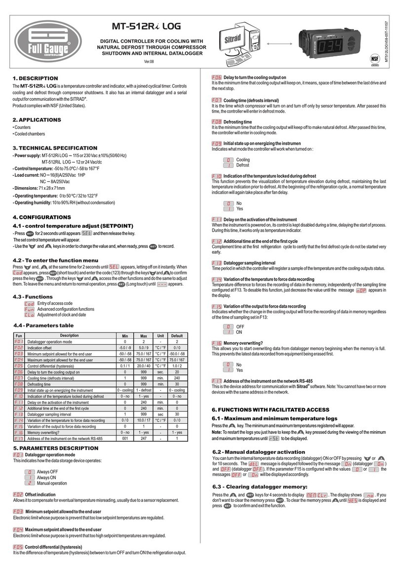
Full Gauge Controls MT-512Ri LOG User manual

Full Gauge Controls

Full Gauge Controls MT-512Ri LOG User manual

Full Gauge Controls MT-512Ri LOG User manual

Full Gauge Controls

Full Gauge Controls MT-512Ri LOG User manual

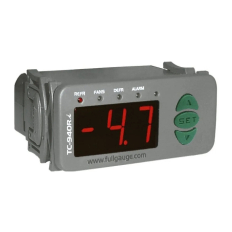
Full Gauge Controls TC-940Ri plus User manual

Full Gauge Controls

Full Gauge Controls TC-940Ri plus User manual

Full Gauge Controls MT-516RVTi plus User manual

Full Gauge Controls

Full Gauge Controls MT-516RVTi plus User manual

Full Gauge Controls TC-940Ri plus User manual

Full Gauge Controls

Full Gauge Controls TC-940Ri plus User manual

Full Gauge Controls MICROSOL II plus User manual

Full Gauge Controls

Full Gauge Controls MICROSOL II plus User manual

Full Gauge Controls MT-512Ri LOG User manual

Full Gauge Controls

Full Gauge Controls MT-512Ri LOG User manual

Full Gauge Controls TC-940Ri Plus User manual

Full Gauge Controls

Full Gauge Controls TC-940Ri Plus User manual

Full Gauge Controls TC-920Ri User manual

Full Gauge Controls

Full Gauge Controls TC-920Ri User manual

Full Gauge Controls TC-940Ri User manual

Full Gauge Controls

Full Gauge Controls TC-940Ri User manual

Popular Temperature Controllers manuals by other brands

Carel WS00W02M Series manual

Carel

Carel WS00W02M Series manual

AEG RTF-A Operation and installation

AEG

AEG RTF-A Operation and installation

Sentry Xpress 5.0 Instructions for use

Sentry

Sentry Xpress 5.0 Instructions for use

Golander GL102B user guide

Golander

Golander GL102B user guide

Smart Controller MyTemp user manual

Smart Controller

Smart Controller MyTemp user manual

Franke ZAQUA020 Installation and operating instructions

Franke

Franke ZAQUA020 Installation and operating instructions

Yudian AI-218 Operation manual

Yudian

Yudian AI-218 Operation manual

Distech Allure EC-Smart-Vue Series Hardware installation guide

Distech

Distech Allure EC-Smart-Vue Series Hardware installation guide

elsner elektronik KNX eTR 201 Sunblind quick start guide

elsner elektronik

elsner elektronik KNX eTR 201 Sunblind quick start guide

EVE aqua 10EAI8101 Get started

EVE

EVE aqua 10EAI8101 Get started

ETC Echoflex RTS Series installation guide

ETC

ETC Echoflex RTS Series installation guide

Newport ILX Lightwave LDT-5910C user manual

Newport

Newport ILX Lightwave LDT-5910C user manual

Philio PAT14 quick start guide

Philio

Philio PAT14 quick start guide

Solo SL4848 Series quick start guide

Solo

Solo SL4848 Series quick start guide

Omega CN1000-RTD quick start

Omega

Omega CN1000-RTD quick start

Siemens RDJ10RF/SET manual

Siemens

Siemens RDJ10RF/SET manual

MAV Sense T125ID user manual

MAV Sense

MAV Sense T125ID user manual

Viessmann VITOTROL 100 operating instructions

Viessmann

Viessmann VITOTROL 100 operating instructions

manuals.online logo
manuals.online logoBrands
  • About & Mission
  • Contact us
  • Privacy Policy
  • Terms and Conditions

Copyright 2025 Manuals.Online. All Rights Reserved.