manuals.online logo
Brands
  1. Home
  2. •
  3. Brands
  4. •
  5. FUTABA
  6. •
  7. Controllers
  8. •
  9. FUTABA MC401CR Sport Edition User manual

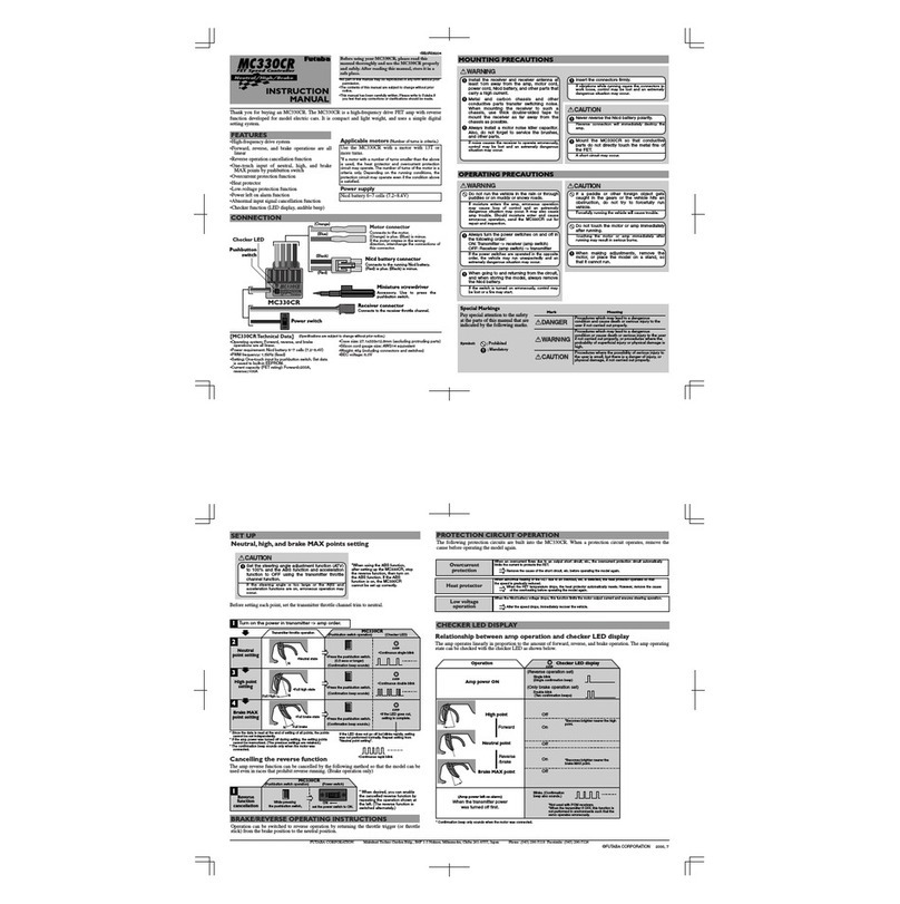
FUTABA MC401CR Sport Edition User manual

MOUNTING PRECAUTIONS
Accessories
s#APACITORSFORMOTOR
s4IESTRAP
s$OUBLESIDEDTAPE
s-INIATURESCREWDRIVER
5SETOPRESSTHEPUSHBUTTONSWITCH
)NSTALL THE RECEIVER AND RECEIVER ANTENNA AWAY FROM THE
AMPMOTORCORDPOWERCORD.ICDBATTERYANDOTHERPARTS
THATCARRYAHIGHCURRENT
-ETAL AND CARBON CHASSIS AND OTHER CONDUCTIVE PARTS
TRANSFER SWITCHING NOISE 7HEN MOUNTING THE RECEIVER TO
SUCH A CHASSIS USE THICK DOUBLESIDED TAPE TO MOUNT THE
RECEIVERASFARAWAYFROMTHECHASSISASPOSSIBLE
!LWAYSINSTALLAMOTORNOISESUPPRESSERCAPACITOR!LSODO
NOTFORGETTOSERVICETHEBRUSHESANDOTHERPARTS
)F NOISE CAUSES THE RECEIVER TO OPERATE ERRONEOUSLY CONTROL MAY BE
LOSTANDANEXTREMELYDANGEROUSSITUATIONMAYOCCUR
)NSERTTHECONNECTORSFIRMLY
)FVIBRATIONSWHILERUNNINGCAUSETHECONNECTORSTOWORKLOOSECONTROL
MAYBELOSTANDANEXTREMELYDANGEROUSSITUATIONMAYOCCUR
$ONOTRUNTHEVEHICLEINTHERAINORTHROUGHPUDDLESORONMUDDY
ORSNOWYROADS
)F MOISTURE ENTERS THE AMP ERRONEOUS OPERATION MAY CAUSE LOSS OF
CONTROLAND AN EXTREMELYDANGEROUS SITUATIONMAYOCCUR )T MAYALSO
CAUSE AMP TROUBLE 3HOULD MOISTURE ENTER AND CAUSE ERRONEOUS
OPERATIONSENDTHE-##2OUTFORREPAIRANDINSPECTION
!LWAYSTURNTHEPOWERSWITCHESONANDOFFINTHEFOLLOWINGORDER
/.4RANSMITTERRECEIVERAMPSWITCH
/&&2ECEIVERAMPSWITCHTRANSMITTER
)FTHE POWERSWITCHESARE OPERATED INTHEOPPOSITE ORDER THEVEHICLE
MAY RUN UNEXPECTEDLY AND AN EXTREMELY DANGEROUS SITUATION MAY
OCCUR
7HEN GOING TO AND RETURNING FROM THE CIRCUIT AND WHEN
STORINGTHEMODELALWAYSREMOVETHE.ICDBATTERY
)FTHESWITCHISTURNEDONERRONEOUSLYCONTROLMAYBELOSTORAFIREMAY
START
!LWAYSPERFORMACHECKOFOPERATIONBEFORERUNNING
7HEN MAKING ADJUSTMENTS REMOVE THE MOTOR OR PLACE THE
VEHICLEONASTANDSOTHATITCANNOTRUN
7HENNOTSETUPCORRECTLYTHEVEHICLEMAYRUN UNEXPECTEDLYANDAN
EXTREMELYDANGEROUSSITUATIONMAYOCCUR
MC401CR
INSTRUCTION
MANUAL
-.
Serial communication function (Options)
The following settings and operations are possible with a Windows PC by using the optional interface unit (CIU-2).
*Windows is registered trademark of Microsoft Corporation.
"EFORE USING YOUR -##2 PLEASE READ THIS MANUAL
THOROUGHLY AND USE THE -##2 PROPERLY AND SAFELY !FTER
READINGTHISMANUALSTOREITINASAFEPLACE
s.O PART OF THIS MANUAL MAY BE REPRODUCED IN ANY FORM
WITHOUTPRIORPERMISSION
s4HECONTENTS OFTHISMANUALARESUBJECTTOCHANGEWITHOUT
PRIORNOTICE
s4HIS MANUAL HAS BEEN CAREFULLY WRITTEN 0LEASE WRITE TO
&UTABA IF YOU FEEL THAT ANY CORRECTIONS OR CLARIFICATIONS
SHOULDBEMADE
Thank you for purchasing an MC401CR . The MC401CR is a high-frequency drive FET speed control developed for
model electric cars. It is compact and light weight competition speed control, and uses a simple digital setting system.
Applicable motors .UMBEROFTURNSISCRITERIA
Use the MC401CR with a motor with 10 turns or more.
*If a motor with a number of turns smaller than the
above is used, the heat protector and overcurrent
protection circuit may operate. The number of turns of
the motor is a criteria only. Depending on the running
conditions, the protection circuit may operate even if
the condition above is satisfied.
*The internal circuit of MC401CR is OK up to 10-turn
motors. On the other hand, the connectors for battery
and motor are general type that is often found at the
dealers. Therefore, to use high output power motor or
apply heavy load may result in overheating of the
connector section and melting the connection. If this
happen the connection will stick together. Please pay
special attention to avoid this matter.
Power supply
Nicd, NiMH battery 4~6 cells
(4.8~7.2V)
FEATURES
• SMD MOSFETs with smallest internal resistance for
minimal losses and maximum power
• Forward, reverse, and brake operations are all linear
• Reverse operation cancellation function
• PWM frequency is Performed by load adaptive
• Heat protector
• Low-voltage protection function
•
Fuse 30A (Buttery reverse plotection / Overload plotection)
• Power left on alarm function
•
Serial communication function
INSTALLATION TIPS
s-OUNTTHESPEEDCONTROLINTHEMODELUSINGTHEDOUBLESIDEDFOAMTAPESUPPLIED
s 0ROVIDE PLENTY OF COOLING OPENINGS IN THE BODYWORK THIS INCREASES THE PERFORMANCE AND EXTENDS THE LIFE OF ALL
lectronic components.
s)NSTALLTHESPEEDCONTROLINALOCATIONWHEREITISPROTECTEDFROMCRASHDAMAGE
s4HESPEEDCONTROLSHOULDBEINSTALLEDINSUCHAWAYTHATYOUHAVEEASYACCESSTOALLCONNECTORSANDTHESETUPBUTTON
Important:
s%NSURETHATTHEREISANADEQUATEDISTANCEAPPROXCMBETWEENTHESPEEDCONTROLANDPOWERCABLESANDTHERECEIVERORRECEIVERANTENNA!VOID
direct contact between all power system components and the receiver or antenna, as this can cause interference. If you encounter interference
problems, re-position the components in the model.
s4HEANTENNASHOULDBERUNVERTICALLYUPANDAWAYFROMTHERECEIVER!VOID CONTACT WITH ANYPARTSMADEOFCARBONFIBREORMETAL3EEALSOTHE
instructions supplied with your radio control system.
[MC401CR Technical Data] 3PECIFICATIONSARESUBJECTTOCHANGEWITHOUTPRIORNOTICE
s/PERATINGSYSTEM&ORWARDANDBRAKERESOLUTION
s0OWERREQUIREMENT.ICD.I-(BATTERY^CELLS^6
s07-FREQUENCY
Forward:100Hz〜10kHz/Initial value:K(Z〜K(Z
Brake:2.0kHz
s"%#VOLTAGE6EXCLUDINGATLESSTHAN6
s3ETTING/NETOUCHINPUTBYPUSHBUTTONSWITCH
s#URRENTCAPACITY&%4RATING
Forward :!-OMENTARYLOAD!
Reverse :!
s&USE!"UTTERYREVERSEPLOTECTION/VERLOADPLOTECTION
s#ASESIZEXXMMEXCLUDINGPROTRUDINGPARTS
s3ILICONCORDGAUGESIZE!7'EQUIVALENT
s7EIGHTGEXCLUDINGCONNECTORCORDSANDSWITCH
$ONOTWRAPYOUR-##2INFOIL
)TISIMPORTANTTOPROVIDEAFREEFLOWOFCOOLINGAIROVERIT
$ONOTREMOVETHECASEOF
-#
#2
4HE-##2MAYNOTBEREPAIRABLE
.EVERREVERSETHEBATTERYPOLARITY
2EVERSECONNECTIONWILLIMMEDIATELYDESTROYTHEAMP
-OUNT THE
-#
#2 SO THAT CONDUCTIVE PARTS DO NOT DIRECTLY
TOUCHTHESOLDERPARTSOFTHEINPUTOUTPUTCORD
!SHORTCIRCUITMAYOCCUR
)FAPEDDLEOROTHERFOREIGNOBJECTGETSCAUGHTINTHEGEARS
ORTHEVEHICLEHITSANOBSTRUCTIONDONOTTRYTOFORCEFULLYRUN
VEHICLE
&ORCEFULLYRUNNINGTHEVEHICLEWILLCAUSETROUBLE
$O NOT TOUCH THE MOTOR OR -##2 IMMEDIATELY AFTER
RUNNING
4OUCHING THE MOTOR OR AMP IMMEDIATELY AFTER RUNNING MAY RESULT IN
SERIOUSBURNS
)FTHEMOTORISCONNECTEDTOTHESPEEDCONTROLYOUMUSTNOT
RUNTHEMOTORBYCONNECTINGASEPARATEBATTERY
4HISWILLWRECKTHEUNIT
4URNTHEPOWERSWITCHESONINTHESTATEWHERETHEVEHICLEIS
FLOATED
7HEN TURNNING ON DEPENDING ON THE RECEIVER USED A MOTOR MAY
ROTATEFORAMOMENT"ECAREFULNOTTOINJUREAFINGERETCBYROTATIONOF
THEWHEELS
MOUNTING PRECAUTIONS
Special Markings
Pay special attention to the
safety at the parts of this
manual that are indicated by
the following marks.
Mark Meaning
0ROCEDURES WHICH MAY LEAD TO A DANGEROUS CONDITION AND CAUSE DEATH OR SERIOUS INJURY TO THE
USERIFNOTCARRIEDOUTPROPERLY
0ROCEDURESWHICHMAYLEADTOADANGEROUSCONDITIONORCAUSEDEATHORSERIOUSINJURYTOTHEUSER
IF NOT CARRIED OUT PROPERLY OR PROCEDURES WHERE THE PROBABILITY OF SUPERFICIAL INJURY OR PHYSICAL
DAMAGEISHIGH
0ROCEDURES WHERE THE POSSIBILITY OF SERIOUS INJURY TO THE USER IS SMALL BUT THERE IS A DANGER OF
INJURYORPHYSICALDAMAGEIFNOTCARRIEDOUTPROPERLY
Symbol: 0ROHIBITED
-ANDATORY
sData logging function data read and erase (Data logging memorizes the running current and power supply voltage for
APPROXIMATELYMINUTESATSECONDINTERVALS
s6ARIABLEFREQUENCYRANGESETTING(Z^K(Z3ETSTHELOADRESPONSESYSTEMVARIABLEFREQUENCYRANGE$EAD
BANDS^S4HENEUTRALPOINTRANGECANBESET
s,OWBATTERYPROTECTIONVOLTAGESETTING6^63ETSTHEvoltage which cuts output to motor when the power supply
voltage is drops.)
s#URRENTLIMITER!^!CANCEL4HECURRENTLIMITFORSUPPRESSINGWASTEDPOWERCANALSOBESETANDTURNED/&&
s"RAKE-!8DUTY^3ETSTHEBRAKESTRENGTHOFTHE-!8BRAKEPOINTFROMNEUTRAL
s.EUTRALBRAKE^"RAKESETTINGATTHETHROTTLENEUTRALPOINT
s2EVERSECANCELROBOT
Forward
neutral
reverse
)
N
N
N
CONNECTION LED DISPLAY
In set-up mode MC401CR stores every step when you press the Set-up button. All the settings are stored in the unit even when the
speed control is subsequently disconnected from the battery. Set up the following basic functions on your transmitter (if present):
s(IGH!46%0!THROTTLETRAVELMAXIMUM,OW!46%0!!4,BRAKETRAVELMAXIMUM
s%80%80/EXPONENTIALSTARTWITH
s35"TRIMNEUTRALTRIMCENTER4(TRIMCENTER
s4HROTTLEREVERSESERVOREVERSEANYSETTINGMUSTNOTBECHANGEDAFTERCOMPLETIONOFSETUPPROCEDURE
s!SYMMETRICALSTICKTRAVELISPOSSIBLETHROTTLEBRAKE
)FYOURTRANSMITTERDOESNOTFEATURETHESESETUPFUNCTIONSITISALREADYINhBASICSETUPvMODE
2EMOVETHEMOTORPINIONORENSUREINSOMEOTHERWAYTHATTHEWHEELSOFTHEMODELAREFREETOROTATE
sSwitch the transmitter on.
s3ETTHETRANSMITTERTHROTTLESTICKTONEUTRALANDTHENSWITCHTHESPEEDCONTROLON
*
$EPENDINGONTHENEUTRALPOSITIONOFTHETHROTTLESTICKTHEREDANDGREEN,%$WILLBLINKSIMULTANEOUSLYORANGEANDABEEPINGSOUNDWILLBEREPEATED
(Alarm: Waiting for neutral data)
Turn on the power in following order.
s4HE3%4,%$FLASHESGREENTOINDICATETHATTHEUNITISINSETUPMODE
s4HISCOMPLETESTHESETUPPROCEDURE
Hold the SET button pressed in for at least 3 seconds using the small screwdriver supplied.
©FUTABA CORPORATION
2007,11 ①
MC401CR
Protection Circuits
Heat protection: !FTER&%4OVERHEATINGISDETECTEDTHEOUTPUTTOTHEMOTORISGRADUALLYLOWEREDANDWHENDEGRESSISREACHED
APROTECTIONCIRCUITOPERATIONALARMISACTIVATEDANDOUTPUTTOTHEMOTORISCUT4HEPROTECTIONCIRCUITISAUTOMATICALLYRESETBYADROPIN
THE&%4TEMPERATURE
Low battery protection: 7HENTHEPOWERSUPPLYVOLTAGEDROPSTHEOUTPUTCURRENTTOTHEMOTORISLIMITEDANDSUPPLYVOLTAGETOTHE
RECEIVERISENSURED7HENTHEPOWERSUPPLYVOLTAGEDROPSTOTHESETVOLTAGEINITIALSETTING6APROTECTIONCIRCUITOPERATIONALARM
ISACTIVATEDANDOUTPUTTOTHEMOTORISCUT4HEPROTECTIONCIRCUITISAUTOMATICALLYRESETBYRECOVERYOFTHEPOWERSUPPLYVOLTAGE
Reverse Cancelling function (Brake operation only)
7HILEPRESSINGTHEPUSHBUTTONSWITCHSETTHEPOWERSWITCHTO/.FLASHESORANGEANDTHEMOTORBEEPSTIMES
7HENDESIREDYOUCANENABLETHECANCELLEDREVERSEFUNCTIONBYREPEATINGTHEOPERATIONSHOWNABOVE4HEREVERSEFUNCTIONISSWITCHEDALTERNATELY
The reverse mode by LED can check.
3ETTHEPOWERSWITCHTO/.FLASHES,%$
SET button operation LED
Neutral
point
setting
High
point
setting
Brake MAX
point
setting
sNeutral state
s4HE-##2OPERATINGSTATECANBECHECKEDWITHTHE,%$ASSHOWNBELOW
s!FTEROPERATINGTHETHROTTLETRIGGERSTICKOFATRANSMITTERTOTHEBRAKEREVERSESIDEIFITISAGAINOPERATEDTOTHEBRAKESIDE
ONCEITRETURNSTOANEUTRALPOSITION-##2WILLCARRYOUTREVERSEOPERATION
flashes red and the motor beeps.
*Not used with PCM receivers.
*When the transmitter if OFF, this function is not performed in environments such
that the servo operates erroneously
On (red)
High
point
On (green)
Brake MAX
point Brake or Reverse
Brake
Reverse
On (red)
*Becomes brighter nearer the
MAX point.
On (orange)
*Becomes brighter nearer the
MAX point.
Foward
On (green)
*Becomes brighter nearer the high
point.
LED
LED
LED
MODE
4HECONFIRMATIONBEEPSOUNDSONLYWHENTHEMOTORWASCONNECTED
SET UP
sFull brake
state
sFull high
state
s
Press SET button
once.
s
Press SET button
once.
s
Press SET button
once.
LED goes out and the
motor beeps.
flashes green two times
and the motor beeps.
LED goes out
flashes orange and the motor beeps.
flashes orange
flashes red and the motor beeps.
flashes green three times
and the motor beeps.
LED goes out
* Since the data is read at the end of setting
of all points, the points cannot be set
independently.
* If the amp power was turned off during
setting, the setting points cannot be
memorized. (The previous settings are
retained.)
* The confirmation beep sounds only when
the motor was connected.
* If you make a mistake during the set-up
procedure, an setting is not completed.:
switch MC401CR off and start again from
the first step.
* Check the operation by the following "LED
DISPLAY." When throttle operation and
the CHECKER LED DISPLAY are not
correct, set up again from the first step.
(Amp power left on alarm)
When the transmitter power
was turned off first.
Off
Neutral
point
*at Neutral Brake:
On (green or red)
*When the switch of speed control is turned ON ahead of a
transmitter.
*When the neutral position of a transmitter differs from the last setup.
(Alarm when waiting for the data of a neutral point)
Operation
Cause
(Protection circuit operation)
When a protection circuit operates.
(
Data error alarm
)
Displayed when an abnormal signal was input.
Transmitter throttle
operation
3
4
5
1
2
&54!"!#/20/2!4)/.-AKUHARI4ECHNO'ARDEN"LDG"&.AKASE-IHAMAKU#HIBA*APAN0HONE&ACSIMILE
Silicone flex wire Orange
Silicone flex wire Red
Silicone flex wire Blue
Silicone flex wireBlack
Fuse
Motor connector
Connects to the motor.
(Orange) is plus. (Blue) is minus.
If the motor rotates in the wrong direction,
interchange the connections of this connector.
Nicd battery connector
Connects to the running Nicd battery.
(Red) is plus. (Black) is minus.
Receiver connector
Connects to the receiver throttle channel (CH2).
Power switch
Pushbutton switch
LED
Terminal cover
-OTORSWITHNOSUPPRESSORCAPACITORSORINADEQUATESUPPRESSIONMAYCAUSETHE-##2
to malfunction. Always solder the capacitors supplied to your motor.
*
#AUTIONNEVERUSE3CHOTTKYDIODESINCONJUNCTIONWITHAFORWARDREVERSESPEEDCONTROL
such as the MC401CR.
Solder the suppressor capacitors and the Schottky diode to the motor.
Suppressor
capacitors
The mode to reverse
The mode to cancel reverse The mode to robot
flashes red twice flashes green 3 timesflashes orange once

Other FUTABA Controllers manuals

FUTABA MC330R User manual

FUTABA

FUTABA MC330R User manual

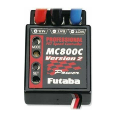
FUTABA MC800C User manual

FUTABA

FUTABA MC800C User manual

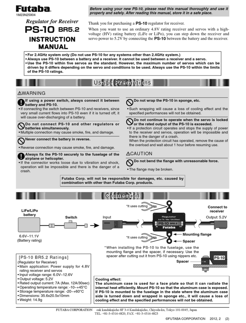
FUTABA PS-10 BR5.2 User manual

FUTABA

FUTABA PS-10 BR5.2 User manual

FUTABA T16IZ Installation instructions

FUTABA

FUTABA T16IZ Installation instructions

FUTABA MC800C Ver.2 User manual

FUTABA

FUTABA MC800C Ver.2 User manual

FUTABA MCP-2 User manual

FUTABA

FUTABA MCP-2 User manual

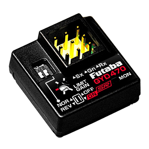
FUTABA GYD 470 User manual

FUTABA

FUTABA GYD 470 User manual

FUTABA WSC-1 User manual

FUTABA

FUTABA WSC-1 User manual

FUTABA S5801 User manual

FUTABA

FUTABA S5801 User manual

FUTABA GYC440 User manual

FUTABA

FUTABA GYC440 User manual

FUTABA MC850C High Power Edition User manual

FUTABA

FUTABA MC850C High Power Edition User manual

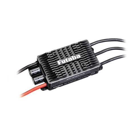
FUTABA MC9100A User manual

FUTABA

FUTABA MC9100A User manual

FUTABA T18SZ Technical manual

FUTABA

FUTABA T18SZ Technical manual

FUTABA FP-3PB User manual

FUTABA

FUTABA FP-3PB User manual

FUTABA PK-FSM-2.4G User manual

FUTABA

FUTABA PK-FSM-2.4G User manual

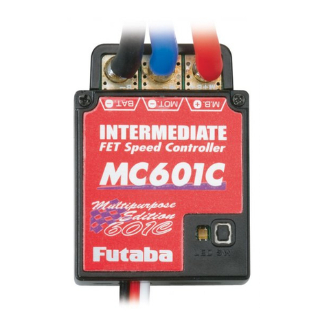
FUTABA MC601C Multipurpose Edition User manual

FUTABA

FUTABA MC601C Multipurpose Edition User manual

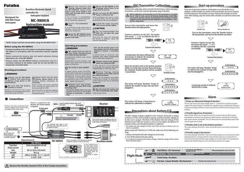
FUTABA MC-980H User manual

FUTABA

FUTABA MC-980H User manual

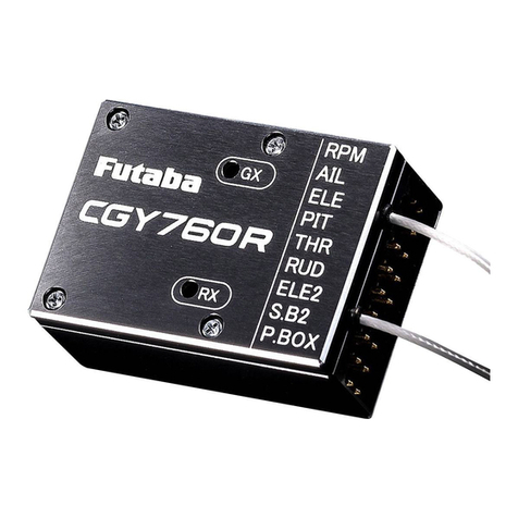
FUTABA CGY760R User manual

FUTABA

FUTABA CGY760R User manual

FUTABA MC950CR High Power Edition User manual

FUTABA

FUTABA MC950CR High Power Edition User manual

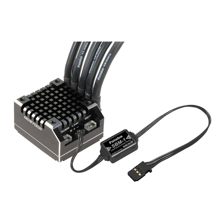
FUTABA MC970CR User manual

FUTABA

FUTABA MC970CR User manual

FUTABA CGY750 User manual

FUTABA

FUTABA CGY750 User manual

FUTABA PS-10 BR5.2 User manual

FUTABA

FUTABA PS-10 BR5.2 User manual

FUTABA FP-7FG 7ch User manual

FUTABA

FUTABA FP-7FG 7ch User manual

FUTABA MC230R User manual

FUTABA

FUTABA MC230R User manual

Popular Controllers manuals by other brands

Vivo DESK-EV00W instruction manual

Vivo

Vivo DESK-EV00W instruction manual

ProFire PF3101-00 product manual

ProFire

ProFire PF3101-00 product manual

PS Automation PSAP.2A installation instructions

PS Automation

PS Automation PSAP.2A installation instructions

FlowCon FH Installation and operation instruction

FlowCon

FlowCon FH Installation and operation instruction

Emheater EM-GU Series user manual

Emheater

Emheater EM-GU Series user manual

Evco EV3 WEB manual

Evco

Evco EV3 WEB manual

Moxa Technologies UC-7410 Quick installation guide

Moxa Technologies

Moxa Technologies UC-7410 Quick installation guide

ABB AC500 Series introduction

ABB

ABB AC500 Series introduction

Omron SYSMAC CS1W-CLK13 Operation manual

Omron

Omron SYSMAC CS1W-CLK13 Operation manual

Mitsubishi Electric MELSEC iQ-F Series Reference manual

Mitsubishi Electric

Mitsubishi Electric MELSEC iQ-F Series Reference manual

Vasco E-Volve E-V Manual Detailed Setting

Vasco

Vasco E-Volve E-V Manual Detailed Setting

Delta Electronics Program Copy Card TP-PCC instruction sheet

Delta Electronics

Delta Electronics Program Copy Card TP-PCC instruction sheet

GREISINGER GIR 300 operating manual

GREISINGER

GREISINGER GIR 300 operating manual

Leightronix MINI-T-NX Installation quick guide

Leightronix

Leightronix MINI-T-NX Installation quick guide

OJ Electronics VCH-3202-DI instructions

OJ Electronics

OJ Electronics VCH-3202-DI instructions

AMX NXC-COM2 Engineering Drawing

AMX

AMX NXC-COM2 Engineering Drawing

Kohler Decision-Makerr MPAC 1500 manual

Kohler

Kohler Decision-Makerr MPAC 1500 manual

hager HZI855 quick start guide

hager

hager HZI855 quick start guide

manuals.online logo
manuals.online logoBrands
  • About & Mission
  • Contact us
  • Privacy Policy
  • Terms and Conditions

Copyright 2025 Manuals.Online. All Rights Reserved.