GAI-Tronics 352-701 User manual

Pub. 42004-456B
GAI-Tronics Corporation 400 E. Wyomissing Ave. Mohnton, PA 19540 USA
610-777-1374 800-492-1212 Fax: 610-796-5954
VISIT WWW.GAI-TRONICS.COM FOR PRODUCT LITERATURE AND MANUALS
GAI-TRONICS® CORPORATION
A HUBBELL COMPANY
Model 352-701 and 352-703
Division 1 VoIP Telephones
Confidentiality Notice
This manual is provided solely as an operational, installation, and maintenance guide and contains
sensitive business and technical information that is confidential and proprietary to GAI-Tronics. GAI-
Tronics retains all intellectual property and other rights in or to the information contained herein, and
such information may only be used in connection with the operation of your GAI-Tronics product or
system. This manual may not be disclosed in any form, in whole or in part, directly or indirectly, to any
third party.
General Information
GAI-Tronics’ Class I, Division 1 VoIP Telephones are constructed of cast aluminum and are
weatherproof and corrosion resistant. User operation is identical to that of a standard analog telephone—
simply lift the handset and dial the desired telephone number.
GAI-Tronics’ VoIP Telephones are designed for connection to a 10/100 BaseT Ethernet, and operate
from either Power-over-Ethernet or an external power source. The VoIP Telephones provide point-to-
point communications between personnel throughout a facility over an existing LAN.
This manual applies to the following models:
Model 352-701 Division 1 VoIP Telephone
Model 352-703 Division 1 VoIP Telephone with Headset
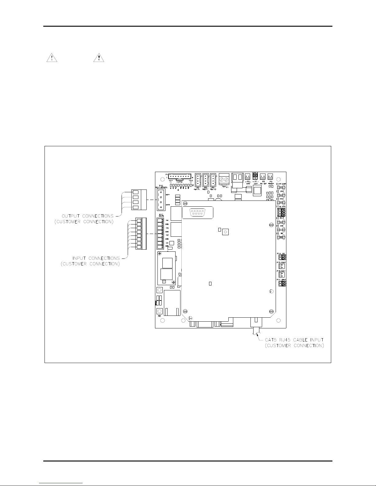
In addition to providing standard telephone operation, the VoIP
telephones feature real-time alarm reporting enabling system
supervisors to monitor the telephones’ activity and address
caller needs or maintenance issues immediately. Also, four
user-configurable inputs and two outputs have been provided
for peripheral control.
System Requirements and Limitations
GAI-Tronics VoIP Telephones require Power-over-Ethernet or
a local 48 V dc power source for operation. Two VoIP
telephones can be connected in a peer-to-peer configuration
without the need for a LAN, however, a 10/100 BaseT Ethernet
with SIP server is required for systems containing three or more
VoIP Telephones. Conferences are limited by the customer’s
LAN media capabilities and the services available at each end
point.
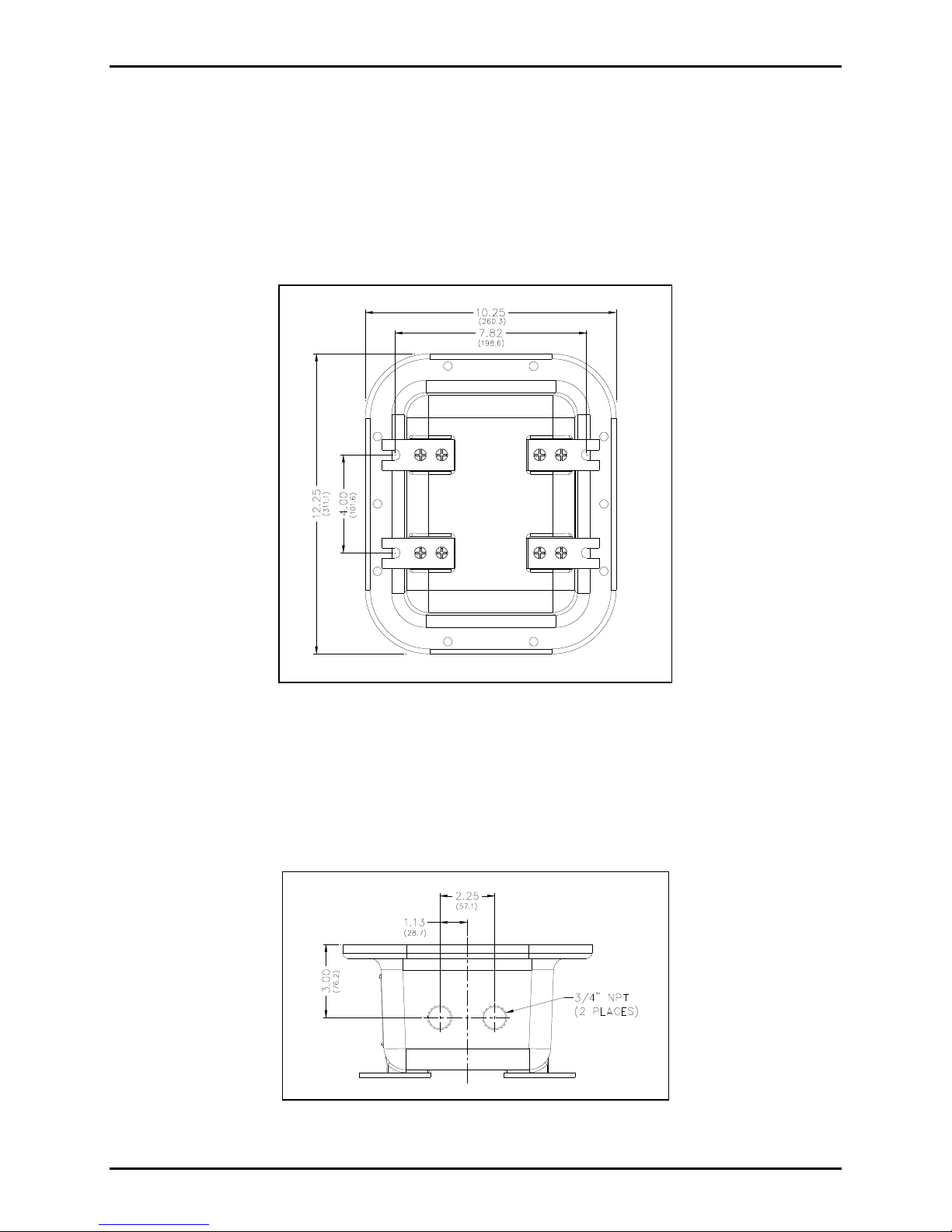
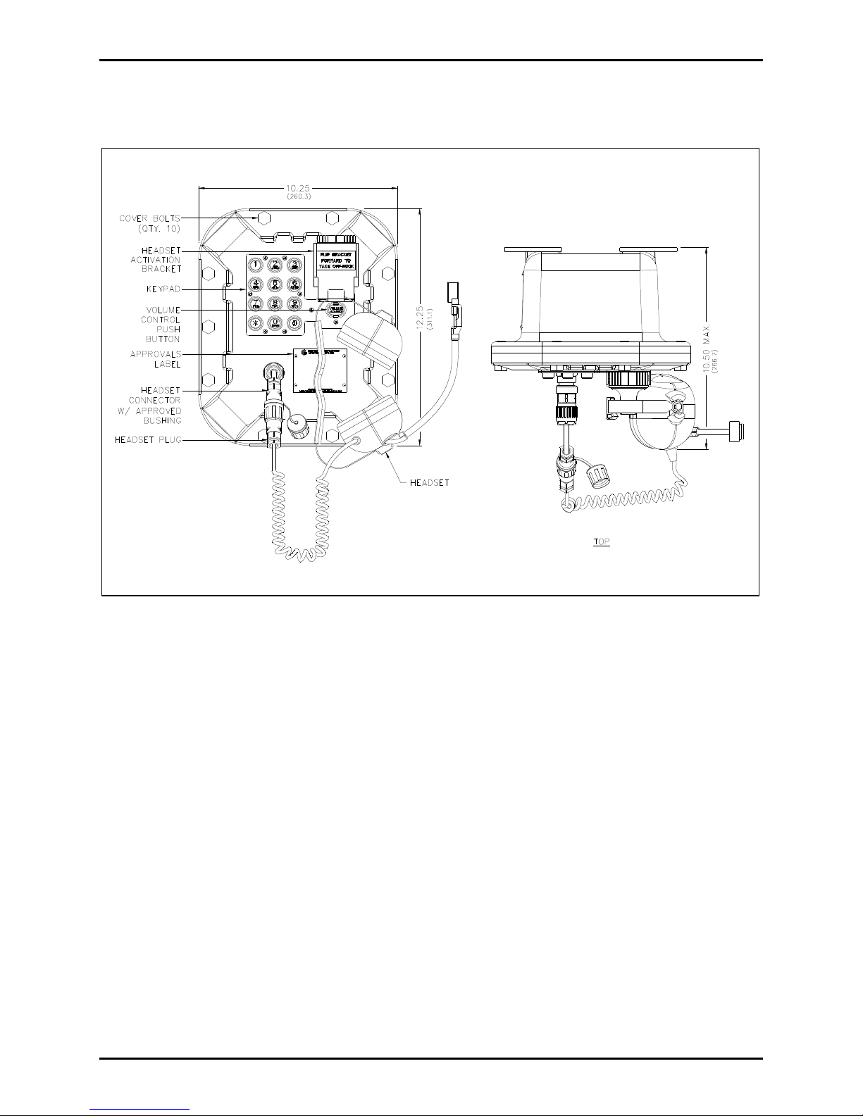
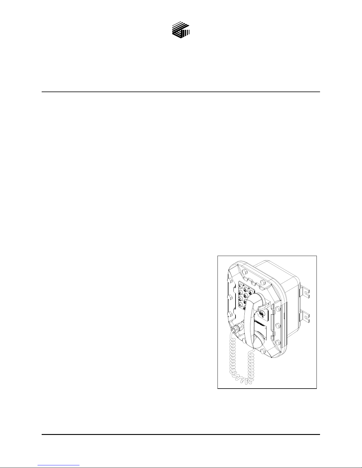
Figure 1. Model 352-701 Division 1
VoIP Telephone

Pub. 42004-456B
Model 352-701 and 352-703 Division 1 VoIP Telephones Page 2 of 20
e:\standard ioms - current release\42004 instr. manuals\42004-456b.doc
01/14
Tips for VoIP Subscribers
If you have or are thinking of subscribing to an interconnected VoIP service, you should:
Provide your accurate physical address to your interconnected VoIP service provider to ensure that
emergency services can quickly be dispatched to your location.
Be familiar with your VoIP service provider’s procedures for updating your address, and promptly
update address information in the event of a change.
If your power is out or your internet connection is down, be aware that your VoIP service may not
work. Consider installing a backup power supply, maintaining a traditional telephone line, or having
a wireless telephone as a backup.
If you have questions about VoIP in general, see http://www.fcc.gov/cgb/consumerfacts/voip.html.
Features and Functions
GAI-Tronics VoIP telephones include the following features:
SIP compatible (RFC3261)
Real-time alarm reporting via email or Syslog
Power-over-Ethernet compatible (Power Mode A, Class 0)
Configurable via web page, serial link or download
Four configurable auxiliary inputs and two configurable voltage-free contact outputs
Installation
Installation Guidelines
These enclosures must be installed by trained, qualified and competent personnel. Installation must
comply with state and national regulations, as well as safety practices for this type of equipment.
CAUTION Do not install this equipment in hazardous areas other than those indicated
on the approval listing in the “Specifications” section of this manual. Such installation may cause a
safety hazard and consequent injury or property damage.
The mounting location must be flat and provide proper clearance, rigidity and strength to support the
enclosure and all contained devices.

Pub. 42004-456B
Model 352-701 and 352-703 Division 1 VoIP Telephones Page 3 of 20
e:\standard ioms - current release\42004 instr. manuals\42004-456b.doc
01/14
WARNING Securely fasten the enclosure to the mounting location, using 3/8-inch diameter
steel mounting bolts and washers, or washer head bolts.
WARNING Do not disconnect equipment while energized.
Insure proper grounding to protective earthing.
WARNING The front cover is not hinged to the rear enclosure. When the cover bolts are
removed, the cover must be adequately supported.
ATTENTION Installation should be performed by qualified personnel and only in
accordance with the National Electrical Code or applicable local codes.
Inspect and clean the machined flange flame joint surfaces of both the cover and box. Surfaces must be
smooth, free of nicks, scratches, dirt or any foreign particle build-up that would prevent a proper seal.
Surfaces must seat fully against each other to provide a proper explosion-proof joint. Clean surfaces by
wiping with a clean lint-free cloth.
Apply a light coat of Killark “LUBG” lubricant to flange surfaces and close the cover. Install and tighten
all cover bolts to 30 ft-lbs. Make certain no cover bolts are omitted. Use only those bolts supplied with
the enclosure.
When installing any GAI-Tronics telephone equipment, please adhere to the following guidelines to
ensure the safety of all personnel:
Electrostatic Discharge (ESD) Protection: Your telephone has an earth ground terminal provision.
Ensure that it is connected to ground in accordance with all local safety regulations and the National
Electrical Code (NEC). Grounding must be ensured for safe and stable communications. Do not use
long and coiled ground wires. Trim ground wires to the required length. Please note proper
grounding does not eliminate the need for lightning protection for the telephone or the telephone
system.
NEVER install the telephone during a lightning storm.
Install a Cat5 data line lightning surge protector on any phone installed where the phone or phone
cable is at risk of being exposed to lightning strikes. The lightning arrestor must be installed as close
to the phone as possible in a non-hazardous environment. The lightning arrestor must not be installed
within the telephone enclosure.
USE CAUTION when installing or modifying Cat5 data lines.

Pub. 42004-456B
Model 352-701 and 352-703 Division 1 VoIP Telephones Page 4 of 20
e:\standard ioms - current release\42004 instr. manuals\42004-456b.doc
01/14
Mounting
NOTE:The mounting surface must be able to support the weight of the telephone, which is 28 lbs.
The enclosure must be securely fastened with 3/8-inch diameter steel mounting bolts located on all four
mounting feet. Stainless steel hardware is recommended in outdoor applications. Refer to Figure 2. The
suggested mounting height is 48 inches to the bottom of the enclosure.
NOTE:Refer to the Killark Installation, Operation, and Maintenance Data Sheet enclosed with the unit
for additional enclosure information.
Figure 2. Model 352 Series Division 1 VoIP Telephone Enclosure Mounting Details
Cable Entries
Refer to Figure 3 for the NPT conduit entries. Ensure any unused openings are sealed with proper fittings
per local standards. Use field wiring suitable for the ambient temperature. Any conduit NPT plugs
(blanking elements) must be explosion-proof with a Type 4X rating.
Figure 3. Model 352 Series Conduit Entries

Pub. 42004-456B
Model 352-701 and 352-703 Division 1 VoIP Telephones Page 5 of 20
e:\standard ioms - current release\42004 instr. manuals\42004-456b.doc
01/14
Hardware Description
External
Model 352-701 contains a handset with an approved cable gland, standard keypad, volume control button,
and applicable approval labeling. The handset rests on a cradle, which has a magnetic reed switch to
signal an off-hook condition. The enclosure is sealed with ten cover mounting bolts located around the
perimeter of the enclosure’s flange. See Figure 4.
Figure 4. Model 352-701 Division 1 VoIP Telephone Outline

Pub. 42004-456B
Model 352-701 and 352-703 Division 1 VoIP Telephones Page 6 of 20
e:\standard ioms - current release\42004 instr. manuals\42004-456b.doc
01/14
For the Model 352-703 Division 1 VoIP Telephone with the headset option, the cradle and handset are
replaced with a removable headset and headset activation bracket.
Figure 5. Model 352-703 Division 1 VoIP Telephone with Headset

Pub. 42004-456B
Model 352-701 and 352-703 Division 1 VoIP Telephones Page 7 of 20
e:\standard ioms - current release\42004 instr. manuals\42004-456b.doc
01/14
Internal
All standard components are mounted to the rear of the front cover. See Figure 6 for the parts layout.
Figure 6. Model 352-70xDivision 1 VoIP Telephone - Internal View

Pub. 42004-456B
Model 352-701 and 352-703 Division 1 VoIP Telephones Page 8 of 20
e:\standard ioms - current release\42004 instr. manuals\42004-456b.doc
01/14
Wiring
WARNING The front cover is not hinged to the rear enclosure. When the cover bolts are
removed, the cover must be adequately supported.
1. While supporting the front cover, remove the ten cover bolts on the enclosure flange. Pull the front
cover far enough away to expose the internal connections. Place the front cover aside.
2. Plug the incoming Cat5 data line to the network Cat5 cable receptacle on the underside of the VoIP
PCBA. See Figure 7.
Install any additional connections as indicated below. Refer to Figure 7, 8 and 9 for wiring details. Refer
to Table 3 on page 11 for the recommended conductor sizes.
Figure 7. VoIP Telephone PCB Assembly

Pub. 42004-456B
Model 352-701 and 352-703 Division 1 VoIP Telephones Page 9 of 20
e:\standard ioms - current release\42004 instr. manuals\42004-456b.doc
01/14
Figure 8. Input Cable Connections at P12 Figure 9. Output Cable Connections at P10
Figure 10.
Power
Power-Over-Ethernet (POE)
Connect power to the system as indicated in your POE equipment manual. (Power Mode A, Class 0)
Local Power
When POE is not available, this telephone can operate from a local 48 V dc power source. A removable
terminal block, P5, has been provided for connection of local power to the telephone. Connect the
positive conductor to the (+) terminal and the negative conductor to the (−) terminal of P5. Connection is
polarity sensitive.
Network Cable
Connect a Cat5 or Cat5e UTP cable with an RJ45 connector between the Local Area Network (LAN) and
the VoIP PCBA.
I/O
Inputs
Four auxiliary inputs have been provided for customer use. Terminations for these inputs are provided on
terminal block P12. Connect each input between the desired input (INPUT 1–4) and common (COM) on
terminal block P12. Refer to the “Inputs” section of Pub. 42004-481 for programming instructions of
these inputs.

Pub. 42004-456B
Model 352-701 and 352-703 Division 1 VoIP Telephones Page 10 of 20
e:\standard ioms - current release\42004 instr. manuals\42004-456b.doc
01/14
Table 1. Auxiliary Inputs – P12
Pin Label Function
1 IN4 Input 4
2 COM Common
3 IN3 Input 3
4 COM Common
5 IN2 Input 2
6 COM Common
7 IN1 Input 1
8 COM Common
Outputs
Two outputs have been provided for customer use. Terminations for these outputs are provided on
connector P10.
Each VoIP Telephone contains two voltage-free output contacts, but their ratings differ. Refer to the
“Specifications” section of this manual for the output ratings. Output 1 is a single-pole, single-throw
contact. Output 2 is a single-pole, double-throw contact.
The function of each output is configurable. Outputs can be configured for one of the following modes:
On, Off, Pulse, Mute, Ring, Call, Connect, Hook, In Use, Ring Cadence, Ring Out, Page, Registered, or
Emergency. In some modes, the duration of the activation or on/off times can also be set. Refer to the
“Logic Settings” section of GAI-Tronics Pub. 42004-481, “VoIP Telephone Configuration Guide” for
more details.
An external beacon or sounder can be activated with output 1 on the VoIP PCBA. The output must be
configured to “Ring” mode to activate the external device.
Table 2. Output Contacts – P10
Pin Label Description
1 C1 Common Output 1
2 NO1 Normally Open Output 1
3 C2 Common Output 2
4 NO2 Normally Open Output 2

Pub. 42004-456B
Model 352-701 and 352-703 Division 1 VoIP Telephones Page 11 of 20
e:\standard ioms - current release\42004 instr. manuals\42004-456b.doc
01/14
Table 3. Recommended Cabling
Cable Use Size
LAN Cat5 or Cat5e UTP cable with an RJ45 connector
Power Two-conductor, No. 22 AWG is typical
Inputs Two-conductor, No. 22 AWG is typical
Output contacts Two or three-conductor, No. 18 AWG is typical
Speaker Two or three-conductor, No. 18 AWG is typical
Status Indication
Power
The Power LED located on the VoIP PCBA illuminates when power is applied to the telephone.
Heartbeat
The Heartbeat LED located on the VoIP PCBA will flash once communication over the LAN is
established.
Figure 11. VoIP Carrier PCBA Component Locations

Pub. 42004-456B
Model 352-701 and 352-703 Division 1 VoIP Telephones Page 12 of 20
e:\standard ioms - current release\42004 instr. manuals\42004-456b.doc
01/14
Attach the Front Cover
After all adjustments have been completed, inspect and clean the machined flange joint surfaces of both
the cover and box. Surfaces must be smooth, free of nicks, scratches dirt or any foreign particle build-up
that would prevent a proper seal. Surfaces must seat fully against each other to provide a proper
explosion-proof joint. Clean surfaces by wiping with a clean lint-free cloth.
Apply a light coat of Killark “LUBG” lubricant to flange surfaces and close the cover. Install and tighten
all cover bolts to 30 ft-lbs. Make certain no cover bolts are omitted. Use only those bolts supplied with
the enclosure.
NOTE:Refer to the Killark Installation, Operation, and Maintenance Data Sheet enclosed with the unit
for additional information.
External Controls
Handset Receiver Volume Control
A push-button switch has been provided on the front cover of the telephone for adjustment of the handset
receiver volume. The receiver volume adjustment operates as follows:
The initial direction of the volume (increase or decrease) is determined by prior activity. The initial
direction will be opposite of the previous activity.
Changing the direction is accomplished by allowing a period of inactivity (greater than 1 second).
Example – Increasing Volume: Depress the volume switch. If the receiver volume begins to decrease,
wait at least 1 second and depress the volume switch again. The volume will begin to increase. When the
desired volume is achieved, do not depress the switch.
Maximum (Handset Receiver) Level Remote Control
The receiver volume level can be controlled remotely by changing the setting in the configuration file.
Refer to the “Handset Volume Setting in the Audio Setting” section in Pub. 42004-396 for programming
instructions.
NOTE:The handset receiver volume setting using PB1 should be set for the maximum volume (factory
default) prior to adjusting the volume remotely.

Pub. 42004-456B
Model 352-701 and 352-703 Division 1 VoIP Telephones Page 13 of 20
e:\standard ioms - current release\42004 instr. manuals\42004-456b.doc
01/14
Programming
Refer to Pub. 42004-396, VoIP Telephone Configuration Guide for detailed programming and
configuration instructions.
Quick Start Guide
For easier set up, configure the software prior to installing the telephone in a hazardous environment. The
general sequence for set up and use is as follows:
Stage of Process Comments
1. Initial network
configuration
Essential: The telephone must be set up for the network prior to
installation.
2. Assign a host name Recommended: The host name provides identification of the different
VoIP telephones on the network.
3. Change user name and
password
Recommended: This security measure helps to prevent unauthorized
changes to the telephone’s configuration.
4. Mounting Physically mount the telephone at the intended location.
5. Installation Provide telephone connections and cabling to the network at the
intended location.
6. Final configuration (can
also be done prior to
installation)
Set the autodial numbers, etc. Configuration changes can be performed
remotely, if desired.
7. Test Verify that calls can be made successfully.
8. Maintain Monitor alarms. Set up auto-updates.
The easiest way to get started is to make a network connection to the unit and log on via a web browser.
The unit is initially set with a static IP address:
IP address 192.168.1.2
A user name and password will be requested. The initial factory settings are:
User Name user
Password password
The telephone’s home page is as shown in Figure 12 below, and allows access to all the other
configuration pages. Use the Network page to change IP settings appropriate for the intended network.
ATTENTION Be sure to assign a unique host name (located on the UNIT settings page) for
each telephone on the network. The factory default host name in each unit is its serial number prefixed by
“GT”.
Full help is available from: www.gai-tronics.co.uk/voipsupport.htm

Pub. 42004-456B
Model 352-701 and 352-703 Division 1 VoIP Telephones Page 14 of 20
e:\standard ioms - current release\42004 instr. manuals\42004-456b.doc
01/14
A CD containing all help files and the configuration file tool is available from GAI-Tronics on request.
Figure 12.
Alternative Configuration Methods
There are three methods for configuring GAI-Tronics Handset VoIP telephones:
Web pages
Configuration file
Command Line interface (CLI)
Web pages (held within the telephone) can be accessed over the network using a browser such as Internet
Explorer™, to view and change settings within a single unit.
Configuration files are ASCII text files containing configuration options that can be read and edited by
VCONF (a dedicated software configuration tool), or directly by a knowledgeable user. The telephone
can automatically download a configuration file from the network, providing a controlled method of
configuring multiple telephones.
The telephone can also be configured using a command line interface, either via the local serial port or
remotely via a TELNET session over the network.

Pub. 42004-456B
Model 352-701 and 352-703 Division 1 VoIP Telephones Page 15 of 20
e:\standard ioms - current release\42004 instr. manuals\42004-456b.doc
01/14
Operation
Model 352-701 Handset Operation
1. Lift the handset to place a call.
2. The handset receiver volume control located on the front cover keypad, can be adjusted to the desired
level by pressing the volume control push button.
3. Dial the desired number.
4. After completion of the call, place the handset on-hook.
Figure 13.

Pub. 42004-456B
Model 352-701 and 352-703 Division 1 VoIP Telephones Page 16 of 20
e:\standard ioms - current release\42004 instr. manuals\42004-456b.doc
01/14
Model 352-703 Headset Operation
1. To connect the headset, plug it into the flexible plug on the front of the telephone by removing the
sealing cap from the receptacle, aligning the connector pins, and screwing the two ends together. See
Figure 14.
Figure 14.
2. To place a call, remove the headset from the headset activation bracket and flip the headset bracket
forward to its preset position.
3. The handset receiver volume control, which is located on the front cover keypad, can be adjusted to
the desired level by pressing the volume control push button.
NOTE:Pressing the volume control push button increases the volume in 3-dB increments. The
volume starts at 0 db and increases to a maximum volume of 18 dB. Pressing the volume control
push button a seventh time will return the volume to 0 dB.
4. Dial the desired number.

Pub. 42004-456B
Model 352-701 and 352-703 Division 1 VoIP Telephones Page 17 of 20
e:\standard ioms - current release\42004 instr. manuals\42004-456b.doc
01/14
5. Flip the headset activation bracket to its vertical preset position to hang up. If applicable, place the
headset on the bracket after the completion of the call. Otherwise, disconnect the flexible receptacle
and plug by unscrewing the two ends, and pulling them apart. When disconnected, reattach the
sealing cap to the end of the receptacle.
Figure 15.
Maintenance
Service
If your telephone requires depot service, contact your Regional Service Center for a return authorization
number (RA#). Equipment should be shipped prepaid to GAI-Tronics with a return authorization number
and a purchase order number. If the equipment is under warranty, repairs will be made without charge.
Please include a written explanation of all defects to assist our technicians in their troubleshooting efforts.
Call 800-492-1212 inside the USA or 610-777-1374 outside the USA for help identifying the Regional
Service Center closest to you.

Pub. 42004-456B
Model 352-701 and 352-703 Division 1 VoIP Telephones Page 18 of 20
e:\standard ioms - current release\42004 instr. manuals\42004-456b.doc
01/14
Troubleshooting
Table 4. Troubleshooting Chart
Problem Possible Solution
Low volume in handset
or headset
Increase the volume setting using the Volume Adjust button on the front
panel.
NOTE:There is no external speaker adjustment.
High volume in handset
or headset
Decrease the volume setting using the Volume Adjust button on the front
panel.
NOTE:There is no external speaker adjustment.
Front panel push buttons
are not operational
Verify the push buttons are properly configured.
Inputs not operational Check the input connections.
Verify the inputs are properly configured.
Outputs not operational Check the output connections.
Verify the outputs are properly configured.
Cannot make or receive
calls
Check the connection of the LAN cable.
Verify that power is applied to the unit.
Verify the LAN parameters have been configured properly.
Verify the telephone has been set up on the network.
No power indication Check the power connections.
If using POE, check the operation of the POE equipment.

Pub. 42004-456B
Model 352-701 and 352-703 Division 1 VoIP Telephones Page 19 of 20
e:\standard ioms - current release\42004 instr. manuals\42004-456b.doc
01/14
Specifications
Power ............................... Power-over-Ethernet, 802.3af compliant (via RJ45) Power Mode A, Class 0, or
External power supply: 48 V dc, 200 mA
A separate, isolated supply must be provided for each telephone.
Network ........................................................................... 10/100 BaseT Ethernet RJ45, Cat5 or Cat5e UTP
Static IP provisioning or DHCP STUN client (NAT traversal)
Call control signaling.................................................................... SIP (RFC3261 compliant) Loose routing
Inputs
Keypad ........................................................................................................................................ 3 4 matrix
Configurable inputs................................................................................................................................. Four
Outputs
Output 1 ......................................................................................... 8 A @ 250 V ac/30 V dc (resistive load)
Output 2 ......................................................................................... 5 A @ 250 V ac/30 V dc (resistive load)
Controls
External.............................................................................................................. Push-button volume control
Internal ............................................................................................... Mic bias, reset switch, handset enable
Indicators
Internal ..................................................................................................... Power, Heartbeat, & EACT LEDs
Codecs and audio ..................................................................................................................... G.711 A-Law
G.711 µ-Law
G.722
G.729
G.723.1 MP-MLQ
G.723.1 ACELP
Codec preference sequence
DTMF in-band / out-of-band (RFC2833)
Configurable comfort tones (to emulate national tones)
Configuration .............................................................................................................. Embedded web server
Embedded Telnet server
Configuration file download
Configuration file building tool (Vconf.exe)
Direct serial connection
(Nine-way D-type female connector)
Command line interface
SNTP with time zone and daylight saving
Automatic updating via TFTP
Password protection
Monitoring and reporting........................... Real-time over TCP/IP proprietary Syslog application or email
Embedded SMTP client
Automatic fault reporting
Compliance to Standards .............................................................................................. FCC CFR 47 Part 15

Pub. 42004-456B
Model 352-701 and 352-703 Division 1 VoIP Telephones Page 20 of 20
e:\standard ioms - current release\42004 instr. manuals\42004-456b.doc
01/14
Environmental
Operating temperature .......................................................................... −4º F to +140º F (−20º C to +60º C)
Humidity ...................................................................................................................... 95% non-condensing
Mechanical
Enclosure .............................................................................. Cast aluminum with aluminized lacquer paint
Handset Cord .......................................................“G” style handset/PVC 6-foot extended length (standard)
Connection ............................................................................................................................ RJ45 receptacle
Dimensions, outside................................ 10.25 W 12.25 H 9.50 D inches (260.3 311.1 241.3 mm)
Mounting.................................................. Wall or column, four 3/8-inch (10 mm) mounting feet with slots
Shipping weight ................................................................................................................ 30.0 lbs. (13.6 kg)
Net weight......................................................................................................................... 28.0 lbs. (12.7 kg)
Approvals
NRTL listed ...................................................... Hazardous locations Class I, Division 1, Groups B, C, & D
(USA and Canada) Class II, Division 1, Groups F & G
Class III, Division 1
Type 4X
T6 – Gas
T4A – Dust
User Instructions (USA)
This equipment has been tested and found to comply with the limits for a Class A digital device, pursuant to part 15 of the FCC
Rules. These limits are designed to provide reasonable protection against harmful interference when the equipment is operated in
a commercial environment. This equipment generates, uses, and can radiate radio frequency energy and, if not installed and used
in accordance with the instruction manual, may cause harmful interference to radio communications. Operation of this
equipment in a residential area is likely to cause harmful interference in which case the user will be required to correct the
interference at his own expense.
This manual suits for next models
1
Table of contents
Other GAI-Tronics IP Phone manuals

GAI-Tronics
GAI-Tronics Red Alert 393-800A User manual

GAI-Tronics
GAI-Tronics RED ALERT 397-700CB User manual

GAI-Tronics
GAI-Tronics 1114 User manual

GAI-Tronics
GAI-Tronics RED ALERT 397-710CB User manual

GAI-Tronics
GAI-Tronics Clean Phone 295-702W User manual

GAI-Tronics
GAI-Tronics Titan User manual

GAI-Tronics
GAI-Tronics L3149B User manual

GAI-Tronics
GAI-Tronics ACC2500 Operating manual