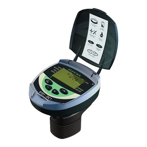
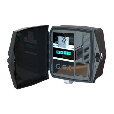
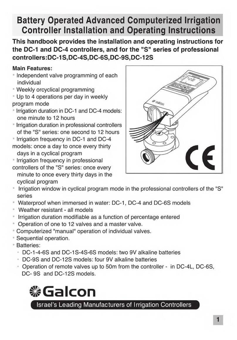
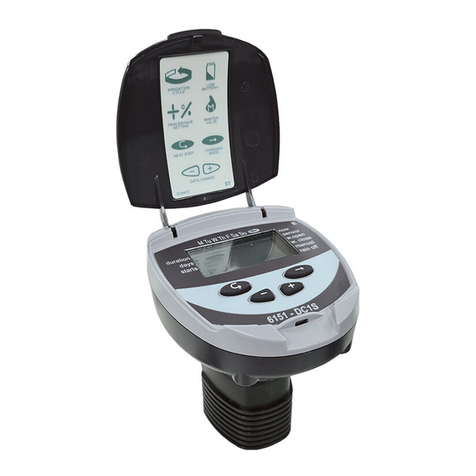
Galcon Gal Pro DC User manual

GalPro
AC/DC
Operating Manual


Gal Pro Instruction 1.0
Gal Pro
Thank you for choosing Galcon’s Gal Pro controller.
Galcon Company has invested its comprehensive knowledge, accumulated throughout the years, to
develop a new irrigation controller that answers the high demands of agriculture.
The controller excels in its new hardware and software. A great deal of emphasis was placed on
user friendliness. The Gal Pro allows you to enjoy high performance, data collection and reliability for
many years. All this, at a very low, unprecedented price.
Please read the operating manual before undertaking any action on the controller.
We wish you enjoyable and efficient use throughout the years.
The Galcon team

Gal Pro Instruction 1.0
1. Preface ................................................................................................................................. 5
2. Controller Description ........................................................................................................... 6
3. Installation ............................................................................................................................ 8
a. Physical connection .................................................................................................. 8
b. Output connection ..................................................................................................... 9
c. Input Connection ..................................................................................................... 11
d. Power Supply .......................................................................................................... 11
4. First Operation .................................................................................................................... 14
5. Controller Definition ............................................................................................................ 16
a. Service Menu .......................................................................................................... 16
b. System Setup Menu ................................................................................................ 17
c. Water Meter Menu .................................................................................................. 19
d. Fertilizer System Menu ........................................................................................... 20
e. Filter Flush System Menu ....................................................................................... 21
f. Alarm Menu ............................................................................................................. 22
g. Log Books Menu ..................................................................................................... 22
6. Programming ...................................................................................................................... 23
a. Valves - Water and Fertilizer Programs .................................................................. 24
b. Sequence Setup ..................................................................................................... 26
c. Sequence Timings .................................................................................................. 27
7. Information and Programming ............................................................................................ 28
a. System Status ......................................................................................................... 28
b. Valve Status ............................................................................................................ 29
c. Valve Information .................................................................................................... 30
d. Sequence Status ..................................................................................................... 31
e. Sequence Information ............................................................................................ 32
8. Manual Overriding .............................................................................................................. 36
9. Alarm Menu ........................................................................................................................ 37
10. Data Loggers ...................................................................................................................... 38
11. Advance operation guide .................................................................................................... 39
a. Flow Control Mechanism ........................................................................................ 39
b. Condition Input Operation ....................................................................................... 40
12. Maintenance ....................................................................................................................... 42
a. Output Checkup ...................................................................................................... 42
13. Technical Specification ....................................................................................................... 43
Index
Gal Pro Instruction 1.0
The Gal Pro is a small economical controller designed for the irrigation and fertilization of plantations,
orchards and small to medium sized open fields.
The Gal Pro is produced in two sizes:
Gal Pro 4:
Designed to operate 4 Irrigation valves, Master valve, Fertilizer pump, 2 filters, and an Alarm output.
Gal Pro 8:
Designed to operate 8 Irrigation valves, Master valve, Fertilizer pump, 2 filters and an Alarm output.
Gal Pro is manufactured in two configurations,
Gal Pro DC:
The controller operates 2 or 3 wires 12VDC Latching solenoids.
The controller is operated by 4 * 1.5 volt batteries (installed inside the controller casing) or an external
power supply of 12 VDC - disposable dry battery or rechargeable battery of 5-7 Amp.* Hours. Using
the rechargeable battery requires the use of an adequate power supply with an output of 13.8 volts
or a solar panel of 5 Watts.
Gal Pro AC:
Operated by standard socket of 220V or 110V. If necessary protection cards can be added for
controller's inputs and outputs.
The controller operates solenoids of 24VAC type.
In both of the controller's configurations the controller's outputs and inputs are predefined and fixed.
The definitions and programming data are maintained even when the controller is disconnected from
power. However some types of data are lost. The data that is lost when disconnected are: time, date,
accumulations of water and fertilizers and data loggers.
In Gal Pro AC a 9V battery can be connected in order to preserve all the data during a power failure.
1. Preface

Gal Pro Instruction 1.0
2. Controller Description
1. Display - 5 alphanumeric display rows.
The first row shows the current position of the menu.
The next 4 rows show information and enable programming.
The display is normally off. Pressing any key or turning the "Menu Selector" turns the display
on. When the keys are untouched for more than two minutes the display turns off.
2. Keyboard (7 keys)
The keyboard provides navigation, information and programming.
3. Menu Selector (16 positions)
The selector enables direct access to all of the controller options. It is possible to turn the
selector in both directions.
2. Keyboard
3. Menu Selector
1. Display

Gal Pro Instruction 1.0
4. Battery Compartment - 4 * D type 1.5 Volt batteries for Gal Pro DC
5. Power Supply Connectors - Connect the internal batteries or external power supply. Please
see the explicit instructions in the Controller Installation chapter.
6. Input Connectors - Connect the water meters, fertilizer meters and conditioned inputs such
as pressure stat, differential pressure stat etc.
7. Output Connectors - Connect the system solenoids and alarm outputs.
8. Reset Button on CPU - Pressing this button resets the following parameters: time and date,
logs and accumulations. Controller definitions and irrigation programs are not affected by the
reset button. Only use this button if experiencing severe disruption of the controller activity.
2. Controller Description
4. Battery Compartment 5. Power Supply Connectors
6. Input Connectors 7. Output Connectors 8. Reset Button on CPU

Gal Pro Instruction 1.0
Physical Connections
The controller is designed to withstand sunny and rainy weather conditions. However it is preferable
to provide additional protection from the climate by installing it in a sheltered position. Appropriate
installation of the controller will ensure its dependable running throughout the years.
The controller can be installed in two ways:
• Mounted on a wall or any vertical board.
• On a 1¼" - 1½" diameter metal post via the provided bands.
3. Controller Installation
Wall Mounting Diagram
Metal Post Mounting Diagram

Gal Pro Instruction 1.0
Output Connections
The Gal Pro 4 has 9 outputs:
4 Irrigation Valves
Master Valve
Fertilizer Pump
2 Filters
Alarm
The Gal Pro 8 has 13 outputs:
8 Irrigation Valves
The rest pf the outputs are identical to the Gal Pro 4
The solenoids are installed on a bar below the controller.
Output Connection Diagram:
1. Remove all of the detachable connectors.
2. Insert the solenoid wires via the antigrons on the bottom of the casing and connect them to
the detachable connectors. Please make sure that the wires are connected correctly according
to their coloring.
Three Wire Solenoid Connection for Gal Pro DC.
Please Note!!! The wires are connected according to the following order:
3. Controller Installation
RedBlackWhite

10
Gal Pro Instruction 1.0
Two wire solenoids for Gal Pro DC (black and red wires only) are connected in the same way (the
white wire connector is left unconnected). In this way the solenoid is "normally open" i.e. when the
output is idle the solenoid sends water. When inverting the command is required, simply switch
between the red and black wires.
Connection of solenoids for Gal Pro AC
The red wire has to be connected to the output and the second wire has to be connected to the
COM.
*It is highly recommended to mark with an indelible pen all of the output functions.
Connect all of the detachable connectors.
Alarm Output Connection
The alarm output is designed to send out an alarm. The alarm output can be connected to devices
such as: a siren, flashing lights, a cellular dialer that sends text messages etc. The alarm device is
operated via an external power supply for Gal Pro DC Controller with a relay switch connected to
the controller.
Alarm Connection Diagram:
3. Controller Installation
12VDC
OUT PUT
COMMON

11
Gal Pro Instruction 1.0
Input Connections
The controller has the following inputs:
4 Water Meters
Fertilizer Meter
3 Condition inputs - these inputs are connected to devices and enable to condition the controller
programming on the input contact by condition types such as: start, stop, pause or operate. The
condition devices include:
Pressure Stat - a device that enables pausing the system in the case of low pressure.
Differential Pressure Stat - a device that enables flushing filters according to the pressure differential
over the filters.
Thermostat - a device that enables irrigation during extreme temperatures.
Electric Tensiometer - a device that enables starting irrigation according to the soil humidity.
Please Note: The first row includes (from
left to right): 4 water meters, fertilizer meter
and 3 commons.
The second row includes: The 3 condition
inputs and 5 commons.
1. Remove all of the detachable input connectors.
2. Insert the solenoid wires via the antigrons on the bottom of the casing and connect them to
the detachable connectors. (Every input has 2 wires - "input" and "common")
It is highly recommended to mark with an indelible pen all of the output functions.
3. Connect all of the detachable connectors.
Power Supply to Gal Pro DC Controller
As stated in the preface the controller can be powered by 4 * D type 1.5 volt batteries installed in the
controller casing or by a 12 VDC external power supply.
Please Note: During first time operation you will be requested to define the power supply voltage.
When the controller is used for intensive operation it is recommended to use an external power
supply.
Intensive operation includes the following situations:
The controller operates many valves and fertilization.
The controller irrigates several times a day.
Fertilization is proportional i.e. the fertilizer pump starts and stops frequently during the irrigation.
3. Controller Installation

12
Gal Pro Instruction 1.0
When using an external power supply please use a rechargeable battery of at least 5 amp.* hours
connected to a suitable charger. When the controller is located in the vicinity of the power network,
you may connect the charger to the network. If not, use a solar panel in order to charge the battery.
Please Note: When using a solar panel it is recommended to use a charge controller to protect the
battery from overcharging.
Internal Battery Power Supply
1. Remove the battery compartment cover by unscrewing the 2 Phillips screws.
2. Insert the 4 * alkaline D type 1.5 Volt batteries. Please pay attention to the position of the
batteries.
3. Close the battery compartment.
4. Connect the power supply connector to the "BAT IN" connector on the terminal board.
External Power Supply
Install the rechargeable 12 VDC (at least 5 amp. * hours) battery next to the controller in suitable
3. Controller Installation

1
Gal Pro Instruction 1.0
casing. Connect the battery to the "PWR" connector on the terminal board. Pay attention to the
polarity.
The "BAT OUT" connector on the terminal board is designed to
supply power to an "Amiad" fertilizer pump pulse transmitter
or other uses.
Power supply to Gal Pro AC controller
From Gal Pro AC controller exits a standard electriccable of 220V
or 110V (as ordered).
3. Controller Installation
Solar Panel
Battery
Charge
Controller

1
Gal Pro Instruction 1.0
When connected to the power supply for the first time the following screen appears:
The controller initializes (closes) the outputs. This process lasts several seconds, at the end of the
initialization the following message appears:
Initiate Output: 00
Press Enter to continue
Keyboard
The keyboard includes the following keys:
The arrow keys are used to move between the rows of the controller screen.
The "Next" and "Prev" keys are used to move between elements in multi-element screens such
as: valves, sequences, water meters and paging the log book.
The "+" and "-" keys are used to change the numeric value in programming and the selection of
different options in the definition of the controller. Continual depression of these keys accelerates
the rate of change of the numbers.
Simultaneous depression of "Enter" and "+" or "-" changes the numbers by tens.
The "Enter" key is used to enter some of the data into the controller:
1. Confirm changes of programming parameters.
2. To confirm some system actions when the "Press Enter to Continue" message ppears.
3. To accelerate the number rate change.
4. When restoring factory defaults. See explanation in the "Controller Definition" chapter.
4. First Time Operation

1
Gal Pro Instruction 1.0
Menu Selectors
The controller menus appear around the 16 state "Menu Selector". They are divided into the
following 4 groups:
Group A: Irrigation system data - black letters on grey background.
Sequence Status - Current information about sequence timing and valve status in the
sequence. Most of the parameters in this menu are editable.
System Status - General controller status information.
Valve Status - Current irrigation valve status. Some of the data is editable.
Valve Info - Valve timing and accumulation information.
Sequence Info - Additional data for sequence follow up. Not editable.
Group B: Irrigation Programming - blue letters on black background.
Valves Water and Fertilizer - Valve water and fertilizer programming.
Sequence Timing - Timing program for the sequences.
Group C: System definition and constants - blue letters on grey background.
Sequence Setup - Sequence constant data.
System Setup - System operation, flow control, condition input constants.
Services - Clock update, input/output status checkup, battery power checkup, direct
output manual operation and controller reset.
Filter Flushing - Filter flush definition and checkup.
Fertilization - Fertilizer pump definition and data.
Water Counters - Water counter definition and accumulation data.
Group D: Operation and reports - grey letters on black background.
Manual Overriding - enables manual operation.
Alarms - alarm information and cancel.
Diaries - Controller operation history. Up to 128 events are listed.
4. First Time Operation

1
Gal Pro Instruction 1.0
During first time operation and before programming irrigations, some initial parameters must be entered.
Service Menu
a. Date and Time Update
1. Turn the selector to the "Service Menu", press the "Enter" key. On the right side of the screen
an arrow that marks the first row appears. In addition a cursor appears as an underscore below the
"hours" of the clock. This cursor signifies that the data above it can be changed.
2. Edit the time via the "+" and "-" keys.
3. Press the "Next" key to move the cursor to the "minutes" and adjust accordingly.
4. If necessary move the cursor to the "seconds" and adjust accordingly.
5 .Move down one row, the cursor appears under the "day" of the date. Adjust it accordingly.
6. Move the cursor to the right and adjust the "month" and the "year". The day of the week which
appears on the right of the date will update automatically.
b. Voltage and Screen Contrast Definition
1. For Gal Pro DC Move down and skip the following rows: Input Status, Output Status, System
Version and Voltage Display. The following row is "battery type". Define the voltage used, 6 Volts if
using internal batteries and 12 Volts if using an external power supply.
2. Move down one more row and select the screen contrast level (5 is the default)
c. Solenoid Pulse Duration Definition For Gal Pro DC
In order to enable the use of different types of solenoids it is possible to define the pulse duration. The
default pulse duration is 80 ms. It is recommended to consult Galcon technicians before changing
this parameter.
1. Move down until you reach "out.command m.s 80". Via the "+" and "-" select the required pulse
duration.
d. Restoring Factory Defaults
The following operation enables you to initiate the controller. All data apart from the time and date
will be erased. It is recommended to perform initialization before first time operation.
1. Move down until you reach "load Dflt Setup" and via the "+" key select the "Yes" option. The
message "Enter Password Keys" appears. Press the "Prev", "Enter" and "Next" keys simultaneously.
The system closes all solenoids and loads the default data. At the end of this process the "Load
Setup Complete" message appears.
5. Controller Definition
Services
System Setup
Sequence Setup
Filter Flush
Fertilization
Sequence Timing
Valve • Water & Fert.
Water Counter
Diaries
Alarms
Valve Info
Sequence Info
Manual Overriding
Sequence Status Valve Status
System Status

1
Gal Pro Instruction 1.0
e. Output Initialization
The controller performs the initialization process automatically when connected to the power. Usually
there is no need to perform this process unless you want to technically check solenoids due to
replacement. Details about this process are further explained in the "Maintenance" chapter.
f. Irrigation Head Definition
System Setup Menu
Turn the selector to the system setup menu and enter the required
definition according to the following table: (the values shown in the
"Example" column are for illustration purposes only - please enter
(when applicable) your required values)
Subject Example Explanation
System
Active
At this stage leave the head Not Active.
Options:
System Not Active - Stops all system activity and erases the
accumulation data. The programming data and constants are
not affected.
System Active - System is active - the normal status.
Fixed System Pause - Stops all system activity.
Fixed Main Open - The system is working automatically
(normally), the main valve is always open. It will only close in
the case of a fault.
Queue Operation Yes Yes - Sequences work one at a time (not simultaneously).
No - Sequences work simultaneously under the following
conditions:
a. Irrigation without fertilizers.
b. Fertilization when the units are liter/m3 with the same
amount and without "water before/after".
c. One of the valves is not on the fertilizer route.
Opn.Main Order Aft. Aft. - The main valve opens after the irrigation valve.
Sim. - The main valve opens simultaneously with the
irrigation valve.
Bef. - The main valve opens before the irrigation valve.
Open Delay Sec. 10 The time delay between the main and irrigation valve
according to the previous definition.
Cls.Main Order Bef. See "Open Main Order".
Close Delay Sec. 20 The time delay between the main and irrigation valve
according to the previous definition.
5. Controller Definition
Services
System Setup
Sequence Setup
Filter Flush
Fertilization
Sequence Timing
Valve • Water & Fert.
Water Counter
Diaries
Alarms
Valve Info
Sequence Info
Manual Overriding
Sequence Status Valve Status
System Status

1
Gal Pro Instruction 1.0
Subject Example Explanation
Overlap Time Sc. 10 The closing valve closes 10 seconds after the next valve in
order to prevent water shock.
Pause-Cond.Input 1 If using "condition input" in order to "pause" the whole
system, enter the number here. See detailed explanation in
"Advanced Operation" (p.40).
Fill-Dly m3 2.0 Amount of water passing through the water meter from the
start of irrigation until activating flow alarms.
Fill Delay Mnt. 5 The time that passes from start of irrigation until activating
flow alarms.
If both fill delays (time and amount) are defined the first to
occur will activate flow alarms.
Flow Dev. Unit M3/H The unit for flow control (M3/H or %).
Flow Delay Unit. M3 The flow delay unit for the definition in "Valve - Water&Fert."
menu.
Fixd.Wtr Mult. 100% Enables changing the amounts of all the valves at once. 0
- 200 %. When programmed "Water Mult." appears in the
"System Status" menu.
Fixd.Cancl Fert No Cancel fertilizing even though there is a fertilizer program.
Cnd.1 OnDly-Sc 10 Delay in seconds to start according to condition input.
Cnd.1 OffDly-S. 10 Delay in seconds to stop according to condition input.
Cnd.2 OnDly-Sc. 10 See Condition 1.
Cnd.2 OffDly-S. 10 See Condition 1.
Cnd.3 OnDly-Sc. 10 See Condition 1.
Cnd.3 OffDly-S. 10 See Condition 1.
5. Controller Definition

1
Gal Pro Instruction 1.0
5. Controller Definition
Water Counter Menu
Turn the selector to the "Water Counter" menu.
The upper row shows Water Counter No. 1
Move down until you reach Wtr.Counter Setup.
Enter the parameters as follows:
Subject Example Explanation
Puls.Size Ltr 100 Define the pulse size according to the water counter
specification.
Pulse Dly-Sec. 300 The "time out" definition during which the controller waits for
a water pulse before activating "no water pulse" alarm.
Fault React Fault The following options only apply when the irrigation unit is
by Time. If the irrigation unit is according to Volume it will
always create a fault.
Fault - Reaching the "time out" from the previous item issues
a fault message, stops the current valve and starts the next
valve in the sequence.
Two consecutive faults of this type causes the water meter to
fault and all of the valves using this water meter will not work.
Ignore - The controller continues irrigating.
Alarm - During this fault the controller issues an alarm but
does not stop irrigation.
Leak.Set-m3 5 The amount of water in M3 that the system allows when all
of the valves are closed before issuing the "leak" alarm. It
resets at the start of each irrigation.
Leak.Reaction Fault Fault - The controller will not allow irrigation and issues an
alarm.
Ignore - The programs using the water meter will irrigate
normally.
Alarm - During this fault the controller issues an alarm but
allows irrigation.
If the system has more than one water meter, access the next screen via the "Next" key.
Services
System Setup
Sequence Setup
Filter Flush
Fertilization
Sequence Timing
Valve • Water & Fert.
Water Counter
Diaries
Alarms
Valve Info
Sequence Info
Manual Overriding
Sequence Status Valve Status
System Status

20
Gal Pro Instruction 1.0
5. Controller Definition
Fertilization Menu
Turn the selector to the "Fertilzation" menu.
The first row shows Pump Status N.Active
Move down until you reach: Fert. Pump Setup
Enter the parameters as follows:
Subject Example Explanation
Pump Type By Pulse When the system has a fert. counter, define: By Pulse
if not define: Venturi
Puls.Size Mil 100 Only define if the system has a fert. counter.
Pump.Flow L/H 200 L/H This parameter must be defined when the pump is defined as
Venturi. If it is not defined a
"Fert. Pump Error" message appears.
Pulse Time Sec. 10 This parameter is necessary when operating a Venturi type
fertilizer pump with proportional fertilization.
Continuous Yes During proportional fertilization:
Yes - The fertilizer pump fertilizers all of the required amount
between 2 pulses of water continuously.
No - The fertilizer pumps work alternately between the 2
pulses of water according to the previous parameter.
Pipe Delay-Sec. 10 Defines the amount of time before starting the fertilizer pump
in order to stabilize the water pressure.
Water Delay-Puls. 3 The number of water pulses that pass through the water
meter before the fertilizing process starts.
No Pulse Sec. 180 The time out of the fertilizer pulses. If after that time a pulse
is not received the system alarms. This could be due to lack
of water or a faulty fertilizer meter.
Leakage Pulses 10 The maximum number of pulses that the system allows
before issuing an alarm. This parameter helps to prevent
false alarms.
Auto Reset Flts No In the case of automatic alarm canceling, whether the
fertilizer pump participates in the alarm canceling. It is
recommended to select No.
Services
System Setup
Sequence Setup
Filter Flush
Fertilization
Sequence Timing
Valve • Water & Fert.
Water Counter
Diaries
Alarms
Valve Info
Sequence Info
Manual Overriding
Sequence Status Valve Status
System Status
This manual suits for next models
3
Table of contents
Other Galcon Controllers manuals

Galcon
Galcon 11000BT User manual

Galcon
Galcon DC-11SF User manual

Galcon
Galcon AC 4 User manual

Galcon
Galcon Galileo Manual

Galcon
Galcon 7001D User manual

Galcon
Galcon Dc-1 User manual

Galcon
Galcon S Series User manual

Galcon
Galcon 7101BT User manual

Galcon
Galcon AMC-6DC User manual

Galcon
Galcon Galileo User manual
Popular Controllers manuals by other brands

Micro Mod
Micro Mod 53SL5100B instruction manual

Lutz-Jesco
Lutz-Jesco TOPAX L quick guide

Allen-Bradley
Allen-Bradley powerflex 700 user manual

Xantrex
Xantrex Trace C35 Installation and operation guide

brummerhoop
brummerhoop Lago 0321 Operating and installation instructions

TECSYSTEM
TECSYSTEM NT579 instruction manual