manuals.online logo
Brands
  1. Home
  2. •
  3. Brands
  4. •
  5. Garland
  6. •
  7. Network Hardware
  8. •
  9. Garland P10GXXA-X User manual

Garland P10GXXA-X User manual

This manual suits for next models

1

Other Garland Network Hardware manuals
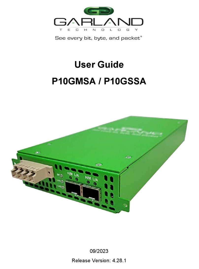
Garland P10GMSA User manual

Garland

Garland P10GMSA User manual

Garland INT40G2-44 User manual

Garland

Garland INT40G2-44 User manual

Garland INT10G12 V2 Series User manual
Garland

Garland INT10G12 V2 Series User manual

Garland P10GMSA-5 User manual

Garland

Garland P10GMSA-5 User manual

Garland PacketMAX AA1G52ACV2 User manual

Garland

Garland PacketMAX AA1G52ACV2 User manual

Garland P1GCSSP User manual

Garland

Garland P1GCSSP User manual

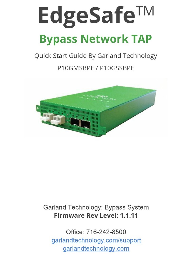
Garland P10GMSBPE User manual

Garland

Garland P10GMSBPE User manual

Garland P1GCCAS User manual

Garland

Garland P1GCCAS User manual

Garland P10GSFPA User manual

Garland

Garland P10GSFPA User manual

Garland P1GCCB User manual

Garland

Garland P1GCCB User manual

Garland P1G-BP Series User manual

Garland

Garland P1G-BP Series User manual

Garland INT40G2SR44 User manual

Garland

Garland INT40G2SR44 User manual

Garland AggregatorTAP INT1G10CSA User manual

Garland

Garland AggregatorTAP INT1G10CSA User manual

Garland INT10G8SR56-SP User manual

Garland

Garland INT10G8SR56-SP User manual

Garland P10GMSBPE User manual

Garland

Garland P10GMSBPE User manual

Garland FieldTAP P1GCUA mini User manual

Garland

Garland FieldTAP P1GCUA mini User manual

Garland P10GSFPBPFE User manual

Garland

Garland P10GSFPBPFE User manual

Garland P1GCCAS User manual

Garland

Garland P1GCCAS User manual

Garland EdgeLens INT10G8LR56 User manual
Garland

Garland EdgeLens INT10G8LR56 User manual

Garland M1GCCB User manual

Garland

Garland M1GCCB User manual

Garland INT10G10SP1 User manual

Garland

Garland INT10G10SP1 User manual

Garland PacketMAX GAA10G10AC User manual

Garland

Garland PacketMAX GAA10G10AC User manual

Garland EdgeLens Focus User manual

Garland

Garland EdgeLens Focus User manual

Garland EdgeSafe M40G1AC User manual

Garland

Garland EdgeSafe M40G1AC User manual

Popular Network Hardware manuals by other brands

socomec SNMP Card II quick start guide

socomec

socomec SNMP Card II quick start guide

NVR SYSTEMS 4-CH user manual

NVR SYSTEMS

NVR SYSTEMS 4-CH user manual

Draytek VigorSwitch G1240 quick start guide

Draytek

Draytek VigorSwitch G1240 quick start guide

Westermo TD-34 LV installation manual

Westermo

Westermo TD-34 LV installation manual

LaCie Network Space MAX Quick install guide

LaCie

LaCie Network Space MAX Quick install guide

ZoneVu ZSI-450-IP Installation guide & user manual

ZoneVu

ZoneVu ZSI-450-IP Installation guide & user manual

QNAP Turbo NAS Application notes

QNAP

QNAP Turbo NAS Application notes

OpenEye MV Series quick start guide

OpenEye

OpenEye MV Series quick start guide

Huawei SmartAX MT880a quick start guide

Huawei

Huawei SmartAX MT880a quick start guide

Proxim Tsunami QuickBridge 2454-R installation guide

Proxim

Proxim Tsunami QuickBridge 2454-R installation guide

Bay Networks CLAM quick start guide

Bay Networks

Bay Networks CLAM quick start guide

Innodisk SATADOM-SH 3SE Series manual

Innodisk

Innodisk SATADOM-SH 3SE Series manual

Cisco CGR 1000 Series Getting connected guide

Cisco

Cisco CGR 1000 Series Getting connected guide

Matrix Switch Corporation MSC-HD161DEL product manual

Matrix Switch Corporation

Matrix Switch Corporation MSC-HD161DEL product manual

National Instruments NI 653x user manual

National Instruments

National Instruments NI 653x user manual

B&B Electronics ZXT9-IO-222R2 product manual

B&B Electronics

B&B Electronics ZXT9-IO-222R2 product manual

Yudor YDS-16 user manual

Yudor

Yudor YDS-16 user manual

D-Link ShareCenter DNS-320L datasheet

D-Link

D-Link ShareCenter DNS-320L datasheet

manuals.online logo
manuals.online logoBrands
  • About & Mission
  • Contact us
  • Privacy Policy
  • Terms and Conditions

Copyright 2025 Manuals.Online. All Rights Reserved.

User Guide
UniversalTAP: Fiber Aggregator | P10GXXA-X | 4.22.1
This document describes the front panel, LED indications, interfaces, rear panel, rear switch and
installation procedure for the P10GXXA-X. The unit supports three application modes; breakout,
aggregate and span. LFP and Fail Mode (open) are supported on the network ports for the breakout
and aggregate modes via the optical splitter.
Front Panel
LED Indications
Port 1 LFP LFP LED
Port 1 L/A Link/Activity LED
Port 2 LFP LFP LED
Port 2 L/A Link/Activity LED
Port 3 H/M N/A
Port 3 L/A Link/Activity LED
Port 4 H/M N/A
Port 4 L/A Link/Activity LED
LED 1 Bypass Mode Bypass LED
LED 2 N/A
LED 3 N/A
Interfaces
Breakout Mode
Port 1 Network Port
Port 2 Network Port
Port 3 Breakout Port Ingress Port 1
Port 4 Breakout Port Ingress Port 2
Aggregate Mode
Port 1 Network Port
Port 2 Network Port
Port 3 Aggregate Port Ingress Port 1 / Port 2
Port 4 Aggregate Port Ingress Port 1 / Port 2
Span Mode
Port 1 Network Port Ingress Span Port 2 / Port 3 / Port 4
Port 2 Span Port Ingress Port 1
Port 3 Span Port Ingress Port 1
Port 4 Span Port Ingress Port 1
Garland Technology | 716.242.8500 | garlandtechnology.com/support
Copyright © 2022 Garland Technology, LLC. All rights reserved. 1
User Guide
UniversalTAP: Fiber Aggregator | P10GXXA-X | 4.22.1
Rear Panel
PS1 Power Supply 1 LED
PS2 Power Supply 2 LED
Rear Panel Switch Settings
Switch 1 Port Speed On - 10G Off – 1G
Switch 2 LFP On - Enabled Off – Disabled
Switch 3/4/5 Mode Breakout 3 – On 4 – Off 5 – Off
Aggregate 3 – Off
4 – On 5 – Off
Span 3 – On
4 – On 5 – Off
Switch 6/7/8 N/A N/A 6 – Off 7 – Off
8 – Off
* The unit must be power cycled if the switch settings are modified.
Garland Technology | 716.242.8500 | garlandtechnology.com/support
Copyright © 2022 Garland Technology, LLC. All rights reserved. 2
User Guide
UniversalTAP: Fiber Aggregator | P10GXXA-X | 4.22.1
Installation Procedure
1. The P10GXXA-X may be installed in any available 1U slot of a network rack and secured with rack
mount screws or in the optional rack mount bracket, sold separately. The optional rack mount bracket
is shown below.
2. Set the switches on the rear of the unit for the desired speed, LFP option and application.
3. Connect power cables to PS1 and PS2 on the rear panel and plug into available power sources.
4. Verify that the PS1 LED and PS2 LED on the rear panel are illuminated.
5. Insert the correct SFPs for the desired speed and application. This step can be done prior to power on
if desired.
6. Connect the fibers to the desired ports per the application.
7. Verify the L/A LEDs are illuminated green indicating link.
8. Verify the L/A LEDs are flashing green indicating link and traffic.
Optional Rack Mount Bracket
Garland Technology | 716.242.8500 | garlandtechnology.com/support
Copyright © 2022 Garland Technology, LLC. All rights reserved. 3