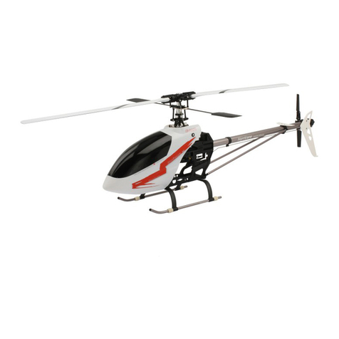
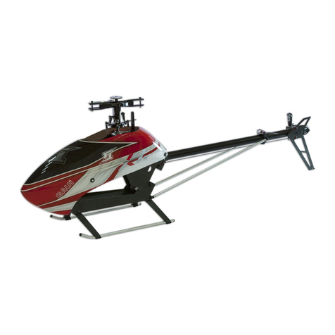
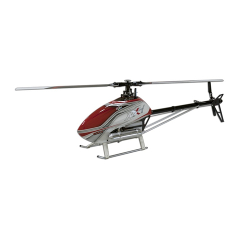
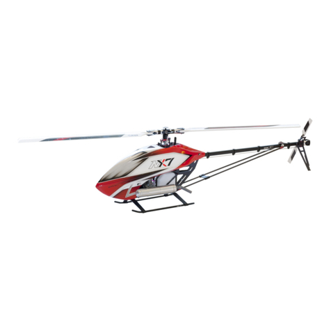
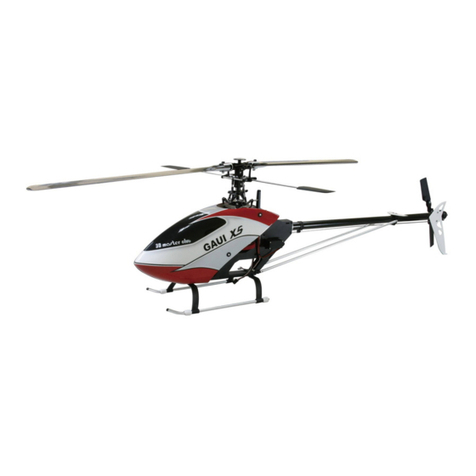
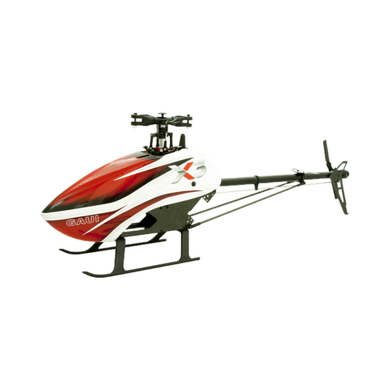
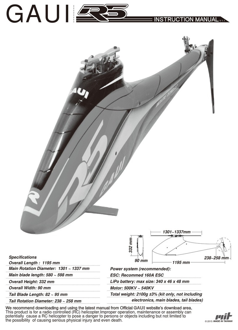
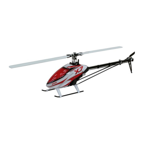
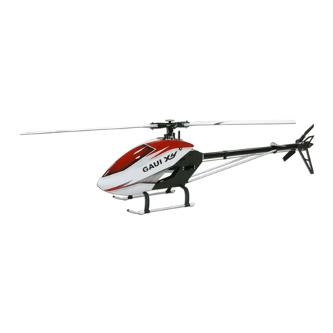
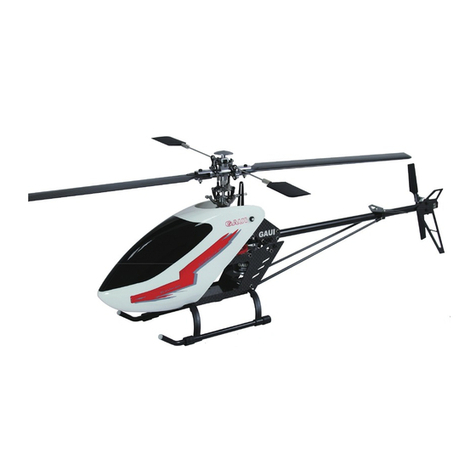
GAUI X5 User manual

GAUI
Get the latest manual:
We are highly recommending you to get the
latest version of the manual. Please visit Gaui web site to download a
copy and use that copy to replace this one.
取得最新的手冊:
我們非常建議您取得最新版本的手冊。
請到泰世網站下載最新的手冊,並且取代目前的手冊。
http://www.gaui.com.tw
ASSEMBLY INSTRUCTION

組裝代號說明
機身組立-1 & 2
機身組立-3 / 電裝配置
馬達組立
旋翼頭及十字盤組立-1
旋翼頭組立-2
旋翼頭組立-3及尾傳動軸安裝-1
尾傳動軸安裝-2
尾旋翼總成組裝
拉桿配置 / 主旋翼 / 滑軌安裝 / 基本調機設定
基本調機設定-2
主槳螺距設定
陀螺儀及EXP設定
注意事項及狀況排除
飛行前調整與說明
升級維修配件表
P.1
P.2 ~ P.3
P.4
P.5
P.6
P.7
P.8
P.9
P.10
P.11
P.12
P.13
P.14
P.15
P.16 ~ P.18
P.19 ~ P.21
Figures Instruction and Specification
Frame Assembly - 1 & 2
Frame Assembly - 3 / Electronics installation
Motor Installation
Rotor Head and Swashplate Assembly 1
Rotor Head Assembly 2
Rotor Head Assembly 3 and Shaft Driven Tail Assembly 1
Shaft Driven Tail Assembly 2
Tail Unit Assembly
Linkages / Main Blades / Swashplate Guide Assembly and TX Setting 1
Transmitter Setting 2
Collective Pitch Setting
Gyro Setting and EXP Value
Caution and Troubleshooting
Preflight Setup
Parts List
前言、安全注意事項、飛行前注意事項、組裝注意事項
Forward / Safety Precautions / Check List Before First Flight /
Notes for Assembly
Index目錄

前言
Forward
前言
Forward
安全注意事項
Safety Precautions
感謝你選購泰世科技"X5 "產品,本公司一向致力於3D電動直升機的性能提升,現今我們很榮幸能向您介紹這款最佳性能
的3D電動直升機,在進行組裝及操作之前,請務必詳細閱讀本說明書。在本說明書的介紹下您將會知道如何組裝及設定您的
"X5 "並獲致穩定及3D性能兼具的飛行特性。產品拆封前請檢視商品內容是否與標示項目及數量相符,若有零件短少或內
容物與標示不同,請於購買日起60天內洽詢原購買之經銷商。請注意!! 產品拆封後之短少或不符,以及消費者使用不當或自
行改裝產品所造成的瑕疵或損壞,將無法享有保固維修服務。任何保固維修服務之要求,需透過泰世科技公司授權之正式經銷
商或其認可之銷售通路確認後方可進行。關於產品使用及購買之相關服務請洽詢泰世科技當地經銷商或歡迎來信詢問,本公司
郵件信箱 <[email protected]>。
Thank you for purchasing GAUI “X5” product. As the industry leader and creator of the
RC helicopters, we would like to proudly introduce this ultimate machine to those who love high
performance and 3D capable ultra-micro RC helicopter, Please read all instructions thoroughly before
operation to get the best flight performance. Part or parts missing from this kit must be reported
within 60 days of purchase. No part or parts will be sent under warranty without proof of purchase.
To receive part or parts under warranty, the service center must receive a proof of purchase and/or the
defective part or parts. Should you find a defective or missing part, contact the authorized GAUI distributor
whom you bought it from. Under no circumstances can a dealer or distributor accept return of a kit if
assembly has started. This warranty does not cover any components damaged by use or modification.
1. The “GAUI X5” product is not a toy. It is a high performance model product. It is important to
familiarize yourself with the model, its manual, and its construction before assembly or operation.
Improper operations may cause personal and/or property damage. Beginner’s operating under the
supervision of the experienced pilots is necessary.
2. Do not operate model products in rain, on public roads, near crowds, near airport, or near areas with
restricted radio operation.
3. This product, its parts, and its construction tools can be possibly harmful to your health. Always
exercise extreme caution when assembling and/or operating this product. Do not touch any part of
model that rotates.
4. Use an adequate charger for the batteries and follow the instruction correctly, It is highly recommended
that use the GAUI electronic gears for this helicopter,.
5. By the act of assembling or operating this product, the user accepts all resulting liability.
GAUI and its distributor have no control over damage resulting from shipping, improper building materials,
construction, or improper usage. If the buyer is not prepared to accept this liability, then he/she return
this product in new, unassembled, and unused condition to the place of purchase.
1.泰世 "X5 "遙控直升機是一高性能飛行產品而非玩具。在組裝及操作之前請充分了解產品內容及其使用注意事項、
不當使用及組裝疏失都可能會造成操作者及週遭人員嚴重傷害或財物損失。本產品是提供給有經驗的使用者
於各合法遙控飛行場飛行,初學者請協同技術人員在旁指導,以確保飛行安全。
2.請勿在雨天及天候不佳的狀況下飛行,操作時應遠離道路、機場、及其他禁止遙控飛行器使用之區域。
3.測試時請勿接觸產品上的各項旋轉物件,飛行時應遠離運轉中的機體。
4.使用原廠電池或其他原廠建議規格之充電器、電池及電子產品並依其指示使用以確保安全。
5.產品組裝前請注意!!使用者對產品開始組裝後所之相關責任及其及疏忽所造成的意外事故須負完全責任。
本公司及其經銷商在產品售出後,對於使用者的組裝疏失、運送過程、維修不良和操作不當所發生的
意外事故均不負任何責任。
飛行前注意事項
Check List before First Flight
Notes for Assembling
1. Beginner’s operating under the supervision of the experienced pilots is necessary. It is highly
recommended that inspect the mechanism and check the setting of transmitter by experienced
pilots for first flight.
2. Check your radio frequency with the proper operating frequency of the area or country. Always check if
there are any modelers operating on the same frequency as you are. Also, check your radio for
proper operation and make sure that the power of the transmitter and receiver are sufficient before flight.
3. Make sure the mechanism of the helicopter operates smoothly without interference with each other.
4. Make sure the operating direction of the servos are correct and the servo gears work fine.
5. Make sure the connectors of the electronic gears will not be disconnected due to the vibration.
6. Make sure the parts was assembled correctly and the screws are tighten properly. Inspect the
helicopter after flight to find if there is any part was worn or broken, replace the worn parts and
ball links immediately to prevent a control failure.
7. If the Main blades or the tail blades were impacted during flight, land the helicopter immediately and
check the blades for any damage, the blades of main or tail should be replaced even if there is
only slightly impact.
1.初學者首次飛行前請由有經驗的使用者先行檢查各機構動作及遙控器設定是否正確,並協同有經驗的使用者
完成飛行調整以確保飛行安全。
2.確認遙控器頻率是否與他人相同以避免干擾,並應在動力系統連接電池前先確認遙控器功能是否正常,
並確定遙控器及接收機電量足夠該次飛行。
3.確認各機構動作是否順暢且無干涉現象。
4.確認伺服機動作方向是否正確、伺服機齒輪是否有故障或異常。
5.確認各電子設備接頭是否接合確實,避免飛行時因震動而鬆脫。
6.確認各裝備及零件已正確按裝,螺絲、螺帽、連桿並無缺少或鬆脫,飛行後另須確認各部零件是否有磨損或破裂,
過鬆的連桿或破損零件應先換新,以避免失控的危險。
7.若飛行中主旋翼或尾旋翼有碰觸地面,應立即降落並檢查機件有無損傷,旋翼產品即使是輕微碰撞亦應立即更新
以確保安全。
Do not tighten the screws too much that break the thread of parts or screws, it is necessary to use the
thread-lock or locktite adhesive for the parts or screws which indicated on manual. Recheck the
screws or nuts to make sure they are tightened and adhered properly, even for the
parts which were preassembled.
零件組裝時請依說明書指示上膠,並適度控制螺絲起子的扭力,以避免螺絲或零件滑牙造成損壞,
在裝配原廠已完成組裝之零件時,請再確認各螺絲是否確實鎖緊上膠。
組裝注意事項

P.1
#A #B #C #D #E
#F #G #H
#I #J
1234 5
67 8 9 10
每一個插圖中的代號(#A,#B,#C…1,2,3…)僅代表該插圖中的某一零件,
同一插圖中若有相同尺寸之零件,會以相同代號代表,插圖代號僅供組裝參考用。
以上圖示,於組裝時請確實注意,避免組裝後試飛造成失控零件鬆脫等情況發生。
Code Letter/Number (#A,#B,#C…,1,2,3…) used in each figure indicates the
specific part in that figure only, please refer to the parts list for the
actual item numbers. Code Letter/Number is only for the reference in assembly.
Make sure to assemble the parts as shown in figure above, incomplete/
incorrect assembly may cause the control failure during flight.
B-Bearing
B-軸承
Ø-Tap Screw
Ø-粗牙螺絲
M-Machine Screw
M-公制螺絲
P-tube
P-柱狀體
Pillar
P-柱狀體
N-Nut
N-螺母
W-Washer
W-華司
B(內徑)X(外徑)X(厚度)
Ø(外徑)X(長度)
M(外徑)X(長度)
P(內徑)X(外徑)X(長度)
P(外徑)X(長度)X(實心柱)
N(外徑)X(長度)
W(內徑)X(外徑)X(厚度)
Mark 類別 indication 標示 (mm)
B(Dia.in)x(Dia.out)x(Thickness)
Ø(Dia.out)x(Length)
M(Dia.out)x(Length)
P(Dia.in)x(Dia.out)x(Length)
P(Dia.out)x(Length)
N(Dia.in)x(Width) L-Lock nut
W(Dia.in)xDia.out)x(Thickness)
組裝代號說明
Figures instruction
規格資料
Specification
螺絲止鬆劑 上膠位置約為螺紋前端1mm寬度。
Use the thread-lock adhesive if the screws are
tightened to the metal parts.
組裝時如遇螺絲鎖於金屬件,請適量使用 螺絲止鬆劑
以確保飛行安全!
Use the thread-lock adhesive on the
tip of screw for 1mm width.
Gear Ratios 齒輪傳動比: 7.5 : 1 : 4.07 (E.M.T) Main rotor speed 2693 rpm Tail rotor speed 10960 rpm
Overall Length (with Canopy):1000Specifications 機身長度(含艙罩):1000 mm
Flybar Paddle:64x40x5mm 平衡翼尺寸:64x40x5 mm
Main Rotor Diameter:1120mm 主旋翼迴轉直徑:1120 mm
Main rotor blades:500 ~ 530mm 主旋翼長度:500 ~ 530mm
Overall Height:343mm 機身高度:343 mm
Overall Width:165mm 機身寬度:165 mm
Tail Blade Length:82mm 尾旋翼葉片長度:82 mm
Tail Rotor Diameter:235mm 尾旋翼迴轉直徑:235 mm
Flying duration: 4 ~ 5 minutes with 飛行時間: 4 ~ 5分鐘
Power System(Recommanded):
Motor -- 910KV
ESC 100A ESC
6S1P(22.2v/4200mah)
動力系統(原廠建議):
馬達 910KV
電子變速器 100A ESC
使用鋰聚電池:6S1P(22.2v / 4200mah)
Total weight: 1900g ±3% (Equipped with Blades and
all electronic gears except Battery).
全配重量:1900g ±3% (全套含電子裝備不含電池)
Gear Ratios 齒輪傳動比列表 Standard Equipment 標準配備
13T Steel Pinion Gear (E.M.T) 9.2 : 1 : 4.07 = 2195 rpm 208786 - X5 Steel Pinion Gear Pack (16T- for 5.0mm shaft)
X5 鋼製馬達齒16T(孔徑5.0mm)
14T Steel Pinion Gear (E.M.T) 8.6 : 1 : 4.07 = 2349 rpm 208903 - 61T Gear (Set of 2)
61T齒輪(2件組)
15T Steel Pinion Gear (E.M.T) 8 : 1 : 4.07 = 2525 rpm 208381 - Front drive gear set and Pulley Shaft with Steel Gear (15T)
尾傳動導輪軸(15T)附傘齒組
16T Steel Pinion Gear (E.M.T) 7.5 : 1 : 4.07 = 2693 rpm 208601 - (GUEC GM-601)Brushless Motor(1820W-910kv)
(GUEC GM-601)無刷馬達(1820W-910kv)
Tail Speed: 10960 rpm 208901 - 120T Main Gears
120T主齒盤
注 意:更改動力系統請注意電池電壓,馬達KV值及減速比 的關係來做搭配。
Improtant : The gear ratio, motor and battery should be setproperly if the power system changed!!

P.2
#A #208761
#208355
#208920
#208760
#208356
#208381
#208903
#208901
#208753
#A
#A
#B
#B
Ball Bearings Pack(8x16x5)x3
軸承(8x16x5)x3
Torque Tube Front Gear Set
尾軸傳動前齒輪組
X5 CNC Upper Servo Mount
X5 CNC上伺服機座(亮銀)
61T Gear (Set of 2)
61T齒輪(2件組)
120T Main Gear
120T主齒盤
One Way Bearing(12x18x16)
單向軸承(12x18x16)
#C
#C
Ball Bearings Pack(5x11x4)x4
軸承(5x11x4)x4
Front drive gear set and
Pulley Shaft with Steel Gear (15T)
尾傳動導輪軸(15T)附傘齒組
X5 CNC Lower Servo Mount
X5 CNC下伺服機座
#D
#E
#F
#208360 X5 One Way Sleeve Set
X5 單向鋼套
#G
#H
#I
#J
#D
#D
#E
#F
#G
#H
#J
#I
M3X6
M3X18
P3X4.8X23.5
Ø2X8
M3X6
M3X8
1.將軸承組合至 #B (1-1)。
2.組裝 #E 請將軸承確實崁入軸承孔內(1-2)。
3.組合齒盤時先將61T齒盤組至單向鋼套,再組裝120T齒盤並注意單向軸
承字體方向(1-3)。
4.主齒盤組裝完成後請務必將C型扣,扣入單向鋼套(1-4)。
請注意②.③螺絲務必鎖緊並注意不可滑牙。
1.先將(1-5)組裝完成再將上圖組裝完成的金屬件組裝
至側板。
2.③螺絲配合P.10組裝完成後再鎖緊。
注意單向軸承字體朝下
C型扣
機身組立1
Frame Assembly 1
①
②
③
④
①
②
③
④
⑤
①
①
①
①
①
①
①
①①
①
①
①①
①
①
①
①
①
②
②
③
③
④
⑤
⑤
公制六角螺絲
Socket head
machine screws
公制六角螺絲
Socket head
machine screws
公制六角螺絲
Socket head
machine screws
公制六角螺絲
Socket head
machine screws
M3X4
M3X6
公制六角螺絲
Socket head
machine screws
公制六角螺絲
Socket head
machine screws
W12.1X16.5X0.3 華司
Washer
Tube
柱狀體
①
②②②
③③
③③
④
1-5
1-1
1-2 1-3
1-4
①②③⑤
①②③
The letter-marked side
should be downward
C-Clip
1.Assemble the bearing and Uper Servo Mount(1-1).
2.Exactly assemble the bearings to the Lower Servo
Mount(1-2).
3.Assemble the one way sleeve and 61T Main Gear, assemble
the 61T Main gear Aeembly and other parts(1-3). Make sure
the letter-marked side of the One Way Bearing should be
downward.
4.After all parts in figure 1-3 is assembled, clip C-Clip to the One
Way Sleeve(1-4), make sure to tighten the screws of ② and ③.
1.Assemble the Boom Mount(1-5) and main
frame set as shown in right figure.
2. Do not tighten the screws of ③ until the Tail
Boom Assembly is assembled as shown on
page 10.
粗牙螺絲
Self taping screws

P.3
M3X6
P3X6X4
機身組立2
Frame Assembly 2
將②螺絲含上並配合下圖組裝時再將②螺絲鎖緊。
請注意安裝時需確認鋁柱中間為
3mm貫穿孔(非螺牙孔)。
#A
#A
#208362 X5 Tail Supporter Pipes
(Silver anodized)
X5 CNC支撐桿(亮銀)
①
②
③
④
公制六角螺絲
Socket head
machine screws
公制六角螺絲
Socket head
machine screws
公制六角螺絲
Socket head
machine screws
M3X6
M3X14
M3X10
M3X16
M3X3
#A
#A
#B
#B
#208970 X5 Brace Set
X5 支撐架組
Skid Set
滑橇組
#208370
①
②
③
公制六角螺絲
Socket head
machine screws
公制六角螺絲
Socket head
machine screws
Socket set screws
止付螺絲
Tube
柱狀體
①
①
①
①
②
②
②②
②
②
②
②
②
②
③
③④
①
②
②
③
③
③
③
①②
①②③
Attache the screws ② but do not tighten them
until the main frame set is assembled as in figure
below.
Install the ALU square posts
which come with 3mm middle
hole (not thread hole) onto
bottom plate.
請注意安裝時需確認鋁柱中間為
3mm螺牙孔。
Install the ALU square posts
which come with 3mm thread
hole onto battery plate.
not thread hole
A
A(x3)
B
B(x4)
非螺牙孔
3mm thread hole 3mm螺牙孔
not thread hole
A
B
非螺牙孔
3mm thread hole 3mm螺牙孔

P.4
機身組立-3
Frame Assembly 3
公制六角螺絲
旋翼頭
齒盤
Socket head
machine screws
Socket set screws
止付螺絲
Washer
華司
Nut
螺母
①①
②
③
④
1-1
1-4
1-2 1-3
電裝配置
Electronics installation
P8X13X2
M3X3
N3X5.5L
M3X16
將主軸組至機身並置入齒盤內,鎖緊③④再將主齒盤
上推並將主軸輪檔貼合上主軸板注意主軸上下不要
有間隙再鎖入①螺絲。
主軸上下不可有間隙
公制六角螺絲
陀螺儀
GYRO
接收機
Receiver
Socket head
machine screws
①
①
①
M2.6X10
安裝CCPM伺服機(1-1、1-2、1-3),伺服機配線可由外
穿入孔1並用小束帶穿過束帶孔將伺服機訊號線固定
(1-4)。
參考(1-4)將電子設備進行配置。
ESC
可使用配件包內附之魔鬼氈固定接收機、
ESC、陀螺儀。
①
①
①
②
③
④
#A
#A
#208357 X5 Main Masts(8mm)
X5 主軸(8mm)
Install the Mast and Main Gear Set, tighten the
nut ③and bolt ④, tighten the mast collar at
proper position by set screws ① to make sure
the Mast is not able to be moved up or down
after it is assembled.
For
Rotor Head
For
Main Gear Set
Make sure the Mast
is not able to be
moved up or down
after it is assembled
Install the CCPM servos as in figure 1-1/1-2
/1-3, insert the servo wires into Slot 1 and use
the cable ties to attached them as shown in
figure 1-4.
Install the electronics as shown in figure 1-4.
孔1
束帶孔
Slot 1
Slots for cable tie
Use the Touch Fastner Cable Ties to
attach the receiver / Esc / Gyro.

P.5
馬達組立
Motor Installation
公制六角螺絲
Socket head
machine screws
公制六角螺絲
切齊
Socket head
machine screws
①
②
③
③ ③
② ②
②②
M3X6
M3X10
M3X3
①
①
①
Socket set screws
Align gear edge and
motor axial end
止付螺絲
將馬達組裝至馬達板上並含上①②螺絲不鎖緊,套入
16T馬達齒並注意馬達齒需與馬達軸心切齊後
鎖緊③螺絲。
再將馬達總成置入機身調整適當間距(0.1mm),確認
間距無誤再將①②螺絲鎖緊。
公制六角螺絲
Socket head
machine screws
公制六角螺絲
Socket head
machine screws
①
②
M3X6
M3X6
調整間隙
①②③
①②
Install the Motor / Motor Mount / 16T Pinion gear
but do not tighten the screws ①② , tighten the
set screws ③and make sure to align the gear
edge and motor axial end, then adjust the gear
mesh properly( it is about 0.1mm ) and tighten
the screws ①② .
Adjust the gear mesh properly.

P.6
旋翼頭及十字盤組立-1
Rotor Head and Swashplate Assembly 1
W3.1X4.6X0.6
組裝相位器總成,十字盤總成。
公制六角螺絲
Socket head
machine screws
Pillar
柱狀體
①
②
③①
③
②
①
③
④
④
②
#A
#A
#A
#B
#B
#C
#C
#C
#C
Bearing(3x6x2.5)x4pcs
軸承包(3x6x2.5)x4個
Stainless (4.8mm)
不銹鋼(4.8mm)球頭組
Stainless (4.8mm)
不銹鋼(4.8mm)球頭組
#208759
#208782
#208783
M3X10
P2X10
華司
Washer
W3X6X0.5
N3X5.5L
華司
Washer
1.將十字盤總成、相位器總成、旋翼頭依序置入
主軸內鎖緊①螺絲。
2.將相位器推桿扣上十字盤。
公制六角螺絲
Socket head
machine screws
①
②
③
④
#A #A #A
#208912 Head Spacer & Damper Set(95)
橫軸橡皮墊(硬度95)
M3X16
螺母
Nut
P2X23 柱狀體
Pillar
①
Assemble the Swashplate and the Washout Arms
and base Assembly.
1.Install the Swashplate / Washout Assembly /
Rotor Head and tighten bolt ①as shown.
2.Attach the Radius arms onto swashplate.

P.7
公制六角螺絲
Socket head
machine screws
①①
①
#A
#A
#A
#B
#B
#C
#C
#C
#208758 Flange Bearing(3X8X4)
法蘭軸承(F3X8X4)
Bearing(B3x6x2.5)x4pcs
軸承包(B3x6x2.5)x4個
Stainless (4.8mm) Balls
不銹鋼(4.8mm)球頭組
#208759
#208782
M3X7
將平衡桿座組裝至旋翼頭再鎖上球頭與①螺絲。
①
②
③
④
⑤
⑥
⑤
①
①
①
②
②
②
③
④
④
#A
#A
#B
#B
#C
#C
#D
#D #E
#F
#208752 Ball Bearings Pack(6x13x3.5)x4
軸承(6x13x3.5)x4
Thrust Bearings(T6x12x4.5)x4
止推軸承包(T6x12x4.5)x4
X5 Spindle Shafts
X5 橫軸
X5 CNCMain Grip Set
X5 CNC主旋翼夾頭
Ball Bearings Pack(6x13x5)x4
軸承(6x13x5)x4
X5 CNC Main Grip Levers
X5 CNC主旋翼夾頭舵柄
#208755
#208345
#208751
#208343
#208346
#E
#F
Washer
華司
Washer
華司
Washer
華司
W4.1X10X1.4
W6.2X7.6X0.5
W6.1X10X1.5
公制六角螺絲
內徑(大)
Socket head
machine screws
Bigger inner race
內徑(小)
Smaller inner race
M4X10
M3X7 公制六角螺絲
Socket head
machine screws
公制六角螺絲
Socket head
machine screws
M3X10
將主旋翼夾頭組裝至旋翼頭並注意軸承方向再將
煞車盤組裝至旋翼頭。
⑥
①
①⑤⑥
Assemble the Crosstube and balls and tighten
the screw ①as shown.
Assemble the Main Rotor Grips and The Stop
Plate.
Make sure the Thrust Bearing should be installed
correctly as shown in figure.
旋翼頭組立-2
Rotor Head Assembly 2

P.8
公制六角螺絲
Socket head
machine screws
Socket set screws
止付螺絲
Washer
華司
①
②
③
④
#A
#A
#A
Bearing(3x6x2.5)x4pcs
軸承包(3x6x2.5)x4個
#208759
#B
#B
#B
Stainless (4.8mm) Balls
不銹鋼(4.8mm)球頭組
#208782
#C
#C
X5 Flybars Pack(400mm)
X5 平衡桿包(400mm)
#208349
W3.1X4.6X0.6
M4X4
Socket set screws
止付螺絲
①
①
①
M3X3
M3X6
公制六角螺絲
Socket head
machine screws
M3X10
將旋翼搖臂組裝完成(1-1)並組裝至主旋翼夾頭舵柄。
安裝平衡系統夾片並對照下圖調整平衡桿間距在鎖緊
③螺絲。
137.5mm
161mm 161mm
137.5mm
①
②
②
③
③
④
尾傳動軸安裝-1
Shaft Driven Tail Assembly 1
#A #A
#B #208909 X5 Torque Tube Drive Gear Set
X5 尾軸傳動齒輪包
#B
#208920 Torque Tube Front Gear Set
尾軸傳動前齒輪組
#C
#C
#D
#D
#208763
#208762 Ball Bearings Pack(8x14x4)x3
軸承(8x14x4)x3
Ball Bearings Pack(12x18x4)x3
軸承(12x18x4)x3 平面
CA
請注意傘齒輪平面需貼合軸承平面。(1-1)
組裝時請將軸承崁入尾傳動軸承墊圈組,再上膠
於軸承與墊圈接合處,上膠時請小心勿接觸到軸承
內緣,再套入橡皮墊圈。(1-2)
1.The flat surface of the bevel gear should touch the
inner race of the bearing as shown in (1-1).
2.When assemble the bearing into the bearing mount,
make sure not to glue the CA to the balls of bearing.
Install the O ring as shown in (1-2).
1-1
1-1
1-2
②③④
①
Assemble the Mixing Arms as shown in 1-1,
Assemble the Flybar Cage and adjust the Flybar
properly to make it come with equal length in
both sides, tighten the set screws ③as shown.
Flat surface
旋翼頭組立-3
Rotor Head Assembly 3

P.9
①
②
③
③
③
③
④
⑤
⑥
⑥
M3X5
M3X6
Ø2X8
#A
#A
#A
#208763 Ball Bearings Pack(12x18x4)x3
軸承(12x18x4)x3
#B
#B
#208380
Tail Output Shaft and
bevel gear set
尾軸附傘齒組
#C
#C
#C
#208754 Flange Bearing(5x10x4)
法蘭軸承(5x10x4)
①
②
③
④
⑤
⑥
⑦
公制六角螺絲
Socket head
machine screws
M3X4 公制六角螺絲
Socket head
machine screws
公制六角螺絲
Socket head
machine screws
M3X10
公制六角螺絲
Socket head
machine screws
粗牙螺絲
Self taping screws
W3.1X5.5X1.1 華司
Washer
P3X4.8X20 柱狀體
Tube
P2X12
W3.1X5.5X1.1
#A
#A
#208369 CNC Tail Pitch Slider Set
(for 5mm tail output shaft)
CNC螃蟹夾組(5mm尾軸用)
#B
#B
#B
#208907 Tail Pitch Control Lever Set
尾舵角片
#C
#E
#C
#E
#D
#208363 X5 Tail Hub
X5 CNC尾旋翼頭
#D
#208765 Ball Bearings Pack (4x7x2.5)x4
軸承(4x7x2.5)x4
#E
#208764
利用滑套旋入組合尾螺距推桿座並組合推桿(1-1)。
2.Assemble the tail pitch control lever and
install it onto tail gear case(1-5).
將組合完成的尾螺距推桿座套入尾橫軸內並組合
尾舵角片及尾旋翼頭(1-2)。
1.Assemble the Tail Slider Bush into pitch
yoke as shown in (1-1).
①
②
③
④
⑤
⑥
⑦
M3X3
M3X18
P5X6X18.5
華司
Washer
N3X5.5L 螺母
Nut
Pillar
柱狀體
Ball Bearings Pack(6x10x3)x2
軸承(6x10x3)x2
①
①
②
③
③
④
⑤
⑥
⑦
Socket set screws
止付螺絲
公制六角螺絲
Socket head
machine screws
Tube
柱狀體 fixing end for screws
固定孔
P3X4X9.5 Tube
柱狀體
1-1
1-2
⑦
⑦
①②③⑤⑦
③
尾傳動軸安裝-2
Shaft Driven Tail Assembly 2

P.10
尾旋翼總成組裝
Tail Unit Assembly
#A
尾管夾
拉桿座
將傳動軸插入尾管總成內並套入尾管夾及拉桿座。
Insert the torque assembly into the tail boom, install
the Pushrod Control Guide & Tail Support Clamp as
shown in figure.
W4.1X6X0.5 華司
Washer
N3X5.5L
M3X16
Ø2X8
P2X2.95X4.3
#A
#A
#A
#B
#B
#A
#208756 Ball Bearings(4x9x4)x2
軸承(4x9x4)x2
#B
#C
#208757 Thrust Bearings(T4x9x4)x2
止推軸承包(T4x9x4)x2
#C #208908 Tail Rotor Blade Set(82mm)
尾旋翼(82mm)
①
②
③
④
⑤
#A #208367 X5 Torque Tube Tail Boom Assembly
X5 CNC軸傳動尾管總成
公制六角螺絲
Socket head
machine screws ①
①
①
②
②
③
④
⑤
Nut
螺母
粗牙螺絲
Self taping screws
Tube
柱狀體
M3X12
組裝尾管總成並鎖緊①、②螺絲。
①
②
①
公制六角螺絲
Socket head
machine screws
N3X5.5L 螺母
Nut ②
M3X6
Ø3X8
①公制六角螺絲
Socket head
machine screws
粗牙六角螺絲
Self taping
machine screws
1.將尾管總成置入機身並仔細調整尾管總成與動傘
齒輪的間隙(不可過緊或過鬆),再鎖緊P.2 ③螺絲。
2.鎖緊時請保持垂直尾翼與機身垂直。
並將尾舵拉桿穿過尾管夾、拉桿座。
①
①
②
②
尾舵拉桿
③
①②③
內徑(大)
Bigger inner race
內徑(小)
Smaller inner race
Assemble the Fin and Tail Gear Case Assembly
onto Tail Boom and tighten the screws ①and ②.
1.Insert the the Tail Boom Assembly into Main
Frame, adjust the gear mesh properly and
tighten the screws ③ as shown in Page 2.
2.Make sure the tail pushrod was installed
before inserting the Tail Boom Assembly into
Main Frame, the Fin should be installed
vertically.
Tail Pushrod
Pushrod Control Guide
Tail Support Clamp
②

拉桿配置/主旋翼/滑軌安裝
Linkages / Main Blades / Swashplate Guide Assembly
基本調機設定
Transmitter Setting
1.請先拔掉電子變速器與馬達連接的三條線中的
任兩條。(避免調機過程馬達啟動而造成危險)
2.設定遙控器選單中,【模型類型】選項為
直昇機模式(HELI)。
3.設定遙控器選單中【十字盤類型】選項
JR 請選擇(120度)
FUTABA 請選擇(HR3)。
警告:
高功率的馬達系統是非常危險的,高電流能加熱電線和電池導致火災或燙傷皮膚,
請跟著指示說明小心使用,配有高功率馬達的遙控模型會造成傷害,一定要在標準的飛行場,
並且不能穿越或接近人群,即使你已經有了安全的配套措施,當你連接上電池你還是必須要小心操作。
65mm
88.2mm
#C
#C
#D
#D
23.5mm
50.6mm
#D
#208401
#208906s
#A
#A
#B
#B
#208904
#208905
組裝主旋翼拉桿及伺服機擺臂並將拉桿組裝至十字盤。
組裝滑軌及主旋翼。
Double Link(L-30)
L-30拉桿
Double Link(L-35)
L-35拉桿
Thread Rod for CCPM
CCPM螺桿組
Ball Links Pack
拉桿頭
①
②
③
④
⑤
⑥
⑦
公制六角螺絲
M2X12
N2X4
Socket head
machine screws
M2X8
M2X5
公制六角螺絲
M4X23 Socket head
machine screws
公制六角螺絲
Socket head
machine screws
公制六角螺絲
Socket head
machine screws
螺母
Nut
N4X7L 螺母
Nut
W4.2X8x0.5 華司
Washer ①
②
②
4.先開啟發射機電源再開啟機體電源。
5.將油門搖桿撥動至中立50%的位置。
開啟發射機電源 開啟機體電源
④
③⑤
⑥
機首 機尾
P.11
將油門搖桿撥動至中立的位置。
⑦
①③④
1.Disconnect the motor wires before setting the
transmitter function.
2.Set the transmitter function “Model Select” to
“Heli Mode”.
3.Set the transmitter function “ Swash Plate
Type ” to “ HR3 ” for Futaba transmitter.
Set the transmitter function “ Swash Plate
Type ” to “ 120 ” for JR transmitter.
Caution!!
High power motor systems could be very dangerous.
High current could generate heat on wires, batteries, and motors.
Always follow the instruction and use proper tools to set up the system within safe range.
Always fly at a designed field with caution even though this controller is equipped with safety arming program.
Swith on the transmitter power
Install the Linkages / Servo Horns / Swashplate
Guide / Main Blades as shown in figure.
Front Rear
。
4.Switch on the power of transmitter first and
then the receiver power.
5.Move the throttle stick to middle position.
( Neutral position at value 50% )
Swith on the receiver power Move the throttle stick to middle position
( Neutral position at value 50% )

P.12
7.油門搖桿上推,確認連接3顆伺服機的十字盤是否同時向上移動,若無同時向上移動,請至搖控器選單設定
【伺服機正反向設定】選項更改動作相反的伺服機使十字盤同時向上移動。
8.向右撥動副翼搖桿,確認十字盤是否向右傾斜,若無向右傾斜,請至遙控器選單中SWASIA選項內的AILE(副翼)的%數更改為負值。
◎適當的增減數值可調整AILE動作量大小。
9.向前撥動升降搖桿,確認十字盤是否向前傾斜,若無向前傾斜,請至遙控器選單中SWASH選項內的【ELEV】升降的%數更改為負值。
◎適當的增減數值可調整ELEV動作量大小。
10.將油門搖桿撥動至中立50%的位置。
6.以90o扣上伺服機舵片扣上舵片時會因伺服機齒輪差異
而無法垂直90度)請確認十字盤動作方向無誤後,再參
照以P.13,第11項【伺服機微調選項的 "Subtrim "
功能】進行中立點微調。
90o
6.Set the transmitter function “ Subtrim ” to adjust
the neutral position of CCPM servos, the servos
at neutral should have the servo arms at level
position, and each arm should be perpendicular
to the control linkage. ( Refer to the Step 11 in
page 13 )
7.Move the throttle stick upward, check and make sure 3 linkages of swashplate are all moved upward,
set the transmitter function “ Reverse ” to reverse the operating direction if any one of the CCPM servos
them is not moved correctly.
Mode 1 Mode 2
8.Move the AIL stick rightward, check and make sure the swashplate tilt to right side, if it tilt to the opposite
side, set the “AIL %” in transmitter function “ Swash Mix ” to Negative value to make the swashplate move
as your control. ( Ex. Set the “AIL +50%” to “AIL -50%” )
◎Increase or decrease the “AIL %” to get the proper response of the AIL control.
9.Move the ELE stick forward, check and make sure the swashplate tilt forward, if it tilt to the opposite side, set the
“ELE %” in transmitter function “ Swash Mix ” to Negative value to make the swashplate move as your control.
( Ex. Set the “ELE +50%” to “ELE -50%” )
◎Increase or decrease the “ELE %” to get the proper response of the ELE control.
10.Move the throttle stick to middle position
( Neutral position at value 50% )
基本調機設定-2
Transmitter Setting 2
Mode 1 Mode 2
Mode 1 Mode 2

P.13
主槳螺距設定
Collective Pitch Setting
Horizontal
水平
Horizontal
水平
90o
90o
Horizontal
水平
Horizontal
水平 ①
①
11.至遙控器選單中的【伺服機微調選項的 "Subtrim "
功能】將十字盤3顆伺服機擺臂微調至垂直90度。
12.請將油門搖桿撥至中立,以螺距尺測量主旋翼的度數
是否為0度。 若不是0度,請調整①號連桿長度使2支
主旋翼均為0度。
13.調整3顆伺服機連桿長度至十字盤、相位器、日字框、
平衡翼皆水平。
14.請將油門搖桿向上撥至最高,測量主旋翼最大【正】螺距度數,應為+11至+13度。
若不是,請調整遙控器選單中【SWASH】內的【PIT】數值。
請將油門搖桿向下撥至最低,測量主旋翼最大【負】螺距度數,應為-11至-13度。
【正】【負】螺距度數需一樣若不是,請調整遙控器選單中的【伺服機大小行程量】
數值,三顆伺服機需同時增加或減少至測量結果與正螺距度數相同。
螺距量角器與平衡桿需水平
15.請將油門搖桿撥至最低點,測量主旋翼【負】螺距度數約在-2至-3度,並請進入遙控器
選單中【PITCH曲線設定】選項,至【NORM模式】中增加數值最低的數值,使主旋翼
【負】螺距度數約在-2至-3度。
【設定完的數值大約在40%至45%之間】至曲線設定中間的數值,增加數值至55至60%
◎進行第15項時請、上、下、左、右、前、後撥動搖桿,查看十字盤
行程動作是否有干涉。若有干涉請至SWASH減少AILE、ELEV數值。
螺距量角器與平衡桿需水平
螺距量角器與平衡桿需水平
11.Set the transmitter function “ Subtrim ” to adjust
the neutral position of CCPM servos, the servos
at neutral should have the servo arms at level
position, and each arm should be perpendicular
to the control linkage.
The bottom edge of the
Pitch Gauge should be
paralle to the Flybar
The bottom edge of the
Pitch Gauge should be
paralle to the Flybar
The bottom edge of the
Pitch Gauge should be
paralle to the Flybar
12.Move the throttle stick to the neutral (middle at 50%
value), use a pitch gauge to check the pitch of both
blades, adjust the linkages ①to make sure they are
all in 0 degrees of both blades.
13.The Servo Horns / Swash
Plate / Washout Arms / Flybar Paddles and Cage
should be set to be horizontal as shown in figure.
14.Move the throttle stick to the top position, the maximum
positive pitch should be around +11 to +13 degrees,
set the proper “Pitch %” in transmitter function “ Swash
Mix ”.
Move the throttle stick down to the bottom position, the
maximum negative pitch should be around -11 to -13
degrees, set the transmitter function “ Travel Volum /
End Point “ properly to make it come with recommended
negative pitch.
IMPORTANT : The increase/decrease value of the
transmitter function “ Travel Volum / End Point “ of each
CCPM servo should be the same in this step.
◎ Before starting the step 15, make sure to move the control
sticks to check the movement of the swashplate and set the
proper “AIL % and ELE %” in transmitter function “ Swash
Mix ” to make sure each mechanism is not interfered
with each other.
15.Move the throttle stick to the lowest position, set the proper “ Pitch Curve % ”
in transmitter function “ Normal Mode ” to make the negative collective pitcht
to be -2 or -3 degrees at the lowest throttle stick position( it is about 40% to
45% at the 1st pitch curve point at normal mode). The value of the middle
point of pitch curve in normal mode is about 55% to 60%.

P.14
陀螺儀及EXP設定
Gyro Setting and EXP Value
17.請至遙控器設定選單中【陀螺儀感度GYRO】至鎖定狀態,
向右撥動尾舵搖桿,尾軸滑套須向尾齒箱移動,
若不是請調整遙控器選單中【伺服機正反向設定】
選項中【RUDD】的正反向。
18.將機尾朝向自己,以機體為軸心慢慢以畫圓的方式移動機尾向右,此時尾軸滑套需向尾齒箱移動並修正,若不是,
請更改陀螺儀正反向設定。【各廠牌陀螺儀設定方法不同,請參照陀螺儀使用說明作設定】。
19.設定尾舵左右最大行程量,左右最大行程量保持與尾齒箱及尾旋翼頭0~0.5mm距離不干涉為主。
(各廠牌陀螺儀行程量設定方法不同請參照陀螺儀說明書作設定)。
20.請設定遙控器選單中EXP的感度指數,各數值設定如下: AILE 30~50% ELEV 30~50% RUDD 50~70%。
JR請以【正】數值設定、Futaba請以【負】數值設定
21.關閉機體電源與發射機電源,將四顆伺服機擺臂螺絲鎖上
尾齒箱
尾軸滑套
16.調整陀螺儀至非鎖定狀態下,將尾舵角片垂直於尾管,
在將伺服器擺臂扣上伺服器並保持擺臂垂直90度。
90o
16.Set the gyro to non-heading-hold mode, attach the
tail servo horn and set it perpendicular to the tail
pushrod.
17.Set the gyro to heading-hold mode, move the rudder
stick rightward and make sure the tail pitch slider
move towardward to the tail gear case, if it is not, switch
the transmitter function “ Servo Reverse ” of “ Rudder” to
the opposite position.
18.Put the heli tail toward to yourself (Heli nose forward), move the tail to right side (Heli nose moves
leftward), the gyro should control the tail servo to move the tail pitch slider toward to the tail gear
case, if it is not, switch the “ gyro direction switch ” to the opposite position. The way of setting may
vary due to the different gyro brands.
Tail Pitch Slider
Tail Gear Case
19.Set the “ Limit ” on your gyro properly to have the maximum travel of tail pitch control, make sure the
tail pitch slider at its maximum travel to left and right should not touch the Tail Gear Case and Tail Hub,
there should be a distance for 0.5mm( or less ) at each side. The way of setting may vary due to the
different gyro brands.
20.Set the “ EXP Value ” in transmitter function as follow recommendations :
“ AIL 30% to 50% ” / “ ELE 30% to 50% ” / “ RUD 50% to 70% ” , or set
them properly by yourself after few flights.
Set the “ EXP ” values in Positive for JR transmitter, and set them Negative for Futaba transmitter.
21.Switch off the power of receiver and transmitter, tighten the screws of each servo horn after power off.

P.15
Caution and Troubleshooting 注意事項、狀況排除
1.起飛時尾部左右快速擺動,或起飛後尾部不定時快速擺動: 排除<1>陀螺儀感度過高,減少陀螺儀感度數值。
請維持良好習慣: X-5 電動遙控直升機為高科技精密零組件構成之休閒用品,玩家請時常注意確保機體的保養及維持
機構組件之性能,於飛行時展現其優異的性能,不當的保養維護,會導致飛行時的安全度降低。
初次起飛前請再次確認各部位動作是否正確,並向有經驗之飛友確認設定是否正確。
主旋翼運轉發生異常時,請檢查主旋翼、橫軸;主軸是否有變形或平衡不良,必要時請更新異常機構零件。
飛行時不慎觸地,請優先檢查旋翼頭零件及橫軸螺絲、混控臂、平衡桿等。
皮帶:長期運轉會使皮帶造成老化、斷齒等狀況為了維護飛行安全請更換新品。
停旋:主旋翼轉速偏低,請注意主旋翼的PITCH是否偏高或停旋點油門曲線過低。
停旋:主旋翼轉速偏高,請注意主旋翼的PITCH是否偏低或停旋點油門曲線過高。
主軸軸承:主軸軸承經長期負載運作,正常飛行約100趟後必須檢查各部機構、軸承性能狀況,
如有異常請更換新品以保持運作順暢。
如經常進行3D飛行或嚴重撞擊,建議你必須時常檢查機構、零件、軸承等,如發現異常狀態或間隙、異音或是轉動
有明顯干涉等都必須更換新品。
單向軸承飛行50趟後請卸下來清潔與重新上油。
The X-5 heli product is not a toy, for the consideration of safety and performance, it is necessary to
check and maintain after each flight.
When spinning, if the blades are unbalanced or the tracking of both blades is not even with each other, Check or
replace the Blades / Mast / spindle shaft to fix the problem.
Check the mechanism and bearings after 100 normal flights for safety.
Check and replace the damaged parts after crash of hard 3D flight.
When hovering, decrease the collective pitch or adjust the hovering throttle curve higher if the head speed is too
slow, increase the collective pitch or adjust the hovering throttle curve lower if the head speed is too high.
Check the Rotor head assembly / main grip screws / mixing arms / flybar after crash (even in slightly compact),
replace the damaged parts before next flight.
Remove the one way bearing after 50 flights, clean it and grease it with oil.
Replace the belt if there is any fissure on it.
【Troubleshooting 狀況排除】
【Caution 注意事項】
2. 起飛後尾部向某一方向偏移: 排除<1> 請關機後重新開機。
在開啟後直升機電源時勿移動或晃動到直升機,須待陀螺儀鎖定後才可移動,過程約1~3秒。
若開機後在陀螺儀尚未鎖定前不小心移動或晃動到機身而使陀螺儀中立點搜尋不正確,
可能會造成尾部向某一方向偏移的狀況。
排除<2> 檢查尾陀中立點是否正確。 ※參照P.14,第19項重新設定。
排除<3> 陀螺儀感度設定過低:需調高陀螺儀感度。
3. 雙槳: 排除<1> 在調整主旋翼0度時不夠準確,需重新調整。※參照P.13,第12項重新設定。
排除<2> 將其中一支主旋翼的尾端做上明顯記號,在停懸時查看有做記號的是在上或下。
在上,請減短連桿長度。
在下,請增加連桿長度。
4. 停懸時機身前後晃動: 排除<1> 油門停懸點曲線設定過低,增加設定值進入THRO CURV。
在NORM的設定畫面中,增加中間的數值,慢慢增加至狀況排除。
排除<2> PICTH停懸點曲線設定過高,減少設定值。
進入PIT.CURV。
在NORM的設定畫面中,減少中間的數值,慢慢減少至狀況排除。
5. 直升機在起飛過程中尚未離地時快速自旋: 排除<1> 陀螺儀修正正反向錯誤。
請參照P.14,第18項重新設定。
6. 若以上都未能排除之狀況,請聯絡專業人員為您排除與解說。
For the first flight, it must be under supervision by an experienced pilot to check the mechanism and
transmitter setting before flying.
1. The tail wags in hovering or flying :
(1) Decrease the gyro gain value in transmitter.
2. The tail drifts to one side in hovering or flying :
(1) Switch off the receiver power and switch on again but do not move the heli after 1 to 3 seconds or wait until the gyro LED indicates
it is Heading hold mode.
(2) Chech the neutral of tail servo or reset it as shown in step 19 on page 14.
(3) Increase the gyro gain value in transmitter.
3. The improper main blade tracking :
(1) Reset the pitch of each blade as shown in step 12 on page 13.
(2) Adjust the grip linkages properly to make both blades in the same tracking.
4. The heli shakes in hovering :
(1) Increase the head speed by setting the transmitter function “ Throttle Curve ” to higher values in middle section of the curve.
(2) Decrease the hovering pitch by by setting the transmitter function “ Pitch Curve ” to lower values in middle section of the curve.
5. The heli spins before take off :
(1) Reverse the gyro direction as shown in step 18 on page 14.
6. Enquire for an experienced pilots to check it in person in case you are not able to fix the problem which you occured.

P.16
飛行前調整與說明
Preflight Setup
For beginners, it is highly recommended to use the simulator at beginning.
For beginners, it is highly recommended to use the training gear.
Make sure to check that your frequency is not interfer with others in the same field.
Make sure the throttle stick is at the lowest
position and turn on the power of transmitter. Turn on the power of receiver.
Make sure to keep away from the spinning blades when tracking them.
1. Mark on the tip of one blade.
2. Increase the throttle little by little to check the tracking.
3. Adjust the linkage of one Main Grip if both blades is not even with each
other when spinning.
4. Adjust Pitch linkages properly for a good tracking.
The heli will be unstable if the tracking is not set properly,
especially for the heli with FES rotor head.
The collective pitch for hovering is 5 or 6 degrees approximately in normal mode.
Simulator 請事先熟練模擬飛行
示意圖
Real flight 實機飛行
Blade Tracking
主旋翼雙槳平衡調整
調整主旋翼雙槳時請保持安全距離。
1.調整前請在其中一支主旋翼的翼端,畫上明顯記號或貼有色貼紙,方便調整時辨識。
2.慢慢推起油門桿,直升機離地前從側邊側視觀察直升機主旋翼雙槳。
3.注意雙槳轉動時產生的軌跡,雙槳軌跡相同則不需調整,如遇不同軌跡請立即調整。
4.調整螺距連桿使雙槳軌跡相同。
主旋翼轉動時高軌跡代表主旋翼PITCH過大請調短1號連桿使PITCH一致。
主旋翼轉動時低軌跡代表主旋翼PITCH過小請調長1號連桿使PITCH一致。
過高的軌跡容易使電池與馬達產生過熱現象。
過低的軌跡容易造成浮力不足耗電量增大。
飛行時軌跡不一致會產生振動造成飛行上的不安定,
如為FES機時請仔細調整。
調整完成後請確認 Normal 狀態之停旋Pitch角度約+5 ~ +6。
初學者請事先熟悉遙控器操作並能熟練的反應各動作,再實機飛行。
建議透過市售販賣模擬軟體進行模擬器練習如此提高飛行安全、降低損耗,以增加實機飛行的樂趣。
初學者實機飛行前建議加裝練習腳架,可避免初次上機因緊張、壓力等因素造成不等的損害,
初次飛行時請勿離地過高,一驚覺有危險請將油門推至低點,練習腳架可預防重心不穩、
輕降落等問題降低對機身的損害。
並持續練習油門手感到操縱自如後再練習副翼跟方向舵。
請先確認該飛行場地是否有其他遙控型飛機的飛友,如有請向對方確認彼此之間的頻率,並向對方告知自己所用之頻率,
以避免相同頻率互相干擾造成損害。
將發射機電源開啟,油門搖桿推至低點。 接上直昇機電源
Landing immediately when the power
is not enough when hovering, replace
a battery before next flight.
當飛行感覺出力不穩時請更換電池,
關上電源時請依上述操作反執行
Mode 1 Mode 2
Training gear 初學者建議加裝練習腳架
Other manuals for X5
1
Table of contents
Other GAUI Toy manuals
Popular Toy manuals by other brands

Jamara
Jamara E-Rix 450 instruction manual

Cranium
Cranium Giggle Goggles instructions

Faller
Faller CAMPING-BASIS-SET manual

Melissa & Doug
Melissa & Doug AnimalCare ActivityCenter Assembly instructions

Fisher-Price
Fisher-Price Soft Slumber Campground wonder makers GFJ10 Decision maker's guide

Eduard
Eduard A-26B Invader seatbelts STEEL manual