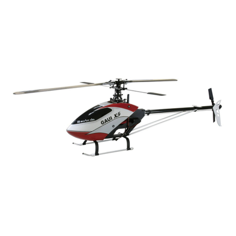
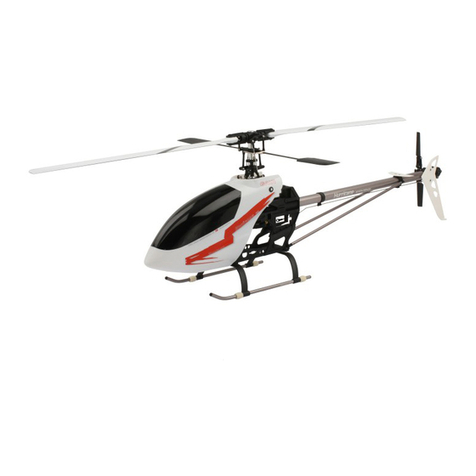
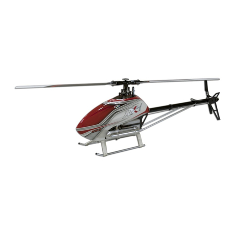
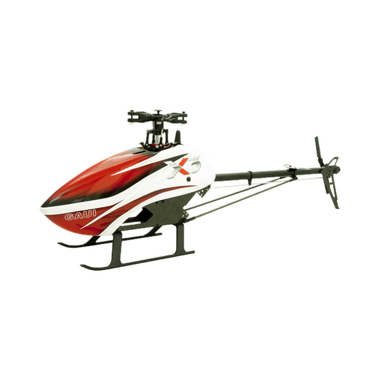
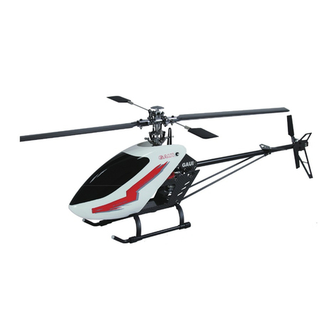
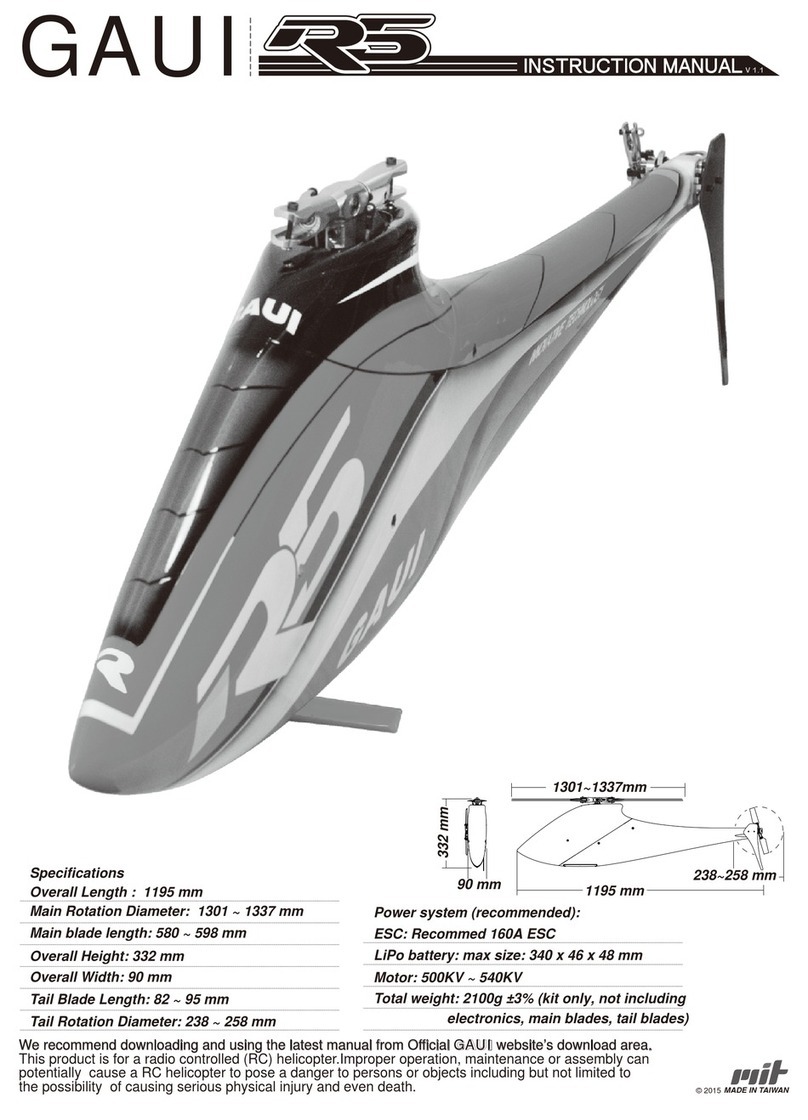
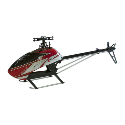
GAUI Hurricane EP200 V2 Series User manual

Equipment Recommendations :
1. Transmitter : 6 Channel or more ( CCPM-Capable )
2. Receiver : Micro Receiver 6 Channel or more ( NO : 921601 ~ 3 )
3. Servos : BMS 306BB 6g Servos ( NO : 922601 ) or 9g Servos as the
same size for EP400 class heli
4. Motor : 7.4V ~ 11.1V BL-Motor KV-4800 ( NO : 203501 )
5. Battery : Li-Po 7.4V ~ 11.1V 800mah ( NO : 926080、926081 )
6. ESC : 18A Micro ESC ( NO : 923182 )
7. Gyro : GU210 Heading Hold Gyro ( NO : 924210 ) for Hurricane200V2 SE
or GU365 FES 3-Axis Gyro ( NO : 924365 ) for Hurricane200V2 FES
8. Main Blades : SP Blades or Wooden Blades ( NO : 203308、203306 )
9. Flying Weight : 300g 10 % ( Depending on Equipment Used )
Hurricane EP200 V2 Series Instruction Manual
GAUIHobby
105
148.5

Electronics installation and wiring
Tail servo and the heading hold gyro setup
Servo and Linkage Installation
Pitch settings
Head speed and pitch settings
Main Rotor Head Assembling
Main Fram Assembling
Double Joints Tail Slider & CNC Tail Gear Case Assembling
Belt Driven Unit Assembling
Shaft Driven Unit Assembling
ESC instruction
Specifications of Motor and ESC
GU-365 FES Gyro installing
FES 2Blade Head & Swashplate Assembling
Optional & Replacement Parts
Specification of Screws
1
2
3
4
5
6-7
8-9
10
11-12
13-14
15
16
17
18
19-24
25
105
148.5

CH-1
CH-6
6ch FM
1
2
3
5
6/B
4
Racng Team
3-6 LiPo Cells
18A ESC
Heading Hold
Gyro ( GU-210 )
Tail Servo
Battery
Receiver
( S ) Gyro
Sensitivity
Tail Servo
plug into
Gyro
Micro Receiver (6CH)
Motor
Charging
plug
Servo
(ELE)
Servo
(PIT)
Servo
(AIL) ESC
Battery
To Receiver CH4
Servo
(AIL)
Servo
(PIT) Servo
(ELE)
Heading Hold
Gyro ( GU-210 )
To Receiver
CCPM
(Swash plate)
Electronics Installation and Wiring
Gyro Socket
(AIL)
(ELE)
ESC
GYRO
Gyro Gain Plug(S)
(PIT)
(RUD)
ESC
(AIL)
(ELE)
GYRO
Gyro Gain Plug(S)
(PIT)
(RUD)
FUTABA HITEC JR Sanwa Blue ESC GYRO
To Receiver CH5 or Ch7
(S)
(+)
(-)
Bird
CH
1
CH 2
CH 3
CH 4
CH 5
CH 6
Signal White Orange Orange Blue
Orange
Orange
White Yellow
Positive Red Red
Red Red Red
Red
Red
Negative Black Black
Brown Black
Brown
Brown
Black

Tail servo and the heading hold gyro setup
1. Install the Gyro and the tail servo.
2. Connect the tail pushrod to the servo.
Make sure the servo arm is 90 degrees
to the tail pushrod. The ball link
should be set at the second hole on
the servo arm (as shown on left).
3. Slide the servo mount and the tail
servo along the tail boom until the
tail pitch lever is parallel to the
tail output shaft or slightly forward.
Important:
Do not touch the
tail pitch lever
mount and the
tail rotor hub.
4. Set the Gyro limitproperly, make sure the
tail pitch yoke do not touch the tail pitch
lever mount and the tail rotor hub when the
tail servo moves to the left and the right
maximum travel volumn. If the Gyro you used
do not have the function of Limit , set the
function of ATV / End Point / Travel Adjust
on transmitter to adjust the proper travel
volumn of the tail servo.
5. If the tail oscillates or wags at less than 60%
gain,you will need to move the ball link to the
hole which is closer to the serve Gyro limit
properly. The ideal gain setting is around 70%.

L1 L2 L3
L4 L5
L
1
L2
L3
L4
L5
30.5 mm 31 mm 25.5 mm 37.7 mm 35.3mm
Servo and Linkage Installation
Rotate each blade clockwise until
the blades are parellel to the flybar.
(Top View)
Slide the swashplate up or down until
the blades are parallel to the flybar (Left
View). The collective pitch angle is zero
at this position.
Length of each linkage
Servo and linkage setting
1.
Adjust the length of the control linkages
as figure below. Make sure that the the
servo arms for CCPM swashplate
are all in the same length.
2.The servos at neutral should have the
servo arms at level position, and the
arm should be 90 degrees to the
control linkage. At this point,the
swash plate and the scissor
arms should be level,and
the pitch should be
set at 0 degrees.
Level
Level

Pitch : -13
Pitch : 0
(11.5mm) (2.5mm)
(7mm)
Pitch : +13
Pitch Setting
0 degrees
(maximum)
+ 15 degrees
- 15 degrees
(maximum)
Head speed and pitch settings
1
. Total collective pitch range should be approx 30 degrees ( -15 ~ +15 ).
Normal flight should be about +12 to -5 degrees.
2. The recommended hovering head speed should be at least 3000rpm.
This can be checked with a tachometer. If the helicopter is unstable in
a hover, reduce the pitch at this throttle setting to gain more head
speed.If this does not solve the problem, increase the throttle curve.
3. Refer to the next page for getting more informations about setting.
4. The wooden blades or FRP blades are recommanded for 3D flight.
Be sure to balance your blades before flying.
Distance S
(swashplate height)

85 %
+10 10.5 11.5 A 3100
- 4 ~ - 5 5.3 0 0
+5 9.2 5.6 A 3000
-13 2.5 15.8 A 2950
+3 ~ +4 8.7 7.2 A 3760
+13 11.5 15.5 A 2960
100 %
65 %
45 %
0 %
85 %
100 %
65 %
45 %
0 %
Head speed and pitch settings
Equipment :
BL Motor kv / 4800
15T Pinion gear
SP Blades
Li-Po Battery 7.4V / 800mah / 15C
Flying Weight : 295 g
Normal Mode Suggested Flight Time with 7.4v / 800 mah battery : 5 ~ 6 Min.
Degrees mm Instantaneous RPM
Degrees mm RPM
Degrees mm Continual RPM
IDLE Mode Suggested Flight Time with 7.4v / 800 mah battery : 4 ~ 5 Min.
Throttle Stick position Pitch Distance S Current Head speed
NOTE:
The information above varies according to types of main
blades,motor,pinion gear,and battery pack.
High position
Hovering position
Low position
High position
Hovering position
Low position
Degrees mm Instantaneous RPM
Degrees mm Continual RPM

B2X5X2.5
M2X10
P1.5X7.7
P1.2X13.5
W2X3.5X0.5
M1.4X4
M1.4X5
M1.4X6
M1.4X5
M1.4X6
M2X8.4
M2X2
B1.5X4X1.3
B1.5X4X1.3
PW3X3.7X1.6
#203849
#203625
W1.4X2.5X0.4
W1.4X2.5X0.4
O ring
IMPORTANT:
Make sure to use the non-locktite adhesive or similar material
to adhere the screws while assemble the parts.
Main Rotor Head Assembling - 1

M1.4X15
M1.4X6
M1.4X5
M1.4X5
P1.4X2X3
W1.4X2.5X0.4
B1.5X4X1.2
P1.4X2X9
B8X12X2.5
①②
③
Ø1.4X6
#203591
Main Rotor Head Assembling - 2
IMPORTANT:
Make sure to use the non-locktite adhesive or similar material
to adhere the screws while assemble the parts.

M2X3.2
M2X8.4
M2X5
M2X3.2
B2X5X2.3F
P2X3.5X6.4
M1.4X5
P2X3.5X9.5
P2X3X3.5
B2X5X2.5
B3X6X2
P2X3.5X12
M2X8.4
M2X4.6
Ø1.4X4
#203121
#203125
Main Frame Assembling - 1
(Use the locktite adhesive to adhere
both bearings to bearing mounts.)
Parts in Fig.1 are for
belt version only
Fig.1
Countsunk
Washer
(Belt version) (Shaft version)
The length of tail boom
which is inserted into
the tail gear case are
different between
Belt Version and
Shaft version
IMPORTANT:
Make sure to use the non-locktite adhesive or similar material
to adhere the screws while assemble the parts.

M2X14
P2X3.5X8.5
P2X3.5X12
M2X3.2
M1.4X6
Ø1.4X3
B3X6X2
M2X3.2
#203311
#203209
#203636
3.5X3.5X31
Main Frame Assembling - 2
IMPORTANT:
Make sure to use the non-locktite adhesive or similar material
to adhere the screws while assemble the parts.

Double Joints Tail Slider & CNC
Tail Gear Case Assembling
M1.4X6
M1.4X6
B1.4X4X2
B1.4X4X1.2
M1.4X5
M2X8
P2X2.5X3
P2X3X7.7
B3X6X2
W3X4.6X0.5
P1.2X3.5
N2X4
#203135
#203596
P1.4X1.7X2
M1.4X4
M1.4X4
Upper tail pitch lever
Vertical
IMPORTANT:
Make sure to use the non-locktite
adhesive or similar material to
adhere the screws while
assemble the parts.
Do not tighten the screws too
tight and make sure to use the
non-locktite adhesive to adhere
the secres.(The CNC tail pitch
link should be able to operate
freely after the screws were
tightened and adhered)

15T
4.5mm
M3X3
M3X5
64T
B3X7X2
B3X6.5X6
120T
#203232
Belt Driven Unit Assembling-1
Use Locktite 609 , 680 , or
similar material to adhere the
long neck pinion gear to the
motor shaft. ( Make sure the
distance B is correct. )
Distance B =
Motor can be mounted front or rear
IMPORTANT:
Make sure to use the non-locktite adhesive or similar material
to adhere the screws while assemble the parts.
The side of the one way bearing
which marked some letters on it
should be downward.

Ø1.4X4
Ø1.4X4
M2X5
①
③
②
④
Belt Driven Unit Assembling-2
Make sure both sides of the
belt are parallel in the tail
boom, turn the front end
of the belt 90 degrees
counter - colckwise
(front view).
(front view)
Important :
Insert the belt and tail boom assembly into the boom holder, install the Mast collars,Mast
and Main gear as shown in figure below, ttighten the set screws of mast collars, make
sure to tighten the screw of tail boom holder after the belt tension was set properly.( If
you rotate the tail rotor belt, the motor should be driven by the tail rotor belt)
IMPORTANT:
Make sure to use the non-locktite adhesive or similar material
to adhere the screws while assemble the parts.
M1.4X5
Countsunk
Washer

15T
4.5mm
M3X3
B3X7X2
B3X6.5X6
120T
9T
#203232
Shaft Driven Unit Assembling-1
Distance B =
Adjust the motor
front or rear to make
sure the gear mesh
was set properly.
IMPORTANT:
Make sure to use the non-locktite adhesive or similar material
to adhere the screws while assemble the parts.
Use Locktite 609 , 680 , or
similar material to adhere the
long neck pinion gear to the
motor shaft. ( Make sure the
distance B is correct. )
The side of the one way bearing
which marked some letters on it
should be downward.

B3X6X2.5
W3X4.6X0.5
M2X5
#203126
Ø1.4X4
Ø1.4X4
Shaft Driven Unit Assembling-2
Insert the tail shaft assembly into the boom holder, install
the crown gear onto the driven shaft , adjust the gear
mesh and tighten the screws of the boom holder.
(Upper pinion 15T for main gear)
(Lower pinion 9T for crown gear)
The lower pinion must not touch
the main gear.
IMPORTANT:
Make sure to use the non-locktite adhesive or similar material
to adhere the screws while assemble the parts.
M1.4X5
Countsunk
Washer

Product Functions
Battery Management
There is a built-in Battery Management function in the speed controller. The power cut off timing is based on the cell number
and continuous current drains of the battery. There are two options defined in the battery management, one is for Li-Polymer
batteries and another for using with NiMH battery. The battery management allows you to protect your batteries from over
discharge and moreover to extend the lifetime of your batteries.
Flying Mode
The flying mode function offers you four options for different aircrafts. You could choose from Airplane, Glider, Helicopter
without governor and Helicopter with governor.
Set Up Procedure
1. To enter set up mode and throttle calibration
Due to the signal differentiation amount different remote control brands, it is strongly recommended to run the throttle curve
initiation process whenever set up a new aircraft.
I. Shifting the throttle position to the full throttle/full speed.
II. Power on the transmitter
III. Power on the speed controller, the motor will come up with acknowledge tones ♪-♪-♪-♪-♪-♪
IV. Moving the throttle position to the minimum/stop position, the motor will come up with acknowledge tones ♪-♪-♪-♪
The speed controller recognized the exactly throttle range then optimizes the throttle curve after this progress. When finish the
calibrating process, you could simply shutdown the power to leave the other settings unchanged. If not, simply waiting for 1
second. The speed controller will enter the set up mode.
2.Battery Management
The first section of setup is battery management. This section offers 2 options for using with either NiMH or Li-Polymer battery.
The motor will come up the corresponding tones as indicator. The following is the indication with graphic reference.
o Standard discharge protection for Li-Polymer (Factory Default) ♪-♪
o +5V cut-off protection for Ni-MH ♪-♪♪
When intending to choose one of above options, simply push throttle stick from minimum/stop to maximum/full throttle after
the indication tone, then pull throttle stick back to the minimum/stop position to confirm after the acknowledge tone. You could
simply shut down the power if you dont need any further settings. If you want to skip this section and leave current setting
unchanged, just keep throttle stick in minimum position and wait the speed controller to enter next section.
3.Flying Mode
The following section is flying mode setting. This section offers 4 options. They are Airplane, Glider and Helicopter without
Governor/with Governor. The motor will come up the corresponding tones as indicator. The following is the indication with
graphic reference.
o Aircraft ♪♪-♪
o Glider ♪♪-♪♪
o Helicopter with Governor ♪♪-♪♪♪
o Helicopter without Governor (Factory Default) ♪♪-♪♪♪♪
When intending to choose one of above options, simply push throttle stick from minimum/stop to maximum/full throttle after the
indication tone, then pull throttle stick back to the minimum/stop position to confirm after the acknowledge tone. Shutdown the
power, and now the speed controller is ready to fly.
More about Battery Management System
This section gives you more details of the smart design of battery management in order to help you to utilize the function.
Technically the power cut off timing was based on the cell number and continuous current drains of the battery. The speed
controller will calculate the timing and cut the power off with two steps. Because the last stage of each battery discharge cycle
ha s quick voltage drop, such function will provide a safe process during the operation.
1st step: enabled when the single cell reaches the low point, the motor will be forced to lower the RPM by microprocessor
2nd step: enabled when the single cell reaches the lowest point defined in the system, the motor will be completely cut off.
To regain the power, the user needs to adjust the throttle stick to the stop position until the battery voltage comes back to the
safe level.
The following are the detailed definition of each option in battery management.
o NiMH battery
+5.0 volt cut off
o Li-Polymer standard discharge (Factory Default)
1st step voltage @ 2.9V
2nd step voltage @2.6V
Caution!!
High power motor systems could be very dangerous. High current could generate heat on wires, batteries, and motors. Always
follow the instruction and use proper tools to set up the system within safe range. Always fly at a designed field with caution
even though this controller is equipped with safety arming program.
ESC instruction

Specifications of Motor and ESC
Specifications of 18A ESC
Working Voltages(Maximum) ------------ 5.5 V ~ 16.8 V(Maximum)
Maximum Current(Instantaneous) ----------------------------- 24 A
Continual Current ----------------------------------------------- 18 A
Built-in BEC
--------------------------------- Maximum Input 12.6 V
Output 5 V / 2 A
Low Battery Protect ------------------------------ 3.1V~2.9V / cell
Temperature Overload ------------------------------------------ 120
Specifications of BL Motor
KV value --------------------------------------------------------- 4800
Maximum Current(Instantaneous) ----------------------------- 15 A
Efficiency --------------------------------------------------------- 85%
Voltage Range -------------------------------------------- 7 V ~ 15 V
Motor Weight ------------------------------------------------------ 8 g
Motor Diameter --------------------------------------------- 24.5 mm
Motor Length -------------------------------------------------- 24 mm
Motor Output Shaft Diameter --------------------- 2.3x12 (L) mm
Bearings ----------------------------- (3x6mm)*1 pc , (3x7mm)*1 pc
Poles ----------------------------------------------------------------- 8

CA
GU-365 FES Gyro installing
1.Cut the sponge tape into 4 small squares (8mm), attached them to the
corners of name plate side.
Gyro must not be tied Wires must not
be pulled tightly
Gyro box must not have contact
with heli except sponge tape
2.Attach the GU-365 Gyro to heli
as shown in figure above.
3.The trimmers and switches of GU-365 Gyro
should be aligned with the slots.
(PIT)Servo
GU-365 FES Gyro
Use the magic tape
to attach the battery
onto battery
plate (bottom
side), and it is
recommended to
tie them together by
Rubber Band or Touch
Fastener Cable Tie.
18A ESC
(AIL)Servo
(ELE)Servo
Receiver
Use C/A to adhere
frames and bottom
plate which may
avoid vibration
IMPORTANT:
Please refer to the instruction manual of GU-365
gyro for more setting information.
Battery

B2X5X2.5
M2X12
P2X3.5X2.5
M2X8.4
M1.4X5
B1.5X4X1.2
W1.4X2.5X0.4
P1.4X2X3.1
M1.4X6
M1.4X6
M2X3
Ø1.4X6
FES 2Blade Head & Swashplate Assembling
Grips and Head Assembling Mast and Upper Swashplate
Lock Assembling
Top View Assembled
Parallel
(Fig.4)
The ball link and the arm
shod e perpendicular at
0 pitch degrees (Fig.2)
Install the linkages
Equal
0 Pitch degrees (Fig. 1)
1
. The main blade is at 0 pitch degrees.(Fig.1)
2. The arm and the ball link of the Upper Swashplate Lock are perpendicular.(Fig.2)
3. The position of upper swashplate, lower swashplate and the main grips was set as (Fig.3).
4. The arm of the Upper Swashplate Lock and the Main Grips are parallel from top view.(Fig.4)
The position of upper swashplate, lower
swashplate and the main grips.(Fig.3)
IMPORTANT:
The socket set screws of the Swashplate Lock should
be tightened after 4 conditions are all set properly:
Table of contents
Other GAUI Toy manuals

GAUI
GAUI X3 User manual

GAUI
GAUI X5 FES User manual

GAUI
GAUI NX7 User manual

GAUI
GAUI X7 Flybarless User manual

GAUI
GAUI Hurricane 425 User manual

GAUI
GAUI R5 User manual

GAUI
GAUI Hurricane 425 User manual

GAUI
GAUI FLYBARLESS V1.2.3 User manual

GAUI
GAUI X4 Combo User manual

GAUI
GAUI X5 3D Flybarless User manual