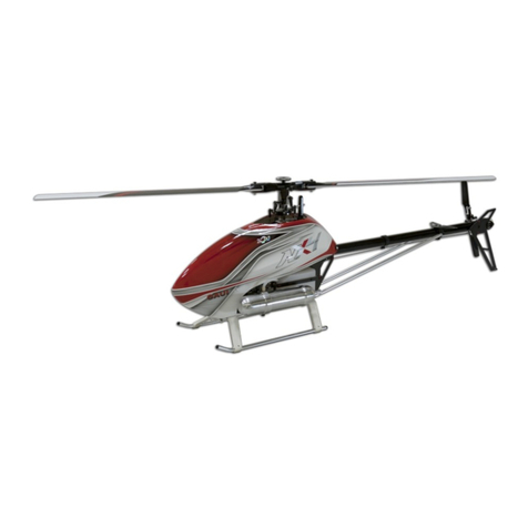
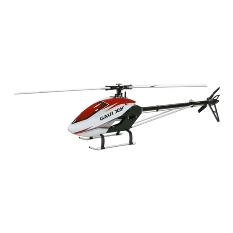
GAUI NX7 User manual

MADE IN TAIWAN
© 2014
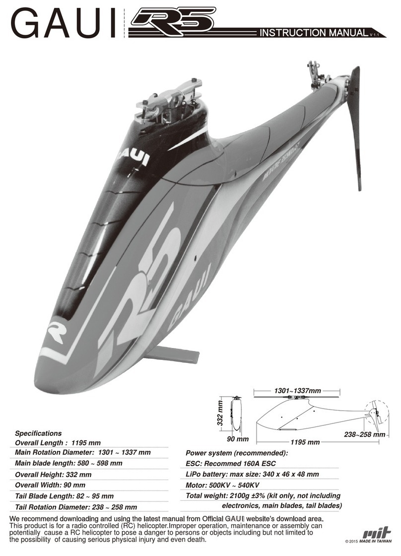
全長(キャノピー含む) : 1385 mm
1385 mm
スペック
ローター回転直径 : 1560~1620 mm
1560~1620 mm
メインブレード長 : 690~720 mm
690~720 mm
全高 : 415 mm
415 mm
200 mm
横幅 : 200 mm
テールブレード長 : 105mm
テールローター回転直径 : 290 mm
ドライブギアレシオ (16T): 8.18 : 1 : 4.71
飛行時間 : 7~8 分 (3D フライト)
燃料タンク : 660cc
総重量 : 4400g ±3%
V 2.0
290 mm
組み立て説明書

P.1 INDEX
We recommend downloading and using the latest manual from Official
GAUI website’s download area.
This product is for a radio controlled (RC) helicopter.
Improper operation, maintenance or assembly can potentially cause
a RC helicopter to pose a danger to persons or objects including but
not limited to the possibility of causing serious physical injury and
even death.
Tail case assembly 1~4 P.26
テールケースアッセンブリ 1~4
Swashplate assembly P.30
Main rotor grip assembly 1~3 P.31
CCPM servo assembly 1~5 P.34
Tail push rod / Throttle servo assembly P.36
Swashplate Guide / Muffler /Electronics / Canopy installation P.38
Spare parts list P.40
Frame assembly 1~8 P.4
Academy of Model Aeronautics (AMA) P.3
Preface / Liability Disclaimer P.2
Engine assembly 1~4 P.12
Frame assembly 9~12 P.16
Tail boom assembly 1~4 P.20
Main gear assembly 1~2 P.24
1.5~3mm Hexagon
screwdriver Needle-nosed pliers Diagonal cutting plier Ball Link Plier Scissors FBL system
Transmitter & Receiver
(6 channel +)
剪刀 陀螺儀
CCPM servo x3pcs Tail Specialized Servo x1pc Lubricant
one-way bearing grease
AB glue
潤滑油 / 單向軸承油AB黏著劑
#000000
5
#216000
M2x4 x3 pcs
4.0
lubricant Apply CA glue
Anaerobic adhesive.
AB glueGeneral thread lock. General thread lock.
Tighten screw and apply
thread lock.
Code Spare Part Number
Spare part number
Geometric dimensions
size specs.
Quantity
Assembly package
Throttle Specialized Servo x1pc
A B
Dial Pitch GaugeCA
始めに/免責事項
フレームアッセンブリ 1~8
フレームアッセンブリ 9~12
エンジンアッセンブリ 1~4
テールブームアッセンブリ 1~4
メインギアアッセンブリ 1~2
スワッシュプレートアッセンブリ
メインローターグリップアッセンブリ 1~3
CCPMサーボアッセンブリ 1~5
テールプッシュロッド/スロットルサーボアッセンブリ
スワッシュプレートガイド/マフラー
/エレクトロニクス/キャノピー インストレーション
スペアパーツリスト
1.5~3mm 六角ドライバー プライヤ— ボールリンクプライヤーニッパー
6ch以上の送受信機
瞬間接着剤
ラダーサーボx1個CCPMサーボx3個
ピッチゲージ
スロットルサーボx1個
ネジロック剤中強度 ABグル—
(エポキシ)
潤滑油 嫌気性接着剤の添付
ネジロック中強度を添付し
スクリューを締める
アッセンブリパッケージ コード スペアパーツナンバー
スペアパーツナンバー
数量
ジオメトリックディメンション
サイズスペック
目次 / 注意事項
最新版の説明書のダウンロードをお勧めします。GAUI JAPANサポートページをご確認ください。
この製品はラジオコントロールヘリコプターです。誤った製品の取り扱い、メンテナンス、組み立てを行うと
重大な事故につながります。更には他の人間や物を破壊、重大な事故、更には他人や自分死亡させる可
能性があります。存在する可能性は数多く考えられます。

Thank you for purchasing GAUI RC Helicopter from Tai Shih Hobby Corporation (TSH).
We hope you will enjoy the joy of flight.
In order to understand full assembly sequences, this instruction manual show the assembly
information of this model, even though some elements might be supplied as pre-assembled.
Please refer to manual whenever carrying out maintenance or replacing parts.
この度は GAUI RC ヘリコプター タイシホビーコーポレーション(TSH)をご購入いただきましてありがとうございます。組み立ての前にこの
説明書を熟読し十分特性を理解した上で組み立てを行ってください。幾つかの部品は既に仮組み立てが完了しております。メンテナンス、
リプレイス作業の為にもマニュアルによく目を通してください。
CAUTION: This radio controlled RC Helicopter is not a toy.
警告:このラジオコントロールヘリコプターはおもちゃではありません。
SAFETY PRECAUTIONS
This kit includes some pre-assembled components. Please check for any loose screws
and tighten them before you proceed with assembly.
You are responsible for assembly, safe operation, maintenance, inspection
and adjustment of the model.
Before beginning assembly, please read these instructions thoroughly.
Check all parts. If you find any defective or missing parts, contact your local dealer or
TSH distributor.
Before you proceed to RC Helicopter activity, please check and follow thoroughly related
regulation of aero modeling in your country/region.
安全上のご注意
このキットには幾つかの仮組み立てした製品が入っています。組み立ての前にネジの緩みを確認し締め付けを行ってください。
ユーザーは組み立て、安全なオペレーション、メンテナンスを、調整を行う責任があります。
組み立てを開始する前にこれらの指示を十分に理解してください。
不良または不足している部品がないか全ての部品を確認してください。もし、不良品、不足品があった場合はGAUI JAPANディーラー、購
入店へお問い合わせ下さい。組み立てを開始する前に、徹底的にこれらの指示をお読みください。
RCヘリコプターの飛行の前に必ず、法令や飛行場のルールを徹底的にチェックして下さい。
Disclaimer
This product is for a radio controlled (RC) Helicopter.
Improper operation, maintenance or assembly can potentially cause a RC Helicopter to
pose a danger to persons or objects including but not limited to the possibility of causing
serious physical injury and even death.
Moving components can present a hazard to operators, and anyone or anything that could
be in the flying area of the RC Helicopter.
Under no circumstance should a minor be allowed to operate this RC Helicopter without the
approval, monitor and direction of his parent or legal guardian who takes full responsibility for
all of the minor's actions.
This product is intended for being operated by experienced mature RC Helicopter
pilots under controlled safety conditions and on locations properly authorized and setup for safe
flying and away from other people.
Do not operate an RC Helicopter within the vicinity of residences, trees, electrical power lines
during inclement weather or near crowds of people.
The manufacturer and/or its distributors assume no responsibility or liability whatsoever for any
damages including but not limited to ones generated by incidental or consequential damages.
The operator of the RC Helicopter assumes all responsibility and liability that result from the
correct or incorrect operation of the RC Helicopter .
免責事項
この製品はラジオコントロールヘリコプターです。
誤った製品の取り扱い、メンテナンス、組み立てを行うと重大な事故につながります。更には他の人間や物を破壊、重大な事故、更には
死亡させる可能性があります。存在する可能性は数多く考えられます。
飛行場所においてはRCヘリコプターの飛行領域で行ってください。未成年者が飛行をする際は親権者の了解の元で飛行を行い、飛行時
には十分な監視を行ってください。この製品は、RCヘリコプターに熟練された方の使用を前提に設計されています。飛行の際は周囲の安
全を十分に確認し、公共のスペース、住宅、木、電線の近く、悪天候時は飛行をしないでください。
製造業者および/ディストリビューター/販売店はいずれについても一切の責任や、一切の義務を負いません。
RCヘリコプターの操縦者は全ての責任と義務を負う必要があります。正確な操縦、誤った操作など全てを含みます。
※次4ページ目はAMAレギュレーションとなっており、日本へは直接関係ありませんので割愛致します。
P.2
Preface / Liability Disclaimer 前置き / 免責事項
The Academy of Model Aeronautics (AMA) is a national organization representing
modelers in the United States.
Pleaserefer to theNationalModelAircraft safetycode fromAMAMember Manual for
details: http://www.modelaircraft.org/files/memanual.pdf
Partially reprinted rules that are especially pertinent for Radio Controlled flight:
RADIO CONTROL
1. All pilots shall avoid flying models over unprotected people.
2. I will complete a successful radio equipment ground-range check in accordance with the
manufacturer’s recommendations before the first flight of a new or repaired aircraft.
3.At all flying sites a safety line or linesmust be established,infront of which all
flying takes place.
Only personnel associated with flying themodel aircraftare allowedatorinfrontofthe
safetyline. Inthe case of air shows or demonstrations a straight safety line must be
established.
An area away from the safety line must be maintained for spectators. Intentional flying
behind the safety line is prohibited (see AMA Document #706 for Recommended Field
Layout).
4.Iwilloperatemymodelaircraftusingonlyradio-controlfrequencies currently allowed by the
Federal Communications Commission (FCC). Only individuals properly licensed by the
FCC are authorized to operate equipment on Amateur Band frequencies.
5.Iwillnotknowinglyoperatemymodelaircraftwithinthree(3)miles of any pre-existingflying
sitewithoutafrequency-managementagreement. (See AMA Document #922 for Testing for
RF Interference. See AMA Document#923 for Frequency Management Agreement.)
6.With the exception of events flown under official AMA Competition Regulations rules,
excluding takeoff and landing, no powered model may be flown outdoors closerthan 25 feet
toany individual,exceptfor the pilot and the Pilot’s helper(s) located at the flight line.
7.Under no circumstances may a pilot or other person touch a model aircraft in flight while
it is still under power, except to divert it from striking an individual. This does not apply to
model aircraft flown indoors.
8.Radio-controlled night flying requires a lighting system that provides the pilot with aclear
viewof themodel’sattitudeand orientationat all times.
9.The operator of a radio-controlled model aircraft shall control it duringthe entireflight,
maintainingvisualcontactwithoutenhancement other than by corrective lensesthatare
prescribedforthepilot.First-PersonView (FPV)flying mayonlybe conductedinaccordance
withthe proceduresoutlinedin AMA Document #550.
These special codes and appropriate documents may be obtained either from the
AMA Web site at www.modelaircraft.org or by contacting AMA.
Academy of Model Aeronautics 5161 East Memorial Drive Muncie, IN 47302
Tel.: (765) 287-1256
Fax: (765) 289-4248
P.3 Academy of Model Aeronautics (AMA)

P.4
Frame assembly フレームアッセンブリ
#073001
1#0Z1303
2
全てのネジ部分にネジロック剤を添付
All Screws on side plates should
be applied with thread locker.
1. Use CA glue to fix the on the frame.
1.CAグル—を使用し をフレームに接着します。
1
1
2
2
2

P.5 Frame assembly
1. Assemble Main Shaft Mount as figure shows.
2. Cut the rubber ring in half and use CA glue to stick the half ring on the
.
#0B1103
1
#073202
2
#073201
3
#073010
4
#073236
5
全てのネジ部分にネジロック剤を添付
ベアリング
12x24x6
M3x4
M3x6
M3x5
2
1
3
4
4
4
5
M3x4
#0R2304
x8 pcs M3x6
#0R3306
x2 pcs M3x5
#0R1305
x2 pcs
6
4
2 3 4
5
1.メインシャフトマウント組み立ては以下のイメージを参考に行います。
2.ラバーリングを半分にカットし瞬間接着剤で へ接着。
一直線
align
All Screws on side plates should
be applied with thread locker.
全てのネジ部分にネジロック剤を添付
フレームアッセンブリ

P.6
Frame assembly
2
M3x6
M3x6
M3x6
M3x6
M3x4
M3x4
M3x5
M3x12
M3x5
M3x5
M3x6
M3x5
3
7
8
1
12
ベアリング
10x19x5
ベアリング
5x13x4
4
6
5
6
ステップ2.
Step 2.
Step 3.
ステップ1.
Step 1.
ステップ4.
Step 4.
M3x4
#0R2304
x2 pcs M3x5
#0R2305
x4 pcs
456
M3x6
#0R2306
x8 pcs
M3x6
All Screws on side plates should
be applied with thread locker.
#0B1502
4#073237
8
#073001
3#073238
7
#0A8053
2
#073203
1
#0B1101
6
#073212
5
M3x6
#0R1306
x2 pcs M3x12
#0R4312
x1 pcs
2 3 5 6
1.サーボマウントは水平前後方向に移動できます。P.38のスワッシュ
プレートページを参考に調整
2. スターターシャフトベアリングマウントにベアリングを挿入
3. レインフォースフレームを組み立て。(図を参考に)
4. 嫌気性接着剤を使用しM3 x 12 ポストを固定
1. The metal servo mount can be moved horizontal direction and
please adjust the swashplate by following P.38.
2. Insert bearing to Starter Shaft Bearing Mount.
3. Assemble reinforcement frame as figure.
4. Use apply anaerobic adhesive to secure the M3 x 12 post.
adjustable for horizontal
direction.
前後方向に調整可能
フレームアッセンブリ
全てのネジ部分にネジロック剤を添付
ステップ3.

P.7 Frame assembly
全てのネジ部分にネジロック剤を添付
All Screws on side plates should
be applied with thread locker.
4
#073238
3#073223
6
#0B1401
2#073225
5
#073204
1#073237
4
12
26.4mm
M3
3
5
6
M3x5
M3x4
M3x4
M3x4
M3x4
M3x20
M3x20
M3x5
M3x5
M3x20
M3x12
M3x20
M3x4
#0R2304
x4 pcs #0R2305
4
Step 2.
5
M3x5
2
M3x12
#0R4312
x1 pcs
5 6
x3 pcs #0R2320
M3x20 x4 pcs
1. Use apply anaerobic adhesive to secure the M3 x 12 in the post.
2. Please tight up the M3x20 screws AFTER P.26 has been done.
1. 嫌気性接着剤を使用しM3 x 12 ポストを固定
2. M3 x 20はP.26が完了後に締め付けます。現時点では仮固定とします。
20
ベアリング
4x9x4
1
2
フレームアッセンブリ
ステップ2.

P.8
Frame assembly
All Screws on side plates should
be applied with thread locker.
#073010
1#073238
3
#073207
2
68
M3x5
#0R2305
x4 pcs M3x6
#0R3306
x3 pcs M3x8
#0R3308
x1 pcs
5
5 6
Tight M3x8 after P.26 has been done.
M3 x 8はP.26が完了後に締め付けます。現時点では仮固定とします。
M3x5
M3x5
M3x5
M3x5
M3x6 M3x8
1
26.4mm
M3
3
2
フレームアッセンブリ
全てのネジ部分にネジロック剤を添付

P.9 Frame assembly
フレームアッセンブリ
All Screws on side plates should
be applied with thread locker.
#0B1302
2#073219
4
#0A8621
1#0W3401
3
12
M3x10
#0R2310
x1 pcs M3x5
#0R2305
x10 pcs
5M3x12
#0R4312
x1 pcs
1 5 7
1. Assemble Push-rod adapt.
2. Install Push-rod adapt to the frame and note the direction of
Push-rod adapt.
3. Apply anaerobic adhesive to glue M3x12 into the post.
1. プッシュロッドアダプタ組み立て
2. プッシュロッドアダプタを図に示す方向になるようにフレームに取り付けます。
3. 嫌気性接着剤を添付しM3 x12をポストに入れます。
M3x5
M3x5
M3x12
M3x5
M3x5
M3x5
M3x5
M3x5
M3x5
M3x5
M3x5
10
1
Bearing
3x6x2.5 Washer
3.1x4.6x20.6
23
4
Balls
M2
M3x10
Step 3.
ステップ1.
Step 1. ステップ2.
Step 2.
ステップ3.
全てのネジ部分にネジロック剤を添付

P.10
Frame assembly
All Screws on side plates should
be applied with thread locker.
#073203
1
M3x4
#0R2304
x4 pcs M3x5
#0R2305
x5 pcs M3x6
#0R2306
x4 pcs
2 6
The metal servo mount can be moved horizontal direction and
please adjust the swashplate by following P.38.
adjustable for horizontal direction.
45
M3x5
M3x6
M3x5
M3x6
M3x5
M3x5 M3x4
M3x4
M3x5
M3x6
M3x6
M3x4
M3x4
6
1
Step 1.
全てのネジ部分にネジロック剤を添付
フレームアッセンブリ
メタルサーボマウントは前後方向に移動が可能です。
P.38を参考にスワッシュプレートに合わせてください。
ステップ1.
水平方向に調整

P.11
5
Frame assembly
All Screws on side plates should
be applied with thread locker.
Apply anaerobic adhesive to glue M3x12 in the post.
M3x5
#0R2305
x4 pcs M3x6
#0R1306
x2 pcs M3x12
#0R4312
x12 pcs
5
#073237
2
M3x12
M3x5
M3x5
M3x5
M3x6
M3x5
2
1
12
6
#0A8053
1
Step 1.
フレームアッセンブリ
ステップ1.
全てのネジ部分にネジロック剤を添付
嫌気性接着剤を添付しM3 x12をポストに入れます。

P.12
All Screws on side plates should
be applied with thread locker.
#073208
1
#073403
2
#073209
3
#073210
4
M3x6
#0R2306
x4 pcs M3x10
#0R1310
x2 pcs
M3x10
M4x20
4
3
610
8
M4x20 #0R1420 x4 pcs
9 10
20
1. Assemble fan and hub as right figure and install it to engine.
2. Please tight the crank nut first and then tight screw M3x10.
M3x6
1
2
Step 1.
Engine assembly エンジンアッセンブリ
ステップ1.
全てのネジ部分にネジロック剤を添付
1. ファンとハブを右の画像を参考に組み立てた後エンジンにインストールします。
2. 先にクランクナットを締めつけてからM3 x10のスクリューを締めこみます。

P.13
1. Install to and then tight after.
2. Secure to the hub by using screw M4x8.
8
M4x8
#0R2408
x2 pcs
11
#073216
3#073217
6
#073213
2#0B1502
5
#073211
1
Engine assembly
#077501
4
ベアリング
5x13x4
16T
M4x8
3
3
3
5
4
6
6
6
2
2
2
ワンウエイベアリング
12x18x16
Magnets
1
1
1
8.00
All Screws on side plates should
be applied with thread locker.
Step 1.
エンジンアッセンブリ
全てのネジ部分にネジロック剤を添付
ステップ1.
マグネット
1. 先に と を取り付けてから を締めます
2. M4 x 8を使用し をハブに取り付けます。

P.14
Engine assembly
All Screws on side plates should
be applied with thread locker.
M4x4
#0R4404
x2 pcs
12
M4x4
1
4
1. Install starter shaft head to starter shaft and secure it by using
two M4x4 screws.
2. Please check and test the smooth of operation of starter shaft after
complete the installment.
Please check after each flight.
If there is a shaking on, please re-install the
whole clutch and make sure all screws are tighten and glued.
Holding area
#073218
1
エンジンアッセンブリ
全てのネジ部分にネジロック剤を添付
固定エリア
1. スターターシャフトヘッドとスターターシャフトをM4 x4のスクリューを使用し締め付けます。
2. スターターシャフトのインストールが完了したらスムーズに動くか確認して下さい。
毎飛行後にこの部分を確認します。もし、グラグラしているようであれば全てのネジの締め込
みやネジロック剤の添付を行います。もしくは、もう一度取り付け作業をやり直してください。

P.15 Engine assembly
All Screws on side plates should
be applied with thread locker.
5
M3x5
#0R2305
x4 pcs M3x8
#0R1308
x2 pcs
10
M3x5
M3x8
M3x5
26.4mm
M3
2
1
1. Install fan set to engine and place the engine to the body.
2. Screw M3x5 and M3x8 to two side of frame.
3
8
5
#073408
1#0A8053
3
#073238
2
Step 2.
Step 3.Step 1.ステップ1.
ステップ2.
ステップ3.
全てのネジ部分にネジロック剤を添付
エンジンアッセンブリ
1. ファンセットをエンジンボディへ取り付けます。
2. M3 x 5 と M3 x 8 をフレーム両側に取り付けます。

P.16
3 5 14
Frame assembly
All Screws on side plates should
be applied with thread locker.
M3x35
M3x35
26.4mm
M3 1
26.4mm
3 1
3
2
5
4
#073008
2#0A8502
5
#073238
1#0A8053
4
#073402
3
M3x35 #0R7335 x4 pcs
1. Adjust proper angle of fuel tank to fit into the frame and secure it by two
M3x35 screws as the picture shows.
35.00
フレームアッセンブリ
全てのネジ部分にネジロック剤を添付
1. タンクをズラしたりしながらフレームにタンクを取り付け、M3 x 35のスクリューで固定します。
図を参考にします。

P.17 Frame assembly
All Screws on side plates should
be applied with thread locker.
26.4mm
M3
2
M3x14
M3x8
M3x5
M3x5
M3x14
M3x3
13
4
5
#0A8053
2#073221
5
#073205
1#074401
4
#073004
3
M3x14
#0R2314
x4 pcs M3x3
#0R4303
x4 pcs
5 6
M3x5
#0R2305
x3 pcs M3x8
#0R2308
x2 pcs
5
1. Assemble bottom frame and landing gear.
3
14.00
8.00
フレームアッセンブリ
全てのネジ部分にネジロック剤を添付
1. ボトムフレームとランディングギアを組み立て

P.18
Install to two side of frame.
Frame assembly
All Screws on side plates should
be applied with thread locker.
3
1
1
1
M3x6
M3x6
6
#073006
1
M3x6
#0R2306
x14 pcs
フレームアッセンブリ
全てのネジ部分にネジロック剤を添付
をフレーム両側に取り付け

P.19 Frame assembly
All Screws on side plates should
be applied with thread locker.
1
1
1
3x8
Canopy holder can be removed or keeped
#073404
1
Do not over tight the screws when install to prevent thread damage.
10
8
3x8
#0R7308
x14 pcs
フレームアッセンブリ
全てのネジ部分にネジロック剤を添付
を締め付ける際は締めすぎないように注意してください。樹脂パーツにはネジロック剤は使用しません。
キャノピーホルダーは取り除いてもそのままでも構いません
Table of contents
Other GAUI Toy manuals

GAUI
GAUI 330X Quad-Flyer User manual

GAUI
GAUI NEX6 User manual

GAUI
GAUI X5 User manual

GAUI
GAUI Hurricane 425 User manual

GAUI
GAUI X4 Combo User manual

GAUI
GAUI Hurricane 550 User manual

GAUI
GAUI X5 3D Flybarless User manual

GAUI
GAUI Hurricane 425 User manual

GAUI
GAUI NX4 User manual

GAUI
GAUI Hurricane 255 User manual
Popular Toy manuals by other brands

Amewi
Amewi AMX PLANES SWIFT 2100 Operation manual

Miniature Aircraft USA
Miniature Aircraft USA X-cell Whiplash 730E Assembly instructions

VQ Model
VQ Model TOMHAWK instruction manual

Traxxas
Traxxas 57046-4 owner's manual

Eduard
Eduard He 111P-2 interior S.A. quick start guide

Amewi
Amewi Conquer Race Truggy 1:16 manual