GBD F4 Guide

F4
IT UK FR ES NL
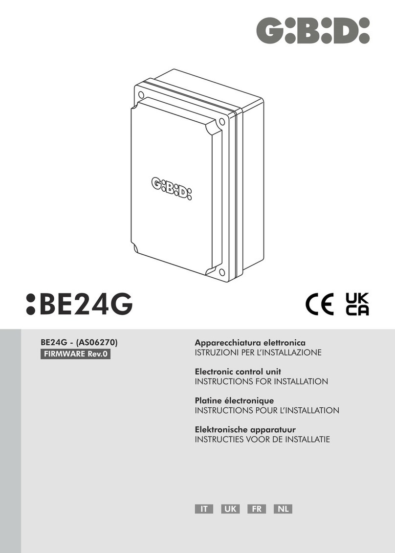
F4 (AS06320) Apparecchiatura elettronica
ISTRUZIONI PER L’INSTALLAZIONE
Electronic control unit
INSTRUCTIONS FOR INSTALLATION
Appareillage électronique
INSTRUCTIONS POUR L’INSTALLATION
Equipo electrónico
INSTRUCCIONES PARA LA INSTALACIÓN
Elektronische besturing
INSTRUCTIES VOOR DE INSTALLATIE

• Red warning LEDs for the N.C. contacts (FCAM1-FCCM1-FCAM2-FCCM2-PHOTO-STOP).
• Green warning LEDs for the N.O. contacts (START-PED).
• Control of one 12VAC electric lock.
• Management of the opening release stroke to release the electric lock and of the final stroke to hook the electric
lock. Enabling the opening release stroke, you also activate the final stroke in closing (1s of extra motion).
• Working time learning by procedure or set with trimmer.
• Slow-down in opening and closing, only by run time learning procedure.
• Pause and leaf-delay time adjustment.
• Fixed or intermittent flashing light control.
• Courtesy light control.
• Programming of automatic closing.
• Photocell active during closing (operation during opening can be selected with a DIP switch).
• Motor force adjustment with appropriate trimmer.
• Operating range: Automatic - Step-by-step with stop - Pedestrian.
• STOP input control functioning as STOP (lock) or edge (obstacle freeing).
• Hydraulic lock upkeep for hydraulic motors (DIP1_10 ON).
• DIP switch to disable the LIMIT SWITCH and PHOTOCELL inputs if not used.
2 - TECHNICAL SPECIFICATIONS/FUNCTIONS
1 - TECHNICAL SPECIFICATIONS
F4
230 VAC single-phase 50/60 Hz
1 or 2
230 VAC
230 VAC 40W max
24 VAC 3W max
Plug-in
-20°C +60°C
24 VAC 8W max
Control unit
Power supply
No. of motors
Motor power supply
Flashing light
Warning light
Radio receiver
Operating temperature
Accessory power supply
Type
AS06320
Code
12 VAC 15W max
Electric lock
IP55
Degree of protection
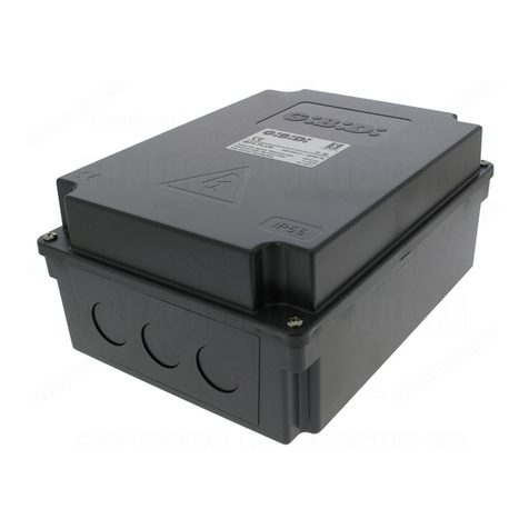
Electronic control unit for automation of
a swing gate, sliding gate, overhead door or barrier
with one or two 230 VAC motor
WARNINGS:
This product has been tested by GI.BI.DI. for full compliance with the requirements of the directives in force. GI.BI.DI. S.r.l. reserves
the right to change the technical data without prior notice in relation to product development.
CAREFULLY READ THESE INSTRUCTIONS BEFORE PROCEEDING WITH INSTALLATION.
Thank you for choosing GIBIDI.
DISPOSAL: GI.BI.DI. advises recycling the plastic components and to dispose of them at special authorised
centres for electronic components thus protecting the environment from polluting substances.
12
IT
F4 13
UK
F4
Dichiarazione di conformità CE
Il fabbricante:
GI.BI.DI. S.r.l.
Via Abetone Brennero, 177/B,
46025 Poggio Rusco (MN) ITALY
dichiara che il prodotto:
APPARECCHIATURA ELETTRONICA F4
è conforme alle seguenti Direttive:
e che sono state applicate le seguenti norme:
Il Rappresentante Legale
Michele Prandi
Data 05/07/2019
Inoltre dichiara che il prodotto non deve essere utilizzato finché la macchina in cui
sarà incorporato non sia stata dichiarata conforme alla Direttiva 2006/42/CE.
Ÿ2014/35/UE
Ÿ2014/30/UE
Ÿ2014/53/UE
Ÿ2011/65/UE
ŸIEC 61000-6-1:2016 RVL
ŸIEC 61000-6-2:2016 RVL
ŸIEC 61000-6-3:2020
ŸIEC 60335-2-103:2015+AMD1:2017+AMD2:2019 CSV

M1
Motor 1 connection (opening)
1
Motor 1 connection (common)
2
5 - ELECTRICAL CONNECTIONS: TERMINAL BOARDS
3
5
4
6
7
Motor 1 connection (closing)
Motor 2 connection (opening)
Motor 2 connection (common)
Motor 2 connection (closing)
8
COURTESY LIGHT output (LIVE) if DIP1_9 = OFF
Fixed output for FLASHING LIGHT if DIP1_9 = ON
COURTESY LIGHT output (NEUTRAL) if DIP1_9 = OFF
Fixed output for FLASHING LIGHT if DIP1_9 = ON
Description
Terminal Position Signal
230VAC power supply NEUTRAL
9
230VAC power supply LIVE
10
11
12
Earth wire connection
Earth wire connection
M2
N
L
EARTH
EARTH
COMMON for LIMIT SWITCH, PHOTOCELL, STOP, START and PEDESTRIAN inputs
13
Closing limit switch input - MOTOR 2 (N.C.)
14
15
16
Opening limit switch input - MOTOR 2 (N.C.)
Closing limit switch input - MOTOR 1 (N.C.)
M3
COM
FCCM2
FCAM2
FCCM1
Opening limit switch input - MOTOR 1 (N.C.)
17
PHOTOCELL input (N.C.)
18
19
20
START input (N.O.)
24VAC output for PHOTOCELL, ACCESSORIES power supply (max 8W)
FCAM1
PHOTO
START
24Vac
0VAC output for PHOTOCELL, ACCESSORIES and ELECTRIC LOCK power supply
21
12VAC output for ELECTRIC LOCK (max 15W)
22
23
24
0Vac
EL1
STOP
PED
COMMON for LIMIT SWITCH, PHOTOCELL, STOP, START and PEDESTRIAN inputs
25
26
27
ANTENNA BRAID input
ANTENNA CORE input
COM
COM
STOP input if DIP2_1 in OFF - EDGE input if DIP2_1 in ON.
If not used, make a bridge with terminal 25 and open jumper SW15.
PEDESTRIAN start input (N.O.) - ACTS ON MOTOR 1.
The pedestrian operation is made using automatic logic and cannot be modified.
28
M4
29
RELAY CLEAN-CONTACT FOR:
• Fixed-light flashing light connection taking the power supply from terminals 7 and 8
(the relay flashes fast during closing and slow during opening).
• Controlling a warning light to signal gate movement. Connect a 24VAC light powered
by terminals 20-21 (max 3W). The light flashes fast during closing, slow during
opening, it is on during pause and it is off during sleep time.
3 - INSTALLATION WARNINGS
• Before proceeding with installation, fit a differential magnetothermal switch with a maximum capacity of 10A
upstream of the system. The switch must guarantee omnipolar separation of the contacts with an opening
distance of at least 3mm.
• To prevent possible interference, differentiate and always keep the power cables (minimum cross-section
1.5 mm²) separate from the signal cables (minimum cross-section 0.5 mm²).
• Make the connections referring to the following tables and the labeling on the control board. Be extremely
careful to connect in series all the devices that are connected to the same N.C. (normally closed) input, and in
parallel all the devices that share the same N.O. (normally open) input.
• Incorrect installation or improper use of the product may compromise system safety.
• Keep all the materials contained in the packaging away from children since they pose a potential hazard.
• The manufacturer declines all responsibility for improper functioning of the automated device if the original
components and accessories suitable for the specific application are not used.
• When installation is complete, always carefully check proper functioning of the system and the devices used.
• This instruction manual addresses professionals qualified to install “live equipment” and therefore requires good
technical knowledge and installation in compliance with the regulations in force.
• Maintenance must be carried out by a competent person.
• Before carrying out any cleaning or maintenance operation, disconnect the control unit from the mains.
• The control unit described in this document may only be used for the purpose for which it was designed.
• Check the intended end use and take all the necessary safety precautions.
• Use of the products for purposes different from the intended use has not been tested by the manufacturer and
is therefore on full responsibility of the installer.
• Mark the automated device with visible warning plates.
• Warn the user that children or animals should not play or stand near the gate.
• Appropriately protect the dangerous points (for example, using a sensitive edge).
• Do not install in an explosive enviroment.
4 - WARNINGS FOR THE USER
In the event of an operating fault or failure, isolate the power upstream of the control unit and call Technical
Service. Periodically check functioning of the safety devices. Any repairs must be carried out by specialised
personnel using original and certified materials.
The product may not be used by children or persons with reduced physical, sensorial or mental capacities, or
lacking experience and knowledge, unless appropriately instructed. Do not access the circuit board for
adjustments and/or maintenance.
WARNING: IMPORTANT SAFETY INSTRUCTIONS.
It is important for the safety of persons to follow these instructions.
Keep this instruction manual.
14
UK
F4 15
UK
F4

8 - DIP SWITCH DIP1
The settings are stored during the rest phase (gate closed
The default settings are highlighted in the boxes with grey background.
).
DIP1_1
ON
PHOTOCELL
DURING
OPENING
OFF
Description
DIP Status
Function
When the photocell is broken/interrupted during both opening and closing, the gate
motion is ceased until the photocell is re-made.
Subsequently the gate will always OPEN.
Breaking or interrupting the photocell during PAUSE will cause the pause-time
to begin counting down again.
The photocell stops and immediately inverts the gate motion during closing
while it is uninfluential during opening.
Breaking or interrupting the photocell during PAUSE will cause the pause-time
to begin counting down again.
DIP 31_ ELECTRIC LOCK
RELEASE STROKE
ON
Operation: following a START, OPENING or PEDESTRIAN command, the
following will occur in sequence:
• electric lock activation
• closing pulse of 1 second
• opening
• after 2 seconds, electric lock deactivation
Operation AT THE END OF CLOSING CYCLE (ONLY WITH SLOW-DOWN
ENABLED):
• extra movement in closing of 1 second with FORCE trimmer settings.
This function cannot be activated with a sliding gate configuration and is
unadvisable with electromechanical operators.
Electric lock release stroke disabled.
Simultaneous electric lock activation and opening.
OFF
ON
OPERATING
LOGIC
DIP 21_
AUTOMATIC logic
Operation in response to the START command:
STEP-BY-STEP WITH STOP logic
Operation in response to the START command:
• Gate closed
• Gate closed
• During opening
• During opening
• During closing
• During closing
• After a STOP
• Gate open
• Gate open (PAUSE)
OFF
(SEE PAUSE TRIMMER)
6.3A T
Protects the circuit board and the accessories.
160mA T
F1
F2
6 - PROTECTION FUSES
Protects the circuit board and the motors.
7 - WARNING LEDs
Description
TypeValuePosition
RED
RED
RED
RED
RED
GREEN
GREEN
BLUE
FCCM2
FCAM2
FCCM1
FCAM1
PHOTO
START
PED
MEMO
L1
L2
L3
L4
L5
L6
L8
L9
Description
SignalColourLED
Always on. Turns off when the CLOSING LIMIT SWITCH of motor 2 is reached.
Always on. Turns off when the OPENING LIMIT SWITCH of motor 2 is reached.
Always on. Turns off when the CLOSING LIMIT SWITCH of motor 1 is reached.
Always on. Turns off when the OPENING LIMIT SWITCH of motor 1 is reached.
Always on. Turns off when the photocell is broken/interrupted.
Comes on when the START command is activated and goes off when released.
Comes on when the PED. start command is activated and goes off when released.
RED
SAF. / STOP
L10
The control unit is blocked waiting to do the learning cycle.
It is necessary to do the learning cycle.
The control unit is in pre-learning phase after the activation of memo
button.
At rest and during the learning, the control unit is set for the operation
with 1 motor.
At rest and during the learning, the control unit is set for the operation
with 2 motors.
Learning correctly made.
Signalling made also on WARNING and FLASHING LIGHT.
Learning aborted. Check photo-stop-edge-ped inputs.
Signalling made also on WARNING and FLASHING LIGHT.
30s ON
0.3s ON - 0.3s OFF
0.3s ON - 0.3s OFF
0.3s ON - 1s OFF
X4
0.6s ON 0.6s OFF
CONTINUOUS
3s ON-1s OFF
X3
0.2s ON-2s OFF
CONTINUOUS
0.2s ON - 0.2s OFF
CONTINUOUS
0.2s ON - 1s OFF
Always on. It turns off after STOP/EDGE INPUT intervention.
16
UK
F4 17
UK
F4
If automatic closing is enabled then the gate stops
OPENS
STOPS
STOPS
Inverts the motion
If automatic closing is enabled (see PAUSE trimmer
function) then the pause-time begins again, otherwise it
closes. If automatic closing is enabled (as above) then a
permanent START command (always closed) will hold
the gate open, otherwise it closes.
OPENS
OPENS
UNINFLUENTIAL

10 - JUMPER SW15
Description
JUMPER Status
Function
SW15 TERMINAL 23
FUNCTIONING
N.C. devices are connected to STOP/EDGE input (23)
Resistive 8,2KOhm devices are connected to STOP/EDGE input (23)
The settings are stored during the rest phase (gate closed).
The default settings are highlighted in the boxes with grey background.
11 - TRIMMER ADJUSTMENT
Before powering the control unit, proceed with the following checks:
• Check the electrical connections; improper connection may be harmful to both the control unit and the operator.
• Check that the limit switches (if used) are in the correct position.
• Always provide for mechanical stops during opening and closing
• Set the DIP switches and trimmers for the desired operation.
12 - PRELIMINARY CHECKS
Description
Trimmer Default
FORCE
PAUSE
RUN
TIME
Turning clockwise adjusts (increases) the motor torque from 25% to 100%.
The first 3 seconds of movement take place with 100% of motor torque (force).
Turning clockwise adjusts (increases) the pause time from 3 to 103 seconds.
Automatic closing is disabled if adjusted to minimum. See operating logic DIP1_2.
Turning clockwise adjusts (increases) the closing delay time of leaf 1 with respect to leaf 2
from 0 to 20 seconds. The leaf-delay during opening is fixed at 2 seconds.
Set to minimum, the delays during both opening and closing will be cancelled
(version with 2 sliding gates), disables the opening release stroke DIP1_3 and the maintenance
of the hydraulic lock upkeep.
Set to the minimum (fully counter-clockwise), it will permit the RUN TIME LEARNING
PROCEEDURE with SLOW-DOWN to take place.
Turning clockwise, it adjusts the working time from 3.5 to 136 sec. and excludes learning
procedure and slow down.
P.S.
TIME
(LEAF-DELAY TIME)
The settings are stored during the rest phase (gate closed
The default settings are highlighted in the boxes with grey background.
).
DIP1_4
DIP1_5
DIP1_6
DIP1_7
DIP1_8
DIP1_9
DIP1_10
MOTOR 1 OPENING
LIMIT SWITCH
MOTOR 1 CLOSING
LIMIT SWITCH
MOTOR 2 OPENING
LIMIT SWITCH
MOTOR 2 CLOSING
LIMIT SWITCH
PHOTOCELL
TERMINALS 7-8
FUNCTIONING
HYDRAULIC LOCK
UPKEEP
ON
OFF
ON
DIP2_1
DIP2_2
ON
TERMINAL 23
FUNCTIONING
TERMINAL M4
FUNCTIONING
OFF
Description
DIP Status
Function
The STOP input (23) functions as EDGE and when activated, will invert the
motion for 2 seconds in order to free the obstacle.
See also jumper SW15.
The STOP input (23) functions as STOP and when activated, will stop the
motion. See also jumper SW15.
The outputs 7-8 of the terminal board are used to control a FLASHING LIGHT
equipped with its own flashing circuit.
The outputs 7-8 of the terminal board are used to control a COURTESY LIGHT
that remains active for 2 minutes after the motor movement.
For HYDRAULIC motors only.
If the gate has not performed any operation in the last 5 hours, a 2-second
closing pulse is given.
THE STOP KEY DISABLES THE FUNCTION.
Disables the limit switch input
Enables the limit switch input
Disables the limit switch input
Enables the limit switch input
Disables the limit switch input
Enables the limit switch input
Disables the limit switch input
Enables the limit switch input
Disables the photocell input
HYDRAULIC LOCK UPKEEP deactivated.
Terminal M4 operates as WARNING LIGHT.
Terminal M4 operates as FLASHING LIGHT.
In this mode, the terminals 28-29 can be used to connect a FLASHING LIGHT
without a flashing circuit.
Keep this OFF, do not change.
Enables the photocell input
ON
ON
ON
ON
ON
OFF
ON
OFF
OFF
OFF
OFF
OFF
OFF
In the case of a system with only one
motor and using the limit switches,
the DIP switches 4, 5, 6 and 7 are
to be set to OFF; while if using only
one type of limit switch (e.g. FCAM1
and/or FCCM1), enable only the
corresponding DIP switch (set to OFF).
9 - DIP SWITCH DIP2
DIP2_3
DIP2_4
Extended positional time recovery:
- Ideal for AGO motors with run time learning done
- Ideal for TOP EVO motors with hydraulic slowdown
Normal positional time recovery.
ON
OFF
POSITIONAL TIME
RECOVERY
OFF
UNUSED
18
UK
F4 19
UK
F4

Movements made during the learning with 2 motors:
ŸMotor 2 closes until running into the limit switch or until receiving a START impulse.
ŸMotor 1 closes until running into the limit switch or until receiving a START impulse.
ŸPause of 1 second.
ŸMotor 1 opens until running into the limit switch or until receiving a START impulse.
ŸMotor 2 opens until running into the limit switch or until receiving a START impulse.
ŸPause of 1 second.
ŸMotor 2 closes until running into the limit switch or until receiving a START impulse.
ŸMotor 1 closes until running into the limit switch or until receiving a START impulse.
ŸPause of 1 second.
ŸMotor 1 opens, the first START command causes the beginning of the decelerated motion, the following
START command or the opening limit switch causes the end of motor 1 motion in opening.
ŸMotor 2 opens, the first START command causes the beginning of the decelerated motion, the following
START command or the opening limit switch causes the end of motor 2 motion in opening.
ŸPause of 1 second.
ŸMotor 2 closes, the first START command causes the beginning of the decelerated motion, the following
START command or the closing limit switch causes the end of motor 2 motion in closing.
ŸPause of 1 second.
ŸMotor 2 closes, the first START command causes the beginning of the decelerated motion, the following
START command or the closing limit switch causes the end of motor 2 motion in closing.
ŸEnd of learning, the LED L9 and the flashing light signal that the learning has been completed and turn off.
Movements made during the learning with 1 motor:
ŸMotor 1 closes until running into the limit switch or until receiving a START impulse.
ŸPause of 1 second.
ŸMotor 1 opens until running into the limit switch or until receiving a START impulse.
ŸMotor 1 closes until running into the limit switch or until receiving a START impulse.
ŸMotor 1 opens, the first START command causes the beginning of the decelerated motion, the following
START command or the opening limit switch causes the end of the motion of motor 1 in opening.
ŸPause of 1 second.
ŸMotor 1 closes, the first START command causes the beginning of the decelerated motion, the following
START command or the closing limit switch causes the end of the motion of motor 1 in closing.
ŸEnd of learning, the LED L9 and the flashing light signal that the learning has been completed and turn off.
In the event of the learning procedure not work then check the signaling of LED L9.
• Power the device.
• Check that the red LEDs of the N.C. contacts are on and the green LEDs of the N.O. contacts are off.
• Check by tripping the limit switches (if used and enabled with the appropriate DIP switches) that the corresponding
LEDs go off.
• Check by passing through the photocell beam (if used and enabled with the appropriate DIP switch) that the
corresponding LED goes off.
• Remove any obstacle from the gate’s range.
• Check that the motors are locked and ready for the operation in the HALF-OPEN position.
Only in case of operation without learning and with RUN TIME trimmer not to the minimum:
• At the first command, the control unit starts an opening movement: check that the direction of gate motion
is correct. On the contrary, remove the power supply from the control unit, invert the wires of terminal M1 (position
1-3 for motor 1) (4-6 for motor 2). Supply power again and give START command.
• During the operation of the gates, turn the FORCE trimmer anti-clockwise until the desired force/speed is obtained.
13 - RUN TIME LEARNING PROCEDURE
ŸThe «RUN TIME» trimmer must be at the minimum to be able to do the learning procedure. With any adjusting
different from the minimum, the working time, both in opening and closing, is determined by the «RUN TIME»
trimmer and the slow-down will be disabled.
ŸThe breaking or interrupting of any device (PED, PHOTO, STOP/SAFETY) during the learning phase causes
the interruption and the exit from the learning cycle and it is necessary to repeat it.
ŸDuring the learning cycle, the WARNING LIGHT is off and it will be briefly on after receiving a START
command.
ŸThe operators motion, during the learning procedure, occurs with the force set on FORCE trimmer.
ŸSliding gate operators MUST have opening and closing limit switches. All the other types of motor
must have the limit switches or the mechanical stops on the ground.
ŸSliding gate operators must have the <<LEAF DELAY TIME>> trimmer set to the minimum.
ŸThe run time learning is not compatible with TOP EVO operators with hydraulic slowdown.
Learning procedure:
ŸUnlock the operators and set the gates HALF-WAY.
ŸLock-off the operators.
ŸCheck that there are the mechanical stops on the ground and/or on the operator in opening and closing.
ŸRemove any obstacle from the the swing area of the gates.
ŸCheck that LED L1, L2, L3, L4, L5 and L10 are on.
ŸCheck that «RUN TIME» trimmer is at the minimum.
ŸPress MEMO button for 2 seconds.
ŸLED L9 is on and remains on for 30 seconds, after which it will switch off as the control unit automatically exits
from the learning procedure.
ŸChoose within 30 seconds (LED L9 on) using the MEMO button the number of motors you have to use.
The first press of the button enables the operation with 1 motor and LED L9 blinks, the second press of
MEMO button enables the operation with 2 motors and LED L9 blinks twice.
ŸThe sequence repeats itself any time you push MEMO button.
ŸPush the button 1 (START) of the transmitter or give a START impulse from the terminal board.
Check that the movement of the motors is in the right direction (in closing at the beginning). On the contrary,
block the learning cycle with any safety device, remove the power supply from the control unit, invert the wires
of terminal M1 (position 1-3 for motor 1) (4-6 for motor 2) and repeat the procedure.
20
UK
F4 21
UK
F4

Movements made during the learning with 2 motors:
ŸMotor 2 closes until running into the limit switch or until receiving a START impulse.
ŸMotor 1 closes until running into the limit switch or until receiving a START impulse.
ŸPause of 1 second.
ŸMotor 1 opens until running into the limit switch or until receiving a START impulse.
ŸMotor 2 opens until running into the limit switch or until receiving a START impulse.
ŸPause of 1 second.
ŸMotor 2 closes until running into the limit switch or until receiving a START impulse.
ŸMotor 1 closes until running into the limit switch or until receiving a START impulse.
ŸPause of 1 second.
ŸMotor 1 opens, the first START command causes the beginning of the decelerated motion, the following
START command or the opening limit switch causes the end of motor 1 motion in opening.
ŸMotor 2 opens, the first START command causes the beginning of the decelerated motion, the following
START command or the opening limit switch causes the end of motor 2 motion in opening.
ŸPause of 1 second.
ŸMotor 2 closes, the first START command causes the beginning of the decelerated motion, the following
START command or the closing limit switch causes the end of motor 2 motion in closing.
ŸPause of 1 second.
ŸMotor 2 closes, the first START command causes the beginning of the decelerated motion, the following
START command or the closing limit switch causes the end of motor 2 motion in closing.
ŸEnd of learning, the LED L9 and the flashing light signal that the learning has been completed and turn off.
Movements made during the learning with 1 motor:
ŸMotor 1 closes until running into the limit switch or until receiving a START impulse.
ŸPause of 1 second.
ŸMotor 1 opens until running into the limit switch or until receiving a START impulse.
ŸMotor 1 closes until running into the limit switch or until receiving a START impulse.
ŸMotor 1 opens, the first START command causes the beginning of the decelerated motion, the following
START command or the opening limit switch causes the end of the motion of motor 1 in opening.
ŸPause of 1 second.
ŸMotor 1 closes, the first START command causes the beginning of the decelerated motion, the following
START command or the closing limit switch causes the end of the motion of motor 1 in closing.
ŸEnd of learning, the LED L9 and the flashing light signal that the learning has been completed and turn off.
In the event of the learning procedure not work then check the signaling of LED L9.
• Power the device.
• Check that the red LEDs of the N.C. contacts are on and the green LEDs of the N.O. contacts are off.
• Check by tripping the limit switches (if used and enabled with the appropriate DIP switches) that the corresponding
LEDs go off.
• Check by passing through the photocell beam (if used and enabled with the appropriate DIP switch) that the
corresponding LED goes off.
• Remove any obstacle from the gate’s range.
• Check that the motors are locked and ready for the operation in the HALF-OPEN position.
Only in case of operation without learning and with RUN TIME trimmer not to the minimum:
• At the first command, the control unit starts an opening movement: check that the direction of gate motion
is correct. On the contrary, remove the power supply from the control unit, invert the wires of terminal M1 (position
1-3 for motor 1) (4-6 for motor 2). Supply power again and give START command.
• During the operation of the gates, turn the FORCE trimmer anti-clockwise until the desired force/speed is obtained.
13 - RUN TIME LEARNING PROCEDURE
ŸThe «RUN TIME» trimmer must be at the minimum to be able to do the learning procedure. With any adjusting
different from the minimum, the working time, both in opening and closing, is determined by the «RUN TIME»
trimmer and the slow-down will be disabled.
ŸThe breaking or interrupting of any device (PED, PHOTO, STOP/SAFETY) during the learning phase causes
the interruption and the exit from the learning cycle and it is necessary to repeat it.
ŸDuring the learning cycle, the WARNING LIGHT is off and it will be briefly on after receiving a START
command.
ŸThe operators motion, during the learning procedure, occurs with the force set on FORCE trimmer.
ŸSliding gate operators MUST have opening and closing limit switches. All the other types of motor
must have the limit switches or the mechanical stops on the ground.
ŸSliding gate operators must have the <<LEAF DELAY TIME>> trimmer set to the minimum.
ŸThe run time learning is not compatible with TOP EVO operators with hydraulic slowdown.
Learning procedure:
ŸUnlock the operators and set the gates HALF-WAY.
ŸLock-off the operators.
ŸCheck that there are the mechanical stops on the ground and/or on the operator in opening and closing.
ŸRemove any obstacle from the the swing area of the gates.
ŸCheck that LED L1, L2, L3, L4, L5 and L10 are on.
ŸCheck that «RUN TIME» trimmer is at the minimum.
ŸPress MEMO button for 2 seconds.
ŸLED L9 is on and remains on for 30 seconds, after which it will switch off as the control unit automatically exits
from the learning procedure.
ŸChoose within 30 seconds (LED L9 on) using the MEMO button the number of motors you have to use.
The first press of the button enables the operation with 1 motor and LED L9 blinks, the second press of
MEMO button enables the operation with 2 motors and LED L9 blinks twice.
ŸThe sequence repeats itself any time you push MEMO button.
ŸPush the button 1 (START) of the transmitter or give a START impulse from the terminal board.
Check that the movement of the motors is in the right direction (in closing at the beginning). On the contrary,
block the learning cycle with any safety device, remove the power supply from the control unit, invert the wires
of terminal M1 (position 1-3 for motor 1) (4-6 for motor 2) and repeat the procedure.
20
UK
F4 21
UK
F4

Effect
Gate/door locked
Device
Edge detection before motion
Signalling
3 slow flashes
16 - SUMMARY OF FLASHING LIGHT SIGNALLING
Photocell break/interruption at rest in presence of
a START command ( DIP1_1 = ON ) 5 fast flashes When released, it opens
Opening
Closing
0,8s ON, 0,8s OFF
0,4s ON, 0,4s OFF
The gate is opening
The gate is closing
LEARNING OK Learning correctly made
LEARNING FAILED Learning failed
3s ON, 1s OFF
Repeated 3 times
0,3s ON, 0,3s OFF
Repeated 4 times
14 - SOFT START
This function adds 1s at reduced speed at the beginning of each movement. It is particularly recommended for
the electromechanical operators.
ŸWrite down DIP1_1 position.
ŸCut power to the control unit.
ŸPress and hold MEMO button.
ŸSupply the control unit.
ŸRelease MEMO button.
ŸThe blue led L9 starts to flash at regular intervals:
- short flashings, inactive function
- longer flashings, active function.
Ÿ· The flashing light will light up steadily
ŸBring DIP1_1 in ON to activate the function or in OFF to deactivate it.
ŸPress and hold MEMO button.
ŸAfter a few seconds, the led L9 will turn off and the flashing light will make two short flashings to confirm the
correct storage.
ŸBring DIP1_1 back to its original position.
• Make some opening and closing cycles to check the right operation of the automation and adjust the doors
force, acting on FORCE trimmer. If you have to make large adjustments from the values used during the learning
sequence then it may be necessary to repeat the learning procedure.
• Check the right operation of the automation.
14 - FINAL CHECKS
22
UK
F4 23
UK
F4
Date 05/07/2019
UKCA Declaration of conformity
The manufacturer:
GI.BI.DI. S.r.l.
Via Abetone Brennero, 177/B,
46025 Poggio Rusco (MN) ITALY
Declares that the product:
ELECTRONIC CONTROL UNITF4
Are in conformity with the essential requirements and other relevant requirement of:
and that the following harmonised standards have been applied:
The legal Representative
Michele Prandi
Restriction of the Use of Certain Hazardous Substances
in Electrical and Electronic Equipment Regulations 2012;
Electrical Equipment (Safety) Regulations 2016;
Radio Equipment Regulations 2017;
ŸEN 61000-6-1
ŸEN 61000-6-2
CE Declaration of conformity
The manufactuerer:
GI.BI.DI. S.r.l.
Via Abetone Brennero, 177/B,
46025 Poggio Rusco (MN) ITALY
Declares that the product:
ELECTRONIC CONTROL UNIT F4
are in conformity with the following directives:
and that the following harmonized standards have been applied:
Il Rappresentante Legale
Michele Prandi
Data 05/07/2019
Ÿ2014/35/UE
Ÿ2014/30/UE
ŸIEC 61000-6-1:2016 RVL
ŸIEC 61000-6-2:2016 RVL
ŸEN 61000-6-3
ŸEN 60335-1
Ÿ2014/53/UE
Ÿ2011/65/UE
ŸIEC 61000-6-3:2020
ŸIEC 60335-2-103:2015+AMD1:2017+AMD2:2019 CSV

NOTE / NOTESNOTE / NOTES
58 F4 59
F4
IT-UK

NOTE / NOTESNOTE / NOTES
58 F4 59
F4
IT-UK

GI.BI.DI. S.r.l.
Via Abetone Brennero, 177/B
46025 Poggio Rusco (MN) - ITALY
Tel. +39.0386.52.20.11
Fax +39.0386.52.20.31
E-mail: [email protected]
Numero Verde: 800.290156
w w w . g i b i d i . c o m
Cod. AIC6580 - 02/2022 - Rev. 01
This manual suits for next models
1
Table of contents
Other GBD Control Unit manuals
Popular Control Unit manuals by other brands
CMR Electrical
CMR Electrical DPC200 manual

Siko
Siko AS510/1 User information

Vag
Vag GA INDUSTRIES 983-D Installation, operation and maintenance manual
HEIDENHAIN
HEIDENHAIN UM 112D Replacing Instructions

Polycom
Polycom SpectraLink 6000 System Facility Preparation
A.R.I.
A.R.I. D-020 Installation operation & maintenance
Siemens
Siemens SINUMERIK 840D Description of Functions
DAV TECH
DAV TECH DA 400 EV Installation and maintenance guide

Regin
Regin PCMTV DN50-250 Instruction
BLB hydraulic
BLB hydraulic BM70 instruction manual
Honeywell
Honeywell SUPER TRADELINE VR8300A installation instructions

Telit Wireless Solutions
Telit Wireless Solutions GE310-GNSS Hardware Design Guide
