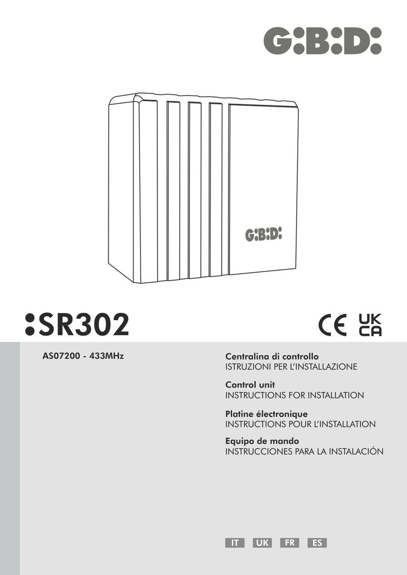
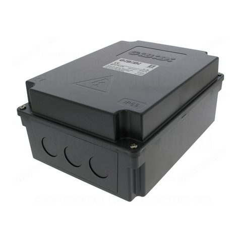
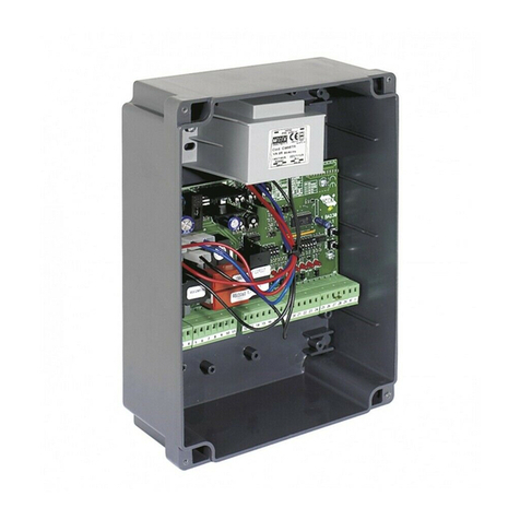
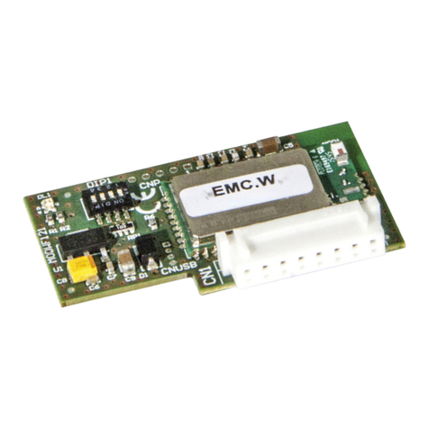
GBD SR302 Guide

IT UK
Centralina di controllo
ISTRUZIONI PER L’INSTALLAZIONE
Control unit
INSTRUCTIONS FOR INSTALLATION
SR302
AS07300 - 868MHz
Platine électronique
INSTRUCTIONS POUR L’INSTALLATION
Equipo de mando
INSTRUCCIONES PARA LA INSTALACIÓN
FR ES

• This product has been tested in Gi.Bi.Di. verifying the perfect correspondence of the characteristics to the
current directive.
• Gi.Bi.Di. S.r.l. reserves the right to modify the technical data without prior notice depending on the product
development.
UK
PLEASE READ CAREFULLY THIS MANUAL BEFORE PROCEEDING WITH THE INSTALLATION.
• Questo prodotto è stato collaudato in GI.BI.DI. verificando la perfetta corrispondenza delle caratteristiche
alle direttive vigenti.
• GI.BI.DI. S.r.l. si riserva la facoltà di modificare i dati tecnici senza avviso, in funzione dell'evoluzione del
prodotto.
IT
LEGGERE ATTENTAMENTE QUESTO MANUALE PRIMA DI PROCEDERE ALL’INSTALLAZIONE.
• Ce produit a été testé en GI.BI.DI., en vérifiant la parfaite correspondance des caractéristiques aux
directives en vigueur.
• GI.BI.DI. S.r.l. se réserve la faculté de modifier les données techniques sans préavis, en fonction de
l'évolution du produit.
LIRE CETTE NOTICE AVEC ATTENTION AVANT DE PROCÉDER À L'INSTALLATION.
FR
• Este producto ha sido probado en GI.BI.DI. averiguando la perfecta correspondencia de las
características a las normas vigentes.
• GI.BI.DI. S.r.l. se reserva el derecho de modificar los datos técnicos sin aviso, en función de la evolución
del producto.
LEER CON ATENCIÓN ESTE MANUAL ANTES DE PROCEDER CON LA INSTALACIÓN.
ES
SCHEMA ELETTRICO / ELECTRICAL CONNECTIONS / SCHÉMA ÉLECTRIQUE / ESQUEMA ELÉCTRICO
SCHEMA FISSAGGIO APPARECCHIATURA / CONTROL UNIT FIXING SCHEME /
SCHÉMA FIXATION PLATINE ÉLECTRONIQUE / ESQUEMA FIJACIÓN EQUIPO DE MANDO
ON
SW1
DL1
DL2
DL3
DL4
DL5
DL6
DL7
DL8
DL10
DL9
A1
1 2 3 4 5 6 7 8 9 10 11 1213 14
SR302 3
SR302
2
IT UK FR ES

• This product has been tested in Gi.Bi.Di. verifying the perfect correspondence of the characteristics to the
current directive.
• Gi.Bi.Di. S.r.l. reserves the right to modify the technical data without prior notice depending on the product
development.
UK
PLEASE READ CAREFULLY THIS MANUAL BEFORE PROCEEDING WITH THE INSTALLATION.
• Questo prodotto è stato collaudato in GI.BI.DI. verificando la perfetta corrispondenza delle caratteristiche
alle direttive vigenti.
• GI.BI.DI. S.r.l. si riserva la facoltà di modificare i dati tecnici senza avviso, in funzione dell'evoluzione del
prodotto.
IT
LEGGERE ATTENTAMENTE QUESTO MANUALE PRIMA DI PROCEDERE ALL’INSTALLAZIONE.
• Ce produit a été testé en GI.BI.DI., en vérifiant la parfaite correspondance des caractéristiques aux
directives en vigueur.
• GI.BI.DI. S.r.l. se réserve la faculté de modifier les données techniques sans préavis, en fonction de
l'évolution du produit.
LIRE CETTE NOTICE AVEC ATTENTION AVANT DE PROCÉDER À L'INSTALLATION.
FR
• Este producto ha sido probado en GI.BI.DI. averiguando la perfecta correspondencia de las
características a las normas vigentes.
• GI.BI.DI. S.r.l. se reserva el derecho de modificar los datos técnicos sin aviso, en función de la evolución
del producto.
LEER CON ATENCIÓN ESTE MANUAL ANTES DE PROCEDER CON LA INSTALACIÓN.
ES
SCHEMA ELETTRICO / ELECTRICAL CONNECTIONS / SCHÉMA ÉLECTRIQUE / ESQUEMA ELÉCTRICO
SCHEMA FISSAGGIO APPARECCHIATURA / CONTROL UNIT FIXING SCHEME /
SCHÉMA FIXATION PLATINE ÉLECTRONIQUE / ESQUEMA FIJACIÓN EQUIPO DE MANDO
ON
SW1
DL1
DL2
DL3
DL4
DL5
DL6
DL7
DL8
DL10
DL9
A1
1 2 3 4 5 6 7 8 9 10 11 12 13 14
SR302 3
SR302
2
IT UK FR ES

IT
Tipo
Apparecchiatura
Alimentazione
N° motori
Alimentazione motore
Ingresso fotocellula
Lampeggiante
Ingresso costa
Alimentazione accessori
Ricevitore radio a bordo
Temperatura di utilizzo
Apparecchiatura elettronica per l'automazione di motoriduttori
per serrande avvolgibili con ricevente radio incorporata
230Vac monofase 50/60 Hz
1
230 Vac 1200W max
contatto pulito N.C.
230Vac 40W max
contatto pulito N.C.
12Vac 1,2W max
868,35 MHz
-20°C +60°C
AS07300
Ÿ
Ÿ
Ÿ
Ÿ
Ÿ
Ÿ
Ÿ
Ÿ
Ÿ
Ÿ
LED
LED rosso di segnalazione apprendimento dei radiocomandi
blu di informazione dello stato di funzionamento dell’ apparecchiatura.
Pulsante SW2 a bordo scheda per la programmazione e per l’apprendimento dei radiocomandi
2 ingressi N.C. fotocellula e costa .
Programmazione del tempo di pausa (massimo 180 secondi) e del tempo di lavoro (massimo 150 secondi)
Programmazione ingresso «BUTTON UP» come START oppure SOLO APERTURA
Ricevente radio a bordo che può memorizzare fino a 31 tasti o radiocomandi.
LED rossi di segnalazione stato del dip SW1.
Gestione lampeggiatore o luce di cortesia
2 possibili logiche di funzionamento: passo passo con stop / uomo presente.
2 - CARATTERISTICHE TECNICHE / FUNZIONI
3 - AVVERTENZE PER L'INSTALLAZIONE
• Prima di procedere con l'installazione bisogna predisporre a monte dell'impianto un interruttore magneto
termico e differenziale con portata massima 10A. L'interruttore deve garantire una separazione omnipolare dei
contatti, con distanza di apertura di almeno 3 mm.
• Per evitare possibili interferenze, differenziare e tenere sempre separati i cavi di potenza (sezione minima 1 , 5
mm²) dai cavi di segnale (sezione minima 0,5 mm²).
• Eseguire i collegamenti facendo riferimento alle tabelle seguenti e alla serigrafia sulla apparecchiatura. Fare
molta attenzione a collegare in serie tutti i dispositivi che vanno collegati allo stesso ingresso N.C.
(normalmente chiuso) e in parallelo tutti i dispositivi che condividono lo stesso ingresso N.O. (normalmente
aperto). Una errata installazione o un uso errato del prodotto possono compromettere la sicurezza
dell'impianto.
• Tutti i materiali presenti nell'imballo non devono essere lasciati alla portata dei bambini in quanto potenziali
fonti di pericolo.
• Il costruttore declina ogni responsabilità ai fini del corretto funzionamento dell'automazione nel caso non
vengano utilizzati i componenti e gli accessori di propria produzione e idonei per l'applicazione prevista.
• Al termine dell'istallazione verificare sempre con attenzione il corretto funzionamento dell'impianto e dei
dispositivi utilizzati.
SR302
1 - CARATTERISTICHE TECNICHE
5
IT
In caso di guasto o anomalie di funzionamento, staccare l'alimentazione a monte dell'apparecchiatura e chiamare
l'assistenza tecnica. Verificare periodicamente il funzionamento delle sicurezze. Le eventuali riparazioni devono
essere eseguite da personale specializzato usando materiali originali e certificati.
Il prodotto non deve essere usato da bambini o persone con ridotte capacità fisiche, sensoriali o mentali, oppure
mancanti di esperienza e conoscenza. Non accedere alla scheda per regolazioni e/o manutenzioni.
4 - AVVERTENZE PER L’UTENTE
• Questo manuale d'istruzioni si rivolge a persone abilitate all'installazione di “apparecchi sotto tensione”
pertanto si richiede una buona conoscenza della tecnica, esercitata come professione e nel rispetto delle
norme vigenti.
• La manutenzione deve essere eseguita da personale qualificato.
• Prima di eseguire qualsiasi operazione di pulizia o di manutenzione , scollegare l'apparecchiatura dalle rete di
alimentazione elettrica.
L'apparecchiatura qui descritta deve essere destinata esclusivamente all'uso per il quale è stata concepita.
• L'utilizzo dei prodotti e la loro destinazione ad usi diversi da quelli previsti, non è stata sperimentata dal
costruttore, pertanto i lavori eseguiti sono sotto la completa responsabilità dell'installatore.
• Segnalare l'automazione con targhe di avvertenza che devono essere visibili.
• Avvisare l'utente che bambini o animali non devono giocare o sostare nei pressi del cancello.
• Proteggere adeguatamente i punti di pericolo (per esempio mediante l'uso di una costa sensibile).
•
SR302
4
ATTENZIONE: IMPORTANTI ISTRUZIONI DI SICUREZZA.
E' importante per la sicurezza delle persone seguire queste istruzioni.
Conservare il presente libretto di istruzioni
5 - COLLEGAMENTI ELETTRICI: MORSETTIERE
1
3
IN 230Vac
OUT MOTOR CLOSE
OUT MOTOR COM
OUT MOTOR OPEN
OUT LAMP
OUT LAMP
2
4
5
7
6
10
OUT 12Vac
11
Uscita alimentazione accessori.
Uscita alimentazione accessori.
Uscita luce di cortesia / lampeggiante 230Vac
Uscita luce di cortesia / lampeggiante 230Vac
Collegamento motore (apertura)
Collegamento motore (comune)
Collegamento motore (chiusura)
Ingresso linea 230 Vac (Neutro)
Ingresso linea 230 Vac (Fase)
IN EDGE
IN PHOTO
J2
J1
12
8
14 BUTTON UP
13
9
BUTTON DOWN
Comune per ingressi Costa, Fotocellula, Start, Close e Open.
COM
Ingresso comando CLOSE (N.O.) vedi DIP8.
Ingresso comando START (N.O.) se DIP 8 in ON.
Ingresso comando OPEN (N.O.) se DIP 8 in OFF. Vedi DIP 8.
PosizioneMorsetto Segnale Descrizione
Ingresso Costa (N.C.) se DIP6 OFF; Ingresso Stop (N.C.) se DIP6 ON.
Ingresso Fotocellula (N.C) attivo solo in chiusura.
Con logica di funzionamento:
PASSO PASSO CON STOP INVERTE IL MOTO
UOMO PRESENTE IN CHIUDE INVERTE IL MOTO
→
UOMO PRESENTE IN APRE E CHIUDE BLOCCA IL MOTO
→
→

IT
Tipo
Apparecchiatura
Alimentazione
N° motori
Alimentazione motore
Ingresso fotocellula
Lampeggiante
Ingresso costa
Alimentazione accessori
Ricevitore radio a bordo
Temperatura di utilizzo
Apparecchiatura elettronica per l'automazione di motoriduttori
per serrande avvolgibili con ricevente radio incorporata
230Vac monofase 50/60 Hz
1
230 Vac 1200W max
contatto pulito N.C.
230Vac 40W max
contatto pulito N.C.
12Vac 1,2W max
868,35 MHz
-20°C +60°C
AS07300
Ÿ
Ÿ
Ÿ
Ÿ
Ÿ
Ÿ
Ÿ
Ÿ
Ÿ
Ÿ
LED
LED rosso di segnalazione apprendimento dei radiocomandi
blu di informazione dello stato di funzionamento dell’ apparecchiatura.
Pulsante SW2 a bordo scheda per la programmazione e per l’apprendimento dei radiocomandi
2 ingressi N.C. fotocellula e costa .
Programmazione del tempo di pausa (massimo 180 secondi) e del tempo di lavoro (massimo 150 secondi)
Programmazione ingresso «BUTTON UP» come START oppure SOLO APERTURA
Ricevente radio a bordo che può memorizzare fino a 31 tasti o radiocomandi.
LED rossi di segnalazione stato del dip SW1.
Gestione lampeggiatore o luce di cortesia
2 possibili logiche di funzionamento: passo passo con stop / uomo presente.
2 - CARATTERISTICHE TECNICHE / FUNZIONI
3 - AVVERTENZE PER L'INSTALLAZIONE
• Prima di procedere con l'installazione bisogna predisporre a monte dell'impianto un interruttore magneto
termico e differenziale con portata massima 10A. L'interruttore deve garantire una separazione omnipolare dei
contatti, con distanza di apertura di almeno 3 mm.
• Per evitare possibili interferenze, differenziare e tenere sempre separati i cavi di potenza (sezione minima 1 , 5
mm²) dai cavi di segnale (sezione minima 0,5 mm²).
• Eseguire i collegamenti facendo riferimento alle tabelle seguenti e alla serigrafia sulla apparecchiatura. Fare
molta attenzione a collegare in serie tutti i dispositivi che vanno collegati allo stesso ingresso N.C.
(normalmente chiuso) e in parallelo tutti i dispositivi che condividono lo stesso ingresso N.O. (normalmente
aperto). Una errata installazione o un uso errato del prodotto possono compromettere la sicurezza
dell'impianto.
• Tutti i materiali presenti nell'imballo non devono essere lasciati alla portata dei bambini in quanto potenziali
fonti di pericolo.
• Il costruttore declina ogni responsabilità ai fini del corretto funzionamento dell'automazione nel caso non
vengano utilizzati i componenti e gli accessori di propria produzione e idonei per l'applicazione prevista.
• Al termine dell'istallazione verificare sempre con attenzione il corretto funzionamento dell'impianto e dei
dispositivi utilizzati.
SR302
1 - CARATTERISTICHE TECNICHE
5
IT
In caso di guasto o anomalie di funzionamento, staccare l'alimentazione a monte dell'apparecchiatura e chiamare
l'assistenza tecnica. Verificare periodicamente il funzionamento delle sicurezze. Le eventuali riparazioni devono
essere eseguite da personale specializzato usando materiali originali e certificati.
Il prodotto non deve essere usato da bambini o persone con ridotte capacità fisiche, sensoriali o mentali, oppure
mancanti di esperienza e conoscenza. Non accedere alla scheda per regolazioni e/o manutenzioni.
4 - AVVERTENZE PER L’UTENTE
• Questo manuale d'istruzioni si rivolge a persone abilitate all'installazione di “apparecchi sotto tensione”
pertanto si richiede una buona conoscenza della tecnica, esercitata come professione e nel rispetto delle
norme vigenti.
• La manutenzione deve essere eseguita da personale qualificato.
• Prima di eseguire qualsiasi operazione di pulizia o di manutenzione , scollegare l'apparecchiatura dalle rete di
alimentazione elettrica.
L'apparecchiatura qui descritta deve essere destinata esclusivamente all'uso per il quale è stata concepita.
• L'utilizzo dei prodotti e la loro destinazione ad usi diversi da quelli previsti, non è stata sperimentata dal
costruttore, pertanto i lavori eseguiti sono sotto la completa responsabilità dell'installatore.
• Segnalare l'automazione con targhe di avvertenza che devono essere visibili.
• Avvisare l'utente che bambini o animali non devono giocare o sostare nei pressi del cancello.
• Proteggere adeguatamente i punti di pericolo (per esempio mediante l'uso di una costa sensibile).
•
SR302
4
ATTENZIONE: IMPORTANTI ISTRUZIONI DI SICUREZZA.
E' importante per la sicurezza delle persone seguire queste istruzioni.
Conservare il presente libretto di istruzioni
5 - COLLEGAMENTI ELETTRICI: MORSETTIERE
1
3
IN 230Vac
OUT MOTOR CLOSE
OUT MOTOR COM
OUT MOTOR OPEN
OUT LAMP
OUT LAMP
2
4
5
7
6
10
OUT 12Vac
11
Uscita alimentazione accessori.
Uscita alimentazione accessori.
Uscita luce di cortesia / lampeggiante 230Vac
Uscita luce di cortesia / lampeggiante 230Vac
Collegamento motore (apertura)
Collegamento motore (comune)
Collegamento motore (chiusura)
Ingresso linea 230 Vac (Neutro)
Ingresso linea 230 Vac (Fase)
IN EDGE
IN PHOTO
J2
J1
12
8
14 BUTTON UP
13
9
BUTTON DOWN
Comune per ingressi Costa, Fotocellula, Start, Close e Open.
COM
Ingresso comando CLOSE (N.O.) vedi DIP8.
Ingresso comando START (N.O.) se DIP 8 in ON.
Ingresso comando OPEN (N.O.) se DIP 8 in OFF. Vedi DIP 8.
PosizioneMorsetto Segnale Descrizione
Ingresso Costa (N.C.) se DIP6 OFF; Ingresso Stop (N.C.) se DIP6 ON.
Ingresso Fotocellula (N.C) attivo solo in chiusura.
Con logica di funzionamento:
PASSO PASSO CON STOP INVERTE IL MOTO
UOMO PRESENTE IN CHIUDE INVERTE IL MOTO
→
UOMO PRESENTE IN APRE E CHIUDE BLOCCA IL MOTO
→
→

7 - PROGRAMMAZIONE FUNZIONI (DIP SWITCH - DIP1)
DIP
Funzione Descrizione
Stato
DIP 1
ON
ON
ON
OFF
OFF
OFF
FUNZIONAMENTO
MORSETTI 6-7 Le uscite 6-7 della morsettiera servono per gestire una LUCE DI CORTESIA,
resta attiva per 2 minuti dopo il movimento del motore.
Le uscite 6-7 della morsettiera servono per gestire un LAMPEGGIATORE.
Lampeggio lento in apertura e veloce in chiusura, spento in pausa e a riposo.
DIP 2
DIP 3
RICHIUSURA
AUTOMATICA
APPRENDIMENTO
TEMPI
Chiusura automatica abilitata.
Funzione attiva solo se la manovra avviene in seguito a un comando di START.
Chiusura automatica disabilitata.
Funzionamento standard.
Apprendimento tempi attivo.
DIP 4
PASSO PASSO
CON STOP
OFF
ON
DIP 4
UOMO
PRESENTE
ŸLA CENTRALE È COMPATIBILE SOLTANTO CON I TRASMETTITORI
DELLA SERIE MAKO 868MHz
ŸNella modalità di funzionamento a UOMO PRESENTE la chiusura
automatica è disabilitata.
DIP2 = OFF UOMO PRESENTE ATTIVO SOLO IN CHIUDE.
Funzionamento a TASTO SINGOLO:
Risposta al comando di START:
• Serramento chiuso APRE
→
• Durante l’apertura STOP
→
• Serramento aperto CHIUDE fino a quando mantenuto attivo, poi STOP.
→
• Dopo uno Stop movimento opposto a quello prima dello STOP, se in chiusura
→
fino a quando mantenuto attivo poi STOP.
Funzionamento a DUE TASTI:
Risposta al comando di OPEN:
• Serramento chiuso APRE
→
• Durante l’apertura STOP
→
• Serramento aperto ININFLUENTE
→
• Dopo uno Stop APRE
→
Risposta al comando di CLOSE:
• chiude fino a quando mantenuto attivo il comando CLOSE, poi STOP.
DIP2 = ON UOMO PRESENTE ATTIVO IN APRE E CHIUDE.
Funzionamento a TASTO SINGOLO:
Risposta al comando di START:
• Serramento chiuso APRE fino a quando mantenuto attivo, poi STOP.
→
• Serramento aperto CHIUDE fino a quando mantenuto attivo, poi STOP.
→
• Dopo uno Stop movimento opposto a quello prima dello STOP fino a quando
→
mantenuto attivo, poi STOP
Funzionamento a DUE TASTI:
Risposta al comando di OPEN:
• APRE solo se viene mantenuto attivo, poi STOP.
Risposta al comando di CLOSE:
• CHIUDE solo se viene mantenuto attivo, poi STOP.
DIP 5
FUNZIONE
SONORA
OFF
ON
DIP 6
ON
OFF
IN EDGE
IT
SR302 7
IT
SR302
6
Posizione Valore Tipo
5 AF1 RAPIDO
Descrizione
Protezione scheda su ingresso alimentazione 230 Vac
6 - FUSIBILI DI PROTEZIONE
DIP
Funzione Descrizione
Stato
Segnalazione sonora disabilitata.
Segnalazione sonora attiva durante il moto.
Suono intermittente lento in apertura, spento in pausa, suono intermittente veloce in
chiusura.
Le impostazioni vengono memorizzate durante la fase di riposo (cancello chiuso).
Le impostazioni di DEFAULT sono evidenziate con lo sfondo della casella in grigio.
Ingresso usato come Costa (N.C.), quando il contatto si apre in chiusura, se non è attiva la
funzione «UOMO PRESENTE IN APRE E CHIUDE» la centrale inverte il moto sino a completa
apertura. Il contatto è ininfluente durante l’apertura.
Ingresso usato come STOP (N.C.), b
locca totalmente il moto impedendo qualsiasi azione.
NOTA: Se è attiva la chiusura automatica, completata l’apertura e trascorso il
tempo di pausa, la centrale chiude automaticamente. Funzione attiva
soltanto con funzionamento a TASTO SINGOLO.
Risposta al comando di CLOSE:
• Serramento chiuso ININFLUENTE
→
• Durante l’apertura STOP
→
• Serramento aperto CHIUDE
→
• Durante la chiusura STOP
→
• Dopo uno Stop CHIUDE
→
Risposta al comando di OPEN:
• Serramento chiuso APRE
→
• Durante l’apertura STOP
→
• Serramento aperto ININFLUENTE
→
• Durante la chiusura STOP
→
• Dopo uno Stop APRE
→
Funzionamento a DUE TASTI:
Funzionamento a TASTO SINGOLO:
Risposta al comando di START:
• Serramento chiuso APRE
→
• Durante l’apertura STOP
→
• Serramento aperto CHIUDE
→
• Durante la chiusura STOP
→
• Dopo uno Stop movimento opposto a quello prima dello STOP
→
LA CENTRALE È COMPATIBILE SOLTANTO CON I
TRASMETTITORI DELLA SERIE MAKO 868MHz

8 - APPRENDIMENTO TEMPI
AVVERTENZE PRELIMINARI:
Valori caricati di default:
- Tempo di lavoro: 60 secondi;
- Tempo di pausa: 30 secondi;
Assicurarsi che il serramento sia completamente chiuso prima di eseguire la procedura di apprendimento.
• Verificare il corretto posizionamento dei finecorsa.
Ÿ
Ÿautomatica richiedono l’esecuzione di 2 procedure diverse.
Ÿ
L’apprendimento del tempo di lavoro e di chiusura
PROGRAMMAZIONE TEMPO DI LAVORO:
• A serramento chiuso, posizionare prima DIP2 in OFF e poi il DIP3 in ON.
ŸIl LED DL9 si accenderà fisso.
• Dare un comando qualsiasi del trasmettitore ( OPEN / CLOSE/ START).
ŸIl serramento inizierà la fase di apertura, il LED DL9 si spegnerà ed un segnale acustico indicherà l’inizio del
conteggio del tempo di apertura.
ŸL’intevento di una fotocellula / costa saranno ininfluenti.
• Al raggiungimento del finecorsa di apertura o in seguito a un comando qualsiasi del trasmettitore
(OPEN / CLOSE/ START) il motosi bloccherà.
ŸIl LED DL9 si accenderà fisso.
• Dare un comando qualsiasi del trasmettitore ( OPEN / CLOSE/ START).
ŸIl serramento inizierà la fase di chiusura ed il LED DL9 si spegnerà .
ŸL’intevento di una fotocellula / costa bloccheranno temporaneamente il conteggio e la manovra di chiusura
del serramento ed occorre ripartire dal punto precedente.
• Al raggiungimento del finecorsa di chiusura o in seguito a un comando qualsiasi del trasmettitore
( OPEN / CLOSE/ START), il moto di chiusura si bloccherà.
ŸIl LED DL9 si accenderà fisso e la centrale emetterà un doppio segnale acustico ad indicare il successo
dell’operazione.
ŸPosizionare il DIP 3 in posizione OFF.
ŸRiposizionare il DIP 2 allo stato originario.
PROGRAMMAZIONE TEMPO DI RICHIUSURA AUTOMATICA:
• A serramento chiuso, posizionare prima il DIP2 in ON e poi il DIP3 in ON.
ŸIl LED DL9 si accenderà fisso.
• Dare un comando qualsiasi del trasmettitore (OPEN / CLOSE/ START).
ŸUn segnale acustico indicherà l’inizio del conteggio del tempo di pausa, il LED DL9 inizierà a lampeggiare con una
cadenza di 1 secondo.
• Trascorso il tempo desiderato (MAX180 secondi) dare un comando qualsiasi del trasmettitore
(OPEN / CLOSE/ START).
ŸUn doppio segnale acustico e lo spegnimento del LED DL9 indicheranno il successo dell’operazione.
ŸPosizionare il DIP 3 in OFF.
9 - PROGRAMMAZIONE TRASMETTITORI
LA CENTRALE È COMPATIBILE SOLTANTO CON I TRASMETTITORI DELLA SERIE
MAKO 868MHz
Funzionamento a TASTO SINGOLO
!Premere il tasto SW2 per un secondo , al rilascio la centrale emetterà un segnale acustico e il LED DL10 si
accenderà fisso.
! Entro 10 secondi premere il tasto del trasmettitore che si desidera memorizzare come comando di START, un
triplice segnale acustico accompagnato da 3 lampeggi del LED DL10 indicheranno l’avvenuta memorizzazione;
! Entro 10 secondi premere il tasto di un eventuale nuovo trasmettitore che si vuole memorizzare.
! Dopo l’apprendimento dell’ultimo trasmettitore attendere un doppio segnale acustico e lo spegnimento del
LED DL10, la procedura è conclusa.
Funzionamento a DOPPIO TASTO
!Premere il tasto SW2 per un secondo , al rilascio la centrale emetterà un segnale acustico e il LED DL10 si
accenderà fisso.
!Entro 10 secondi premere il tasto del trasmettitore che si desidera memorizzare come tasto di OPEN, un
triplice segnale acustico accompagnato da 3 lampeggi del LED DL10 indicheranno l’avvenuta memorizzazione.
!Entro 10 secondi premere un altro tasto dello stesso trasmettitore al quale si vuole associare la funzione
CLOSE, un triplice segnale acustico accompagnato da 3 lampeggi del LED DL10 indicheranno l’avvenuta
memorizzazione.
!Entro 10 secondi ripetere la sequenza di pressioni dei tasti per un eventuale nuovo trasmettitore che si vuole
memorizzare.
!Dopo l’apprendimento dell’ ultimo trasmettitore attendere un doppio segnale acustico e lo spegnimento del
LED DL10, la procedura è conclusa
NOTA: È possibile memorizzare di nuovo un trasmettitore per passare da funzionamento ad 1 tasto a 2
tasti e viceversa.
La modalità a doppio tasto è possibile soltanto se i 2 pulsati del trasmettitore vengono
memorizzati durante lo stesso ciclo di apprendimento, uno di seguito all’altro.
.
CANCELLAZIONE TOTALE DELLA MEMORIA:
Premere il pulsante SW2 (il LED DL10 si accende), mantenerlo premuto fino a quando il LED DL10 effettuerà 10
lampeggi accompagnati da 10 segnali acustici.
I tasti dei trasmettitori già memorizzati possono essere sovrascritti in qualsiasi momento.
È possibile memorizzare al massimo 31 tasti o trasmettitori.
IT
SR302 9
IT
SR302
8
DIP 7
ON
OFF
INUTILIZZATO
Inutilizzato.
OFF GESTIONE
MORSETTI
13-14
DIP 8
Al morsetto 14 si associa il comando START mentre il morsetto 13 è disabilitato.
Al morsetto 14 si associa il comando OPEN (la centrale aprirà ma non chiuderà automatica-
mente anche se la chiusura automatica è attiva) mentre al morsetto 13 si associa il comando
CLOSE.
ON

IT
10 - LED DI SEGNALAZIONE
DL1 ROSSO DIP 1
Si accende quando il relativo DIP è posizionato in ON.
DL2 ROSSO DIP 2
DL3 ROSSO DIP 3
DL4 ROSSO DIP 4
DL9 BLU INFO
La centrale è a riposo
0,5s ON La centrale è in fase di memorizzazione del trasmettitore.
La centrale è in fase di apprendimento del tempo di pausa
DL5 ROSSO DIP 5
DL6 ROSSO DIP 5
DL7 ROSSO DIP 7
DL8 ROSSO DIP 8
0,2s ON 2s OFF
1s ON - 1s OFF - 1s ON
Si accende quando viene premuto il pulsante SW2 per
memorizzare un nuovo o per cancellare tutti i
.trasmettitore
trasmettitori
DL10 ROSSO
La centrale ha memorizzato il trasmettitore
0,7s OFF- 0,7s ON
0,7s OFF - 0.7s ON
0,7s OFF - 10s ON
La cancellazione di tutti i è avvenuta con successotrasmettitori
RX 0,5s OFF - 0,5s ON - x10
- 1s OFF - 1s ON
0,5s OFF - 0,5s ON - x4
- 1s OFF - 1s ON La memoria della ricevente radio è satura, non è possibile
memorizzare nuovi trasmettitori
IT
!Togliere alimentazione alla centrale
!Premere e mantenere premuto il pulsante SW2;
!Alimentare la centrale;
!Attendere nr. 3 segnalazioni acustiche;
! Rilasciare il pulsante SW2
!Reset completato, il tempo di lavoro e di pausa sono stati impostati ai valori di default.
11 - RESET TEMPI DI LAVORO E PAUSA
Dichiarazione di conformità UE
Il fabbricante:
GI.BI.DI.
Via Abetone Brennero, 177/B,
46025 Poggio Rusco (MN) ITALY
dichiara che il prodotto:
APPARECCHIATURA ELETTRONICA SR302 AS07300
è conforme alle seguenti Direttive:
•
e che sono state applicate le seguenti norme armonizzate:
•
•
Data 08/07/2021
S.r.l.
2014/53/UE;
2011/65/UE
301 489-1 V2.2.0;
N 301 489-3 V2.1.1;
300 220-2 V3.2.1;
2479:2010;
0950-1:2014;
•
•
•
•
•
•
EN
E
EN
EN 6
EN6
EN60335-1,
EN61000-6-2, EN61000-6-3
DescrizionePosizione Colore Segnale
Il Rappresentante Legale
Michele Prandi
IT
SR302 11
IT
SR302
10

IT
10 - LED DI SEGNALAZIONE
DL1 ROSSO DIP 1
Si accende quando il relativo DIP è posizionato in ON.
DL2 ROSSO DIP 2
DL3 ROSSO DIP 3
DL4 ROSSO DIP 4
DL9 BLU INFO
La centrale è a riposo
0,5s ON La centrale è in fase di memorizzazione del trasmettitore.
La centrale è in fase di apprendimento del tempo di pausa
DL5 ROSSO DIP 5
DL6 ROSSO DIP 5
DL7 ROSSO DIP 7
DL8 ROSSO DIP 8
0,2s ON 2s OFF
1s ON - 1s OFF - 1s ON
Si accende quando viene premuto il pulsante SW2 per
memorizzare un nuovo o per cancellare tutti i
.trasmettitore
trasmettitori
DL10 ROSSO
La centrale ha memorizzato il trasmettitore
0,7s OFF- 0,7s ON
0,7s OFF - 0.7s ON
0,7s OFF - 10s ON
La cancellazione di tutti i è avvenuta con successotrasmettitori
RX 0,5s OFF - 0,5s ON - x10
- 1s OFF - 1s ON
0,5s OFF - 0,5s ON - x4
- 1s OFF - 1s ON La memoria della ricevente radio è satura, non è possibile
memorizzare nuovi trasmettitori
IT
!Togliere alimentazione alla centrale
!Premere e mantenere premuto il pulsante SW2;
!Alimentare la centrale;
!Attendere nr. 3 segnalazioni acustiche;
! Rilasciare il pulsante SW2
!Reset completato, il tempo di lavoro e di pausa sono stati impostati ai valori di default.
11 - RESET TEMPI DI LAVORO E PAUSA
Dichiarazione di conformità UE
Il fabbricante:
GI.BI.DI.
Via Abetone Brennero, 177/B,
46025 Poggio Rusco (MN) ITALY
dichiara che il prodotto:
APPARECCHIATURA ELETTRONICA SR302 AS07300
è conforme alle seguenti Direttive:
•
e che sono state applicate le seguenti norme armonizzate:
•
•
Data 08/07/2021
S.r.l.
2014/53/UE;
2011/65/UE
301 489-1 V2.2.0;
N 301 489-3 V2.1.1;
300 220-2 V3.2.1;
2479:2010;
0950-1:2014;
•
•
•
•
•
•
EN
E
EN
EN 6
EN6
EN60335-1,
EN61000-6-2, EN61000-6-3
DescrizionePosizione Colore Segnale
Il Rappresentante Legale
Michele Prandi
IT
SR302 11
IT
SR302
10

Type
Control unit
Electronic control unit for the automation
of a shutter motor
Power supply
N° motors
Motor power supply
Photocell input
Flashing light
Edge input
Accessories power supply
Radio receiver on board
Operating temperature
230Vac monophase 50/60 Hz
1
230 Vac 1200W max
N.C.
230Vac 40W max
N.C.
12Vac 1,2W max
868,35 MHz
-30°C +50°C
AS07300
1 - TECHNICAL SPECIFICATIONS
IT ITUK
SR302 13
UK
SR302
12
Ÿ
Ÿ
Ÿ
Ÿ
Ÿ
Ÿ
Blue LED
Red LED indicating radio codes learning.
Red LED indicating dip Sw1 state.
Flashing light or courtesy light management.
2 possible operation logics: step - step with stop / dead man.
indicating the operating state of the control unit.
ŸKey for transmitters programming and learning on board.
2 N.C. photocell and edge inputs.
ŸProgramming of pause time (180 s max.) and working time (150 s max).
ŸProgramming «BUTTON UP» input as START or ONLY OPENING.
ŸRadio receiver on board, that can store up to 31 keys or transmitters.
2 - TECHNICAL SPECIFICATIONS / FUNCTIONS
3 - INSTALLATION WARNINGS
• Before proceeding with the installation, it is necessary to fit upstream of the system a magnetothermal and
differential switch with a max. capacity of 10A. The switch must guarantee an omnipolar separation of the
contacts, with an opening distance of at least 3 mm.
• To avoid any possible interferences, differentiate and always keep separate the power cables (min. section 1 , 5
mm²) from the signal cables (min. section 0,5 mm²).
• Make the connections referring to the following tables and the screen printing on the control unit. Be extremely
careful to connect in series all the devices that must be connected to the same N.C. (normally closed) input
and in parallel all the devices that share the same N.O. (normally open) input. A wrong installation or an
improper use of the product may compromise the safety of the system.
• Keep all the materials contained in the packaging away from children, since they pose a potential risk.
• The manufacturer declines all responsibility for improper functioning of the automated device, if the original
components and accessories suitable for the specific automation are not used.
• At the end of the installation, always carefully check the proper functioning of the system and the devices used.
• This instruction manual addresses people qualified for the installation of “live equipment”. Therefore good
technical knowledge and professional practice in compliance with the regulations in force are required.
• Maintenance must be carried out by qualified personnel.
In the event of an operating fault or failure, cut the power upstream of the control unit and call Technical Service.
Periodically check functioning of the safety devices. Any repairs must be carried out by specialised personnel using
original and certified materials.
The product is not to be used by children or people with reduced physical, sensory or mental capabilities, or lack of
experience and knowledge, unless they have been given supervision or instruction. Do not intervene on the board for
regulations and/or maintenance.
4 - WARNINGS FOR THE USER
• Before carrying out any cleaning or maintenance operation, disconnect the control unit from the mains.
• This control unit may only be used for the purpose for which it was designed.
• The use of the products for purposes different from the intended use has not been tested by the manufacturer,
therefore any work is carried out on full responsibility of the installer.
• Mark the automated gate with visible warning plates.
• Warm the user that children or animals have not to play or stand near the gate.
• Appropriately protect the dangerous points (for example, use a sensitive edge).
WARNING: IMPORTANT SAFETY INSTRUCTION
For people's safety, it is important to follow this instruction.
Please keep this manual.
5 - ELECTRICAL CONNECTIONS: TERMINAL BOARDS
1
3
IN 230Vac
OUT MOTOR CLOSE
OUT MOTOR COM
OUT MOTOR OPEN
OUT LAMP
OUT LAMP
2
4
5
7
6
10
OUT 12Vac
11
Accessories power supply output
Accessories power supply output
Courtesy light / flashing light 230Vac output
Courtesy light / flashing light 230Vac output
Motor connection (opening)
Motor connection (common)
Motor connection (closing)
230 Vac line input (Neutral)
230 Vac line input (Phase)
IN EDGE
IN PHOTO
J2
J1
12
8
14 BUTTON UP
13
9
BUTTON DOWN
Common for Edge, Photocell, Start, Close and Open inputs.
COM
CLOSE command input (N.O.) see DIP8.
START command input (N.O.) if DIP 8 in ON.
OPEN command input (N.O.) if DIP 8 in OFF. See DIP8
Edge input (N.C.) if DIP6 OFF; Stop Input (N.C.) if DIP6 ON
PositionTerminal Signal Description
Photocell Input (N.C.) enabled only in closing.
With operation logic:
STEP BY STEP WITH STOP REVERSES THE MOTION
→
DEAD MAN IN CLOSING REVERSES THE MOTION
→
DEAD MAN IN OPENING AND CLOSING STOPS THE MOTION
→

7 - (DIP SWITCH - DIP1)FUNCTIONS PROGRAMMING
DIP 1
ON
ON
ON
OFF
OFF
OFF
TERMINALS 6-7
OPERATION The outputs 6-7 of the terminal board are used to manage a COURTESY LIGHT,
stays active for 2 minutes after the movement of the motor.
The outputs 6-7 of the terminal board are used to manage a FLASHING LIGHT.
Slow flashing in opening and fast in closing, off in pause and at rest.
DIP 2
DIP 3
AUTOMATIC
RECLOSING
TIMES
LEARNING
Automatic closing enabled.
Function enabled only if the manoeuvre happens after a START command.
Automatic closing disabled.
Standard operation.
Time learning enabled.
DIP 4
STEP - STEP
WITH STOP
OFF
Position Value Type
5 AF1 FAST
Description
Board protection on 230 Vac power supply input
6 - PROTECTION FUSES
DIP
Function Description
Status
The settings are memorized during the pause phase (door closed).
The DEFAULT settings are highlighted in grey.
IT ITUK
SR302 15
UK
SR302
14
DIP
Function Description
Status
ON
DIP 4
DEAD MAN
DIP 5
SOUND
FUNCTION
OFF
ON
ON
OFF
DIP 6
IN EDGE
Acoustic signal disabled
Acoustic signal enabled during the motion.
Slow intermittent sound in opening, off in pause, fast intermittent sound in closing.
ŸTHE CONTROL UNIT IS COMPATIBLE ONLY WITH THE
TRANSMITTERS OF MAKO 868MHz SERIES.
ŸIn DEAD MAN operation mode the automatic closing is disabled
DIP2 = OFF DEAD MAN ENABLED ONLY IN CLOSING
Operation witn ONE BUTTON:
Reply to START command:
• Shutter closed OPENS
→
• During opening STOPS
→
• Shutter open CLOSES as long as it is enabled, then STOPS
→
• After a Stop movement opposed to the one before STOP, if in
→
closing as long as it is enabled, then STOPS
Operation witn TWO BUTTONS:
Reply to OPEN command:
• Shutter closed OPENS
→
• During opening STOPS
→
• Shutter open IRRELEVANT
→
• After a Stop OPENS
→
Reply to CLOSE command:
• Closes as long as the CLOSE command is enabled, then STOPS
DIP2 = ON DEAD MAN ENABLED IN OPENING AND CLOSING
Operation witn ONE BUTTON:
Reply to START command:
• Shutter closed OPENS as long as it is enabled, then STOPS
→
• Shutter open CLOSES as long as it is enabled, then STOPS
→
• After a Stop movement opposed to the one before STOPS
→
as long as it is enabled, then STOPS
Operation with TWO BUTTONS:
Reply to OPEN command:
• Opens only if it is enabled, then STOPS
Reply to CLOSE command:
• Closes only if it is enabled, then STOPS
Input used as Edge (N.C.), when the contact opens in closing, if «DEAD MAN IN
OPENING AND CLOSING» function is disabled, the control unit inverts the motion
up to the complete opening. The contact is irrelevant during opening.
Input used as STOP (N.C.), totally stops the motion avoiding any action.
Operation of transmitters with two buttons:
Operation of transmitters with one button:
Repy to START command:
• Shutter closed OPENS
→
• During opening STOPS
→
• Shutter open CLOSES
→
• During closing STOPS
→
• After a Stop movement opposed to the one before STOP
→
NOTE: If the automatic closing is enabled, after the end of the opening and passed
the pause time, the control unit automatically closes. Function enabled only with
operation with one button.
Repy to CLOSE command:
• Shutter closed IRRELEVANT
→
• During opening STOPS
→
• Shutter open CLOSES
→
• During closing STOPS
→
• After a Stop CLOSES
→
Repy to OPEN command:
• Shutter closed OPENS
→
• During opening STOPS
→
• Shutter open IRRELEVANT
→
• During closing STOPS
→
• After a Stop OPENS
→
THE CONTROL UNIT IS COMPATIBLE ONLY WITH
THE TRANSMITTERS OF MAKO 868MHz SERIES.

8 - TIMES LEARNING
PRELIMINARY WARNINGS:
Values loaded by default:
- Working time: 60 s;
- Pause time : 30 s;
Be sure that the shutter is completely closed before making the learning procedure.
• Check the correct position of the limit switch.
Ÿ
Ÿautomatic closing require 2 different procedures.
Ÿ
The learning of working time and
PROGRAMMING OF THE AUTOMATIC RECLOSING TIME:
• When the shutter is closed, put DIP2 in ON, then DIP3 in ON
ŸLED DL9 will turn on fixed.
• Give any command (OPEN / CLOSE/ START)
ŸAn acoustic signal will show the beginning of pause time counting, LED DL9 will start blinking every second
• After the required time (MAX. 180 s), give any command (OPEN / CLOSE/ START);
ŸA double acoustic signal and LED DL9 turning off will show that the operation has been successful;
ŸPut DIP 3 in OFF
PROGRAMMING OF THE WORKING TIME:
• When the shutter is closed, put DIP2 in OFF, then DIP3 in ON
ŸLED DL9 will turn on fixed.
• Give any command ( OPEN / CLOSE/ START);
ŸThe shutter will start the opening phase, LED DL9 will turn off and an acoustic signal will show the beginning of
the opening time counting.
ŸThe intervention of a photocell / edge will be irrelevant;
• On reaching the opening limit switch or after any command (OPEN / CLOSE/ START), the motion
will block;
ŸLED DL9 will turn on fixed.
• Give any command ( OPEN / CLOSE/ START)
ŸThe shutter will start the closing phase and LED DL9 will turn off .
ŸThe intervention of a photocell / edge will temporarly block the counting and the closing manoeuvre of the
shutter, it is necessary to start again from the previous point.
• On reaching the closing limit switch or after any command ( OPEN / CLOSE/ START), the closing motion will
block;
ŸLED Dl9 will turn on fixed and the control unit will emit a double acoustic signal, showing that the
operation has been successful.
ŸPut DIP 3 in OFF.
ŸPut DIP 2 to the original state.
IT ITUK
SR302 17
UK
SR302
16
9 - TRANSMITTERS PROGRAMMING
Operation with ONE BUTTON
!Push the SW2 button for one second, after releasing it the control unit will emit an acoustic signal and LED
DL10 will turn on fixed;
! Push in 10 s the transmitter button you want to store as START command, a triple acoustic signal with 3 LED
DL10 flashes will show the storage has occured;
! Push in 10 s the button of the new transmitter you want to store.
!After the learning of last transmitter, wait for a double acoustic signal and LED DL10 off, showing the end of the
procedure.
Operation with TWO BUTTONS:
!Push the SW2 button for one second, after releasing it the control unit will emit an acoustic signal and LED
DL10 will turn on fixed.
! Push in 10 s the transmitter button you want to store as OPEN button, a triple acoustic signal with 3 LED DL10
flashes will show the storage has occured.
!Push in 10 s another button of the same transmitter to which you want to match the CLOSE function, a triple
acoustic signal with 3 LED DL10 flashes will show the storage has occured.
!Repeat in 10 s the sequence of buttons pushes to store a new transmitter.
!After the learning of last transmitter, wait for a double acoustic signal and LED DL10 off, showing the end of the
procedure.
NOTE: It is possible to store again a transmitter to switch from 1 button operation to 2 buttons and vice-
versa.
The double buttons mode is possible only if the 2 buttons of the transmitter are stored during the
same learning cycle, one after the other.
COMPLETE CANCELLATION OF THE MEMORY
Push Sw2 button (LED L10 is on), keep pushing it as long as LED DL10 will make 10 flashes with 10 acoustic
signals.
THE CONTROL UNIT IS COMPATIBLE ONLY WITH THE TRANSMITTERS OF MAKO
868MHz SERIES.
DIP 7
ON
OFF UNUSED Unused
OFF TERMINALS
13-14
MANAGEMENT
DIP 8
START command is associated with terminal 14, as terminal 13 is disabled.
OPEN command is associated with terminal 14 (the control unit will open but
won’t automatically close,even if the automatic closing is enabled),
as CLOSE command is associated with terminal 13.
ON
The transmitters buttons already stored can be over-written at any time.
It is possible to store 31 buttons or transmitters max.

IT ITUK
SR302 19
UK
SR302
18
10 - WARNING LEDs
DL1 RED DIP 1
It is on when the relevant DIP is in ON
DL2 RED DIP 2
DL3 RED DIP 3
DL4 RED DIP 4
DL9 BLUE INFO
The control unit is at rest
0,5s ON The control unit is storing the transmitter.
The control unit is storing the pause time
DL5 RED DIP 5
DL6 RED DIP 5
DL7 RED DIP 7
DL8 RED DIP 8
0,2s ON 2s OFF
1s ON - 1s OFF - 1s ON
It is on when you push SW2 button to store a new transmitter or
cancel all the transmitters.
DL10 RED
The control unit has stored the transmitter
0,7s OFF- 0,7s ON
0,7s OFF - 0.7s ON
0,7s OFF - 10s ON
The cancellation of all transmitters has been successfully
completed
RX 0,5s OFF - 0,5s ON - x10
- 1s OFF - 1s ON
0,5s OFF - 0,5s ON - x4
- 1s OFF - 1s ON The radio receiver memory is saturated, it is not possible to
store new transmitters
DescriptionPosition Colour Signal !Remove power to the control unit
!Push and keep pushing Sw2 button;
!Power the control unit;
!Wait for no. 3 acoustic signals;
! Release the SW2 button
!Reset completed, working and pause times have been set to default values.
11 - OF WORKING AND PAUSE TIMES
UE Declaration of conformity
The manufacturer
declares that the product
ELECTRONIC CONTROL UNIT SR302 AS07300
is in conformity with the following Directives
•
and that the following harmonised standards have been applied
•
•
•
•
•
:
GI.BI.DI.
Via Abetone Brennero, 177/B,
46025 Poggio Rusco (MN) ITALY
:
:
•
:
•
•
Date 08/07/2021
S.r.l.
2014/53/UE;
2011/65/UE
301 489-1 V2.2.0;
N 301 489-3 V2.1.1;
300 220-2 V3.2.1;
2479:2010;
0950-1:2014;
EN
E
EN
EN 6
EN6
EN60335-1,
EN61000-6-2, EN61000-6-3
The Legal Representative
Michele Prandi
UKCA manufacturer declaration:
The UKCA declaration is available at http://conformity.gibidi.com

Type
Platine électronique
Alimentation
N° moteurs
Alimentation moteur
Entrée photocellule
Clignotant
Entrée bord
Alimentation accessoires
Récepteur radio à bord
Température de service
Platine électronique pour l'automation de motoréducteurs
pour volets roulants avec récepteur radio intégré
230Vac monophasé 50/60 Hz
1
230 Vac 1200W max
contact sec N.C.
230Vac 40W max
contact sec N.C.
12Vac 1,2W max
868,35 MHz
-30°C +50°C
AS07300
IT ITFR
SR302 21
FR
SR302
20
2 - CARACTERISTIQUES TECHNIQUES / FONCTIONS
3 - CONSIGNES POUR L'INSTALLATION
• Avant de procéder avec la mise en place, il faut prévoir en amont de l'installation un interrupteur magnétique
thermique et différentiel ayant une capacité maxi de 10A. L'interrupteur doit assurer une séparation
omnipolaire des contacts, avec une distance d’ouverture d’au moins 3 mm.
• Pour éviter de possibles intérferences, il faut différencier et maintenir toujours séparés les câbles de puissance
(section mini 1,5 mm²) des câbles de signal (section mini 0,5 mm²).
• Il faut effectuer les connexions en se référant aux tableaux suivants et à la sérigraphie sur la platine. Il faut
faire particulièrement attention à raccorder en série tous les dispositifs qui doivent être connectés à la même
entrée N.C. (normalement fermé) et en paralèlle tous les dispositifs qui partagent la même entrée N.O.
(normalement ouvert). Une mauvaise installation ou utilisation du produit peut compromettre la sécurité de
l'installation.
• Tous les matériaux présents dans l’emballage ne doivent pas être laissés à la portée des enfants, car ils
peuvent être dangereux.
• Le fabriquant décline toute responsabilité quant au bon fonctionnement de l'automation, en cas d’utilisation de
composants et d’accessoires n’étant pas de sa production et inappropriés à l’utilisation prévue.
• Après la mise en place, il faut toujours contrôler avec attention le bon fonctionnement de l'installation et des
dispositifs utilisés.
1 - CARACTERISTIQUES TECHNIQUES
Ÿ
Ÿ
Ÿ
Ÿ
Ÿ
Ÿ
Ÿ
Ÿ
Ÿ
Ÿ
LED
LED rouge de signalisation apprentissage codes radio.
bleu d’information de l’état de fonctionnement de la platine.
Bouton à bord platine pour la programmation et l’apprentissage des radiocommandes.
2 entrées N.C. photocellule et bord.
Programmation du temps de pause (180 s maxi) et du temps de travail (150 s maxi.).
Programmation entrée «BUTTON UP» comme START ou SEULEMENT OUVERTURE.
Récepteur radio à bord qui peut mémoriser jusqu’à 31 touches ou radiocommandes.
LED rouges de signalisation état du dip SW1.
Gestion clignotant ou lumière de courtoisie.
2 possibles logiques de fonctionnement: pas - pas avec stop / homme présent.
En cas de panne ou dysfonctionnement, couper l'alimentation en amont de la platine et appeler l'assistance
technique. Vérifier périodiquement le fonctionnement des dispositifs de sécurité. Les éventuelles réparations
doivent être faites par personnel spécialisé en utilisant matériels d’origine et certifiés.
Le produit ne doit pas être utilisé par enfants ou personnes avec réduites capacités physiques, sensoriales ou
mentales, ou sans expérience et connaissance. Ne pas accéder à la fiche pour régulations et/ou maintenances.
4 - MISES EN GARDE POUR L’UTILISATEUR
• Cette notice d'instructions s’adresse à personnes autorisés à l'installation d’“appareils sous tension”. Il faut
donc avoir une bonne connaissance de la technique, exercée comme profession et conformément aux
réglementations en vigueur.
• La maintenance doit être effectuée par un personnel qualifié.
• Avant d’effectuer toute opération de nettoyage ou de maintenance, il faut débrancher la platine des réseaux
d’alimentation éléctrique.
• La platine ici décrite doit être utilisée uniquement pour l’emploi pour le quel elle a été conçue.
• L'utilisation des produits et leur destination à des usages différents de ceux prévus n’a pas été expérimentée
par le constructeur, donc les travaux exécutés sont sous l’entière responsabilité de l'installateur.
• Il faut signaler l'automation à l’aide de plaques de mise en garde, qui doivent être visibles.
• Il faut avertir l'utilisateur qu’il est interdit que des enfants ou des animaux jouent ou stationnent à proximité du portail.
• Il faut protéger comme il se doit les points à risque (par exemple à laide d’un bord sensible).
ATTENTION: IMPORTANTES INSTRUCTIONS DE SECURITE.
Il est important pour la sécurité des personnes suivre ces instructions-ci.
Garder cette notice d’instructions.
5 - BRANCHEMENTS ELECTRIQUES: BORNIERS
1
3
IN 230Vac
OUT MOTOR CLOSE
OUT MOTOR COM
OUT MOTOR OPEN
OUT LAMP
OUT LAMP
2
4
5
7
6
10
OUT 12Vac
11
Sortie alimentation accessoires.
Sortie alimentation accessoires.
Sortie lampe de courtoisie / clignotant 230Vac
Sortie lampe de courtoisie / clignotant 230Vac
Branchement moteur (ouverture)
Branchement moteur (commun)
Branchement moteur (fermeture)
Entrée ligne 230 Vac (Neutre)
Entrée ligne 230 Vac (Phase)
IN EDGE
IN PHOTO
J2
J1
12
8
14 BUTTON UP
13
9
BUTTON DOWN
Commun pour entrées Bord, Photocellule, Start, Close et Open.
COM
Entrée commande CLOSE (N.O.) voir DIP8.
Entrée commande START (N.O.) si DIP 8 en ON.
Entrée commande OPEN (N.O.) si DIP 8 en OFF. Voir DIP8
Entrée Bord (N.C.) si DIP6 OFF: entrée Stop (N.C.) si DIP6 ON.
PositionBorne Signal Description
Entrée Photocellule (N.C.) active seulement en fermeture.
Avec logique de fonctionnement:
• PAS-PAS AVEC STOP INVERSE LE MOUVEMENT
→
• HOMME PRÉSENT EN FERMETURE INVERSE LE MOUVEMENT
→
• HOMME PRÉSENT EN OUVERTURE
ET FERMETURE BLOQUE LE MOUVEMENT
→
This manual suits for next models
1
Table of contents
Languages:
Other GBD Control Unit manuals
Popular Control Unit manuals by other brands
Danfoss
Danfoss AMZ 112 Instruction

Hamamatsu Photonics
Hamamatsu Photonics C10507 Series instruction manual

Mid-tech
Mid-tech Legacy 6000 user guide
Silicon Laboratories
Silicon Laboratories Blue Gecko BGM121 user guide

Pentair
Pentair FLECK 3900 Service manual
Genebre
Genebre 2415 Installation, operation and maintenance manual
