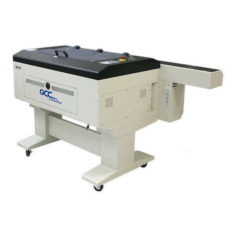
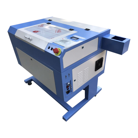
GCC Technologies LaserPro E200 Series User manual

4F., No.236, Fude 2nd Rd., Xizhi Dist., New Taipei City 22151, Taiwan 886-2-6616-6692 Fax:886-2-2694-6875
Version: 3.0
Release Jul., 2020
GCC LaserPro E200
User Manual

E200 User Manual I
Release Note
Version
Release Date
Change
1.0
Apr., 2020
First version
2.0
Jul., 2020
Second version
3.0
Sep., 2020
Third Version
3.0-1
Nov., 2020
Remove Chapter 5.2-7

E200 User Manual I
TABLE OF CONTENTS
Chapter 1 Safety..............................................................................................................................................5
1.1 Principles of a CO2 Laser................................................................................................................6
1.2 Safety Ratings....................................................................................................................................6
1.3 The Safety Interlock System............................................................................................................6
1.4 Safety Labels......................................................................................................................................6
1.5 Safety Measures..............................................................................................................................10
1.6 Operating Environment...................................................................................................................11
1.7 Noise Test .........................................................................................................................................11
Chapter 2 Unpacking....................................................................................................................................12
2.1Unloading and Unpacking...............................................................................................................13
Chapter 3 Mechanical Overview.................................................................................................................16
3.1 Front View.........................................................................................................................................17
3.2 Top View............................................................................................................................................17
3.3
Right
(Profile)
V
iew
.......................................................................................................................18
3.4
Left
(Profile)
V
iew
..........................................................................................................................18
3.5 Rear View
........................................................................................................................................19
3.6 Water Chiller Front View
.............................................................................................................20
3.7 Water Chiller Right View
.............................................................................................................21
3.8 Water Chiller Left View
................................................................................................................21
3.9 Water Chiller Rear View
..............................................................................................................21
Chapter 4 Machine Setup ............................................................................................................................22
4.1Water Chiller Setup..........................................................................................................................23
4.2E200 Machine Setup .......................................................................................................................26
Chapter 5 Software Setup ...........................................................................................................................28
5.1Recommended Computer Configuration......................................................................................29
5.2E200 Software - SmartJOB Installation ........................................................................................29
5.3E200 Driver Installation ...................................................................................................................32
Chapter 6 Connection Setup ........................................................................................................................33
6.1 Machine Connection Setup...........................................................................................................34
6.2Computer Assigns the Connection Method .................................................................................36
6.3 Connection Troubleshooting..........................................................................................................43
Chapter 7 Operating the GCC LaserPro E200.........................................................................................45
7.1 How to use focus tool......................................................................................................................46
E200 User Manual I
7.2 SmartJOB Software Operation.....................................................................................................48
7.2.1 User interface introduction..................................................................................................48
7.2.2 Functional Introduction........................................................................................................48
7.2.3 Trace Image Files ................................................................................................................49
7.2.4 Engraving & Cut by SmartJOB (workflow).......................................................................52
7.3 The LaserPro E200 Print Driver ....................................................................................................56
7.3.1 Page Setup and Orientation...............................................................................................56
7.3.2 Color Management...............................................................................................................58
7.3.3 Using the LaserPro E200 Print Driver...............................................................................59
7.3.4 Using the LaserPro E200 Print Driver >> Pen Page......................................................60
7.4 E200 Touch Panel Operation........................................................................................................69
7.4.1 Navigation Chart of E200 Touch Panel............................................................................69
7.4.2 Main Work Page...................................................................................................................70
7.4.3 Function Page.......................................................................................................................71
7.4.4 File Management Page.......................................................................................................72
7.4.5 File Management Page >> File Edit Raster Page ..........................................................72
7.4.6 File Management Page >> File Edit Vector Page...........................................................73
7.4.7 Machine Setting....................................................................................................................74
7.4.8 Other Page >> Air Delay Setting Page.............................................................................74
7.4.9 Offset Tuning ........................................................................................................................75
7.4.10 LED Light Setting...............................................................................................................76
7.4.11 Reset Page .........................................................................................................................76
7.4.12 Machine Information Page................................................................................................77
7.4.13 Advanced Option................................................................................................................78
7.4.14 Advanced Option >> Laser Status..................................................................................78
7.4.15 Advanced Option >> Origin Position...............................................................................79
Chapter 8.........................................................................................................................................................80
Optional Items...............................................................................................................................................80
8.1 Fume Extraction System Option ...................................................................................................81
8.1.1 INST
ALLA
TION
(Self-Assembled
Unit)
.........................................................................81
8.2 Air Compressor Option ...................................................................................................................82
8.3 Rotary Attachment Option.............................................................................................................85
Chapter 9.........................................................................................................................................................91
Basic Maintenance.......................................................................................................................................91
9.1 Suggested Cleaning and Maintenance Supplies........................................................................92

E200 User Manual I
9.2 Maintaining the Worktable and Motion System..........................................................................93
9.2.1 Cleaning the Worktable and Motion System....................................................................93
9.2.2 Lubrication of the X / Y Rails..............................................................................................94
9.3 Cleaning the Optics System ..........................................................................................................95
9.3.1 Cleaning the Mirrors ............................................................................................................95
9.3.3 Removing and Cleaning the Focal Lens ..........................................................................96
Chapter 10 Appendix ....................................................................................................................................98
10.1 GCC LaserPro E200 Specification sheet.................................................................................99

5
Chapter 1
Safety
Principles of CO2 Laser
Safety Ratings
The Safety Interlock System
Safety Labels
Safety Measures
Operating Environment

6
1.1 Principles of a CO2 Laser
LASER is the acronym for Light Amplification by Stimulated Emission of Radiation. A CO2 laser works by
electrically stimulating the molecules within a carbon dioxide gas mixture. When focused through a lens,
this highly-intense, invisible beam will vaporize many materials. Depending on the speed and intensity of the
projected beam, a CO2 laser may be used to engrave or cut through a wide variety of materials.
1.2 Safety Ratings
The LaserPro E200 is equipped with a sealed carbon-dioxide laser that emits intense and invisible laser
radiation with a wavelength of 10.6 microns in the infrared spectrum. Althoughthelasertube itself is
classified as a Class IV laser product. The laser system is designated as a Class I laser device, meaning that
the system is equipped with key safety features and an enclosed laser head to completely contain the laser
under normal use. One of the key safety features found on the LaserPro E200 is a Class 2 red beam safety
guidance pointer (similar to a laser-pointer presentation pen) allowing the operator to see the exact location
where the laser beam will fire. Even though the LaserPro E200 is equipped with our most powerful laser to
date, proper usage and hardware safeguards make it an extremely safe machine. When the front door and
back door are open, machine becomes Class 4 equipment and users must wear goggles to operate the
machine.
1.3 The Safety Interlock System
The laser system is equipped with a safety interlock system utilizing magnetic sensors on the top and
side access doors, laser-activation and door LED lights on the control panel. The magnetic sensors will
deactivate the laser when either door is opened. At this time, the "door" LED light found on the control panel
will illuminate, indicating an open or improperly closed door. When the laser is in operation, the "laser" LED
will illuminate to inform the operator that the laser is activated. If at any time, any of the access doors are
open and the "laser" LED is illuminated, IMMEDIATELY unplugs the laser system and contact GCC technical
support for service instructions.
WARNING
・DO NOT operate the laser system if any component of the safety system is malfunctioning.
・DO NOT attempt to remove or modify any component of the safety interlock system.
1.4 Safety Labels
According to CDRH standards, all fixed or removable covers that allow access to a laser beam must have
the appropriate laser warning labels attached to them. These warning labels must be clearly visible to the
operator prior to removing the cover. Additional labels must be applied inside of the machine and be visible in
the event the covers are removed. A label clearly displaying the manufacturer’s name, date of manufacture,
description of product, model number, serial number, and compliance statement must be attached to the
outside of the machine.

7
In compliance with CDRH standards, the required warning labels are affixed at the time of manufacture to the
LaserPro E200 in the appropriate locations. These labels are not to be modified in any way or removed for
any reason. Please familiarize yourself with the specific labels and their locations on the machine. Below is a
list of all the safety labels and their locations on the machine.
Product Label
This label is located at the right-back side of machine. All the product information such as Serial Number,
Model Numbers, Laser Power and Electric power can be found here. Before requiring any tech support,
always provide service person the information on this label.
Safety
Label
CDRH and CE regulations require that all laser manufacturers add warning labels in specific locations throughout
the equipment. The following warning labels are placed on the laser system for your safety. Do not remove these
labels for any reason. If the labels become damaged or have been removed for any reason, do not operate the
laser system and immediately contact Great Computer Cooperation or e-mail us for a replacement.
Door open warning labels

8
CDRH Label
This label indicates the class level of CDRH.
CE
Label
This label identifies the classification of the Model in accordance with IEC 60825-1. It is located on the rear of the
machine’s cabinet.
Aperture warning stickers (mirror):
This label indicates the laser path. Normally you can find this label inside of machine or laser exit. Please
take extra caution of this area when you conduct maintenance or operate machine.
Aperture warning stickers
DANGEROUS VOLTAGES ARE PRESENT WITHIN THE ELECTRONICS ENCLOSURES OF THIS SYSTEM.
Access to these areas is not necessary during normal operation. If it becomes necessary to open one of these
enclosures for service reasons, please remember to disconnect the power cord from your electrical supply.

9
Warning Label
Warning Label is written with all the necessary information to be aware of during operation.
Invisible laser radiation when door open and interlock failed.
Avoid eye or skin exposure direct to laser radiation.
Do not leave the machine unattended during operation.
Please clean the bearings and motion system tracks every day.
Do not use reflective metals, heat sensitive surface or materials that may produce toxic substances or corrosion
problems, such as PVC and Teflon.
Laser Path Warning Label
LaserPro machines are very safe under normal use. Furthermore, Laser Path Warning Labels are displayedat the
proximities of possible laser paths as a reminder. Operators should exercise caution when working close to
these laser paths to avoid possible injury while machine is turned on.
Laser Path Danger label
This label indicates the laser path. Normally you can find this label inside of machine. Please be very careful
of this area when you do the maintenance.

10
NOTE
Each LaserPro laser machine is shipped with a single pair of safety goggles. If additional
safety goggles are required, please contact GCC directly or an authorized GCC
distributor. If you wish to purchase one on your own, please make sure the safety
goggles meet these requirements:
9000-11000nm OD5+
Visible Light Transmission: 92.9%
1.5 Safety Measures
• LASER RADIATION WARNING: Exposure to laser radiation may result in physical burns and
severe eye damage. Proper use and regular maintenance of this machine is important to the
safety of all people in the immediate area.
•Prior to operation, carefully read and familiarize yourself with the warning labels located on
both your laser system and in this manual.
•Never leave the machine unattended during the laser cutting and engraving process. The laser
may ignite combustible materials. A well-maintained fire extinguisher and operational smoke or
fire detector should be kept in the vicinity of the machine.
•Caution—Use of controls or adjustments or performance of procedures other than those
specified herein may result in hazardous radiation exposure.
•GCC cannot be held responsible for any direct or indirect damages, which result from using or
working with the products electric circuits or software described herein. The apparatus must be
used only by trained and skilled personnel. Before using the machine, user should read and
follow the manuals carefully. Furthermore GCC reserves the right to change or alter any product
described herein without prior notice.
•Resulting debris from laser cutting are very dangerous and may cause fire hazard.
DO NOT leave debris and scraps inside laser machine after job finished. Must keep
machine clean after job finished.
W
A
RNING
・Resulting debris from laser processing are very dangerous and may cause fire hazard
・DO NOT leave debris and scraps inside laser machine after job finished. Must keep
machine clean after job finished.
・Always remove the vector grid or honeycomb table to clean any small pieces that have
fallen through the grid.
•Connect the machine to a properly grounded power outlet. Ensure the voltage of the power
source is identical to the voltage of the machine.
•Do not open the laser access panel when the machine is plugged in.
•Do not attempt to modify or disassemble the laser module.
•Do not attempt to remove or modify any component of the machine’s laser interlock safety
system.
•Ensure the immediate work area of the machine is well-ventilated. Odors, vapors, and dust are by
products generated during the laser engraving and cutting process. An exhaust system, vacuum
cutting box, and honeycomb table are recommended. Please contact GCC or your local GCC
distributor for more information.
• Do not laser heat-sensitive surfaces or materials that may generate toxic fumes, such as PVC and
Teflon
Regularly clean and maintain your machine according to our cleaning and maintenance
instructions. Doing so will ensure a machine that will operate effectively and safely over a long
period of time.

11
1.6 Operating Environment
Please follow the guidelines when considering a suitable location to set the LaserPro E200. Improper work
environments may lead to operational malfunction and/or unsafe working conditions. The LaserPro E200
should be placed and operated in a standard office-type environment.
•Avoid environments where the machine is exposed to high levels of dust, temperature
(temperatures exceeding 30°C or 85°F) or humidity (humidity exceeding 70% or where the
ambient temperature is near the dew point).
•Avoid small, enclosed areas with poor ventilation.
•Avoid areas with high levels of noise and electrical noise.
•Select a location that is large enough to accommodate the LaserPro E200, an exhaust system,
a computer and a work or storage table.
•Select a location in which the ambient temperature remains between 15°C and 30°C (60°F to
85°F).
•Select a location in which the relative humidity remains between 30% - 40%.
•Select a location in which there is a short, direct path to the fume exhaust system.
•Set the LaserPro E200 on a floor surface that is completely even.
•Make sure your smoke or fire detection system in the immediate area is functioning.
•Setup the machine to be at least 60 cm (2 feet) away from the wall.
1.7 Noise Test
Test Conditions: measured at a distance of 1 meter from the surface of the machinery and a height of 1.6
meters from the floor or access platform.
E200 40W Sound Test Result: 68.4 dB

12
Chapter 2
Unpacking
Unloading & Unpacking

13
WARNING
More than one person may be needed when loading and unloading the shipping crate
in order to avoid body injury or damage to the machine.
2.1 Unloading and Unpacking
The GCC LaserPro E200 is shipped in one crate that contains machine, software, and all of the necessary
accessories. The following section shows detailed step-by-step instructions for unpacking and assembly the
accessory to workstation.
1) Move the shipping crate to the proximity of the designated work area.
2) Remove the top cover carton.
NOTE
Please keep and store the original shipping crate in case it is needed for future transportation or
product servicing.

14
3) Remove the packing foam on the top.
4) Remove the side-cover carton.
5) Release the four safety blocks that hold the machine in place.

15
6) Take out the water chiller and the accessory box.
7) Now you can take out the machine.
8) Lastly take out the laser materials which we enclose within E200.

16
Chapter 3
Mechanical Overview
Front View
Right View
Left View
Rear View
Water Chiller Front View
Water Chiller Right View
Water Chiller Left View
Water Chiller Rear View

17
Please take some time to familiarize yourself with this section regarding the mechanical overview of the LaserPro
E200. References will be made back to the different parts of the LaserPro E200 in later sections.
3.1 Front View
3.2 Top View

18
3.3
Right
(Profile)
V
iew
3.4
Left
(Profile)
V
iew

19
3.5 Rear View
This manual suits for next models
1
Table of contents
Other GCC Technologies Engraver manuals

GCC Technologies
GCC Technologies LaserPro Spirit Series User manual

GCC Technologies
GCC Technologies LaserPro Venus II User manual

GCC Technologies
GCC Technologies S290LS Series User manual

GCC Technologies
GCC Technologies LaserPro C180 User manual

GCC Technologies
GCC Technologies StellarMark 3DS User manual

GCC Technologies
GCC Technologies LaserPro C180II User manual

GCC Technologies
GCC Technologies LaserPro SmartCut X380 Series User manual

GCC Technologies
GCC Technologies LaserPro X252 User manual

GCC Technologies
GCC Technologies LaserPro S400 User manual

GCC Technologies
GCC Technologies LaserPro DFS User manual